Is Input Shaper not working or what's causing ringing?
-
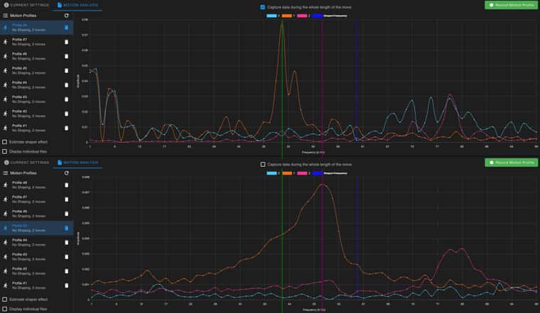
@dc42 check this out, I've recorded 14 IS graphs with no shaper configured to get a baseline and see how consistent readings I can get.
Notice the difference on the last 4 images, only thing I did was to restart the 6HC. Printer is in another room, nothing was printed and no one touched it. It's like 1min between those graphs.
I can not wrap my head around how to set this up.
-
@Reine I wonder why your graphs are so unstable, I am really worried you aren't measuring the right frequencies or your printer has some build issues we haven't figured out yet.
-
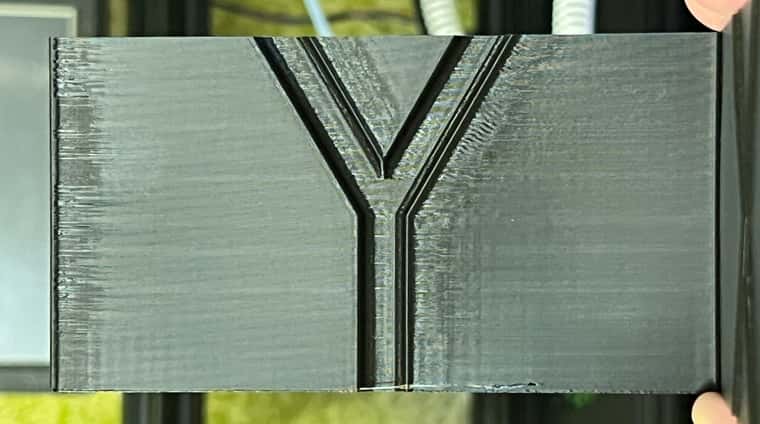
The testing continues. Today I've been using the Voron ringing tower.
In this example I've added a script that changes IS every 5mm in PrusaSlicer. It starts off with none, then goes to zvd 20 and increments by 5 until it reaches 70. Dampening 0.1.
Mesh is off and Pressure Advance is also off.
I've confirmed all settings while printing, even that IS is changing (with M593) and it's all correct.It's printed in vase mode, 225mm/sec & 4k accl, Jerk 2 as those were the best settings I found yesterday.
But as you can see in the video, there's no difference (what I can tell) between no IS, zvd@20 and zvd@70.
Something else must be interfering so it's not even working?
I've even printed one tower with all shapers at the same hz and couldn't tell much of a difference if any at all.
RRF 3.4.6.
https://imgur.com/a/tC5WESD@dc42 any ideas?
-
@Reine What steppers are you using? What amperage are they rated for? And what motor current are they set for in your M906 command? We've seen artifacts that, at first glance, appeared to be ringing only to discover it was due to underpowering the steppers..
-
@oozeBot LDO-42STH48-2504AC I've tested between 1.6 - 2A, think they are rated to 2.5.
-
-
When we switched to a variant of the 2504 steppers, one of our machines was showing signs of ringing not present on others, which led us on a bit of good chase. It was never as pronounced as Op’s example though (photo below). What it turned out to be was the config on that machine still had the values for the 2004 steppers at 1750 mA.
We run the class H (High Temp) model of the 2504 steppers and set them to 2250 mA while in operation. That’s high, but they can take it without issue and our 6HC main boards are actively cooled.
 image url))
 -
This post is deleted! -
@oozeBot I've upped my steppers to 2A, can't see much difference in temp on the 6HC but the steppers are slowly going up, not sure how high though as I haven't printed anything big yet.
What's a safe temp reading on their outer casing?
-
These two graphs are taken just minutes apart -- explain to me why they are so different and why the peak is not at the same frequency?
-
@Reine Just to be clear (in case others don't spot it), one set has the "capture data during entire move option" check on one but not on the other. This means you will be collecting data that includes motor vibration etc. on one but not on the other. I think the theory is that it is better to collect data after the move so that what you see is the resonance induced by the impulse but I'm no expert. The other thing to note is that the scales on the two graphs are very different (an order of magnitude), so the "peaks" in the second graph will be down in the noise of the first. Personally I don't really like the mechanism used to collect resonance data by RRF (I think the Klipper approach of basically sweeping a set of vibrations over the range, produces a stronger set of readings).
But I'm not sure the different readings you show relate to the print artefacts you are seeing. Though perhaps the fact that you get a 10x higher peak with the motors active is significant?
Looking at your earlier posts it would seem from the graphs in your first post that IS is having some impact on the resonances being shown. But perhaps those are not the cause of the artefacts you are seeing? What seems a little odd to me in the photos is that the "ringing" seems to be very spaced out (which may indicate a very low frequency) compared to what I've seen in other cases. Did you ever try estimating the frequency manually? See: https://www.klipper3d.org/Resonance_Compensation.html for a way to do this.
-
@gloomyandy I haven't used Klipper but that approach seams better to me too, an option to do X scans and average out the result and remove outliers would be a step in the right direction for the IS plugin imo.
Good point, the magnitude axis should haven an option to be fixed so it's easier to compare.
I did do the math now and came up with about 45Hz, it's lower than the graphs but not by much so that seams about right.
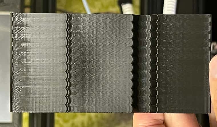
The ei3 print just finished and here is a comparsion with the zvd print I did earlier. Finally a difference, sadly still no change in the Hz range it's testing.
;AFTER_LAYER_CHANGE
{if layer_z >=  0}M593 P"ei3" F35 S0.1{endif}
{if layer_z >=  5}M593 P"ei3" F37 S0.1{endif}
{if layer_z >= 10}M593 P"ei3" F39 S0.1{endif}
{if layer_z >= 15}M593 P"ei3" F41 S0.1{endif}
{if layer_z >= 20}M593 P"ei3" F43 S0.1{endif}
{if layer_z >= 25}M593 P"ei3" F45 S0.1{endif}
{if layer_z >= 30}M593 P"ei3" F56 S0.1{endif}
{if layer_z >= 35}M593 P"ei3" F58 S0.1{endif}
{if layer_z >= 40}M593 P"ei3" F60 S0.1{endif}
{if layer_z >= 45}M593 P"ei3" F62 S0.1{endif}
{if layer_z >= 50}M593 P"ei3" F64 S0.1{endif}
{if layer_z >= 55}M593 P"ei3" F66 S0.1{endif}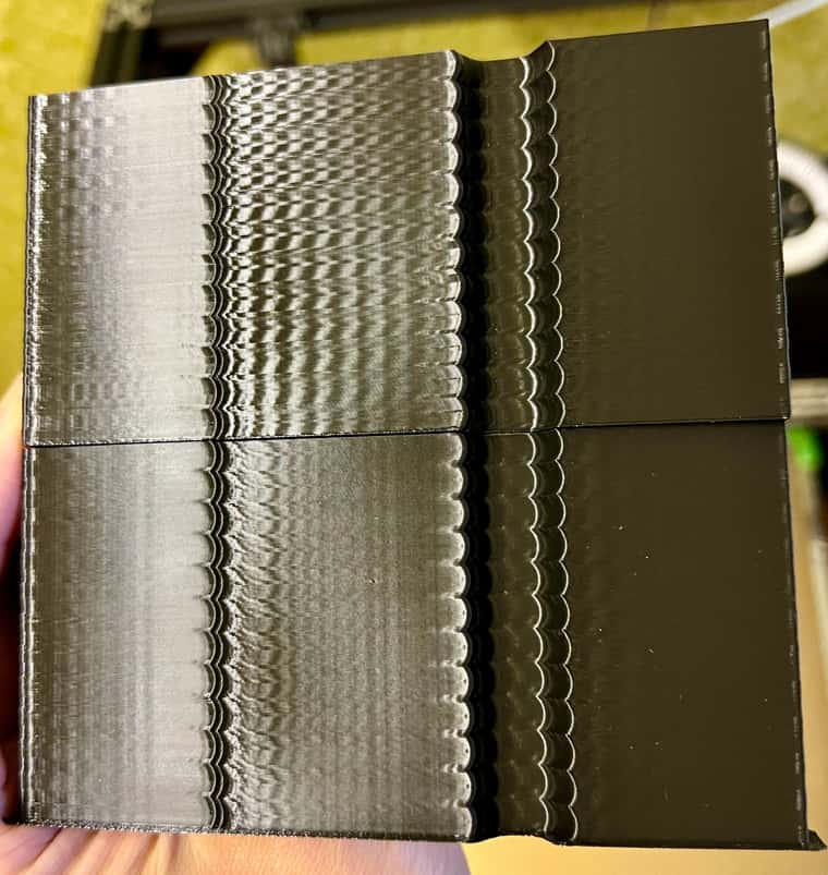
(zvd bottom, ei3 on top)Here's the gcode for that print, is there some issue in it preventing IS to update after each 5mm segment?
acceleration_test_piece_0.2mm_PLA_24m.gcode -
@Reine Is that caption correct it shows ei2 not ei3 also is it zvd on top or bottom? I'd have expected the ei3 (assuming it is that) to probably have more impact than zvd.
It would be useful to see a full print of that ringing test with all of the same settings but with IS turned off. So we can get an idea if IS is having any impact or not.
-
@gloomyandy you're correct, it was a typo. EI3 ontop and ZVD bottom.
Let me do another print with all different shapers at the same Hz. What Hz do you recommend I use?
-
@Reine I'm confused that zvd (bottom) print looks to me much better than the ei3 (top)version. Which I'm surprised at. Which looks best to you? As I said a print with no IS would be the best so we can see what the original problem was.
-
As I'm constantly getting a spike in Z and nothing in X I suspect the orientation guide might be wrong, I've been using I10 but now switched to I16 which looks more correct.
M955 P121.0 I16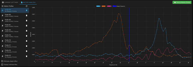
-
@Reine You should be able to check the orientation (at least for Z) by checking the results from a data collection with no movement using M956 (https://docs.duet3d.com/en/User_manual/Reference/Gcodes#m956-collect-accelerometer-data-and-write-to-file) if you look at the file two of the readings (x and Y) should be close to zero and the 3rd Z should be around 1G.
-
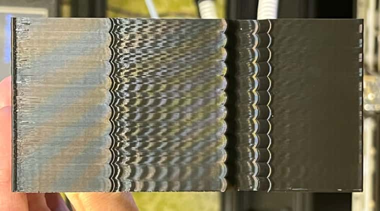
@gloomyandy here we go, same everything except for the shaping is done like this now.
;[layer_z]
{if layer_z >=  0}M593 P"none"{endif}
{if layer_z >=  5}M593 P"none"{endif}
{if layer_z >= 10}M593 P"mzv" F80 S0.1{endif}
{if layer_z >= 15}M593 P"mzv" F67 S0.1{endif}
{if layer_z >= 20}M593 P"zvd" F80 S0.1{endif}
{if layer_z >= 25}M593 P"zvd" F67 S0.1{endif}
{if layer_z >= 30}M593 P"zvdd" F80 S0.1{endif}
{if layer_z >= 35}M593 P"zvdd" F67 S0.1{endif}
{if layer_z >= 40}M593 P"zvddd" F80 S0.1{endif}
{if layer_z >= 45}M593 P"zvddd" F67 S0.1{endif}
{if layer_z >= 50}M593 P"ei2" F80 S0.1{endif}
{if layer_z >= 55}M593 P"ei2" F67 S0.1{endif}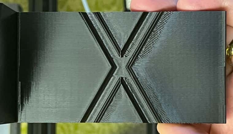
-
@Reine What happens if you target the frequency you previously calculated 45Hz? You might also want to try setting the damping factor to 0 (see DC42's comments here: https://forum.duet3d.com/topic/33243/which-input-shaping).
-
@gloomyandy
M956 P121.0 S20 A0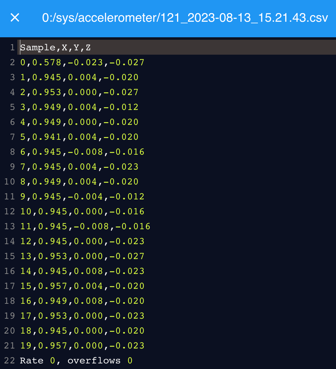
This does indeed look wrong.. I10 looks correct, but then I don't understand why the X axis is smooth and Z have a spike?