Gang Printing Mode
-
I have a fairly large 3D printer that I'm steadily adding more and more hotends and extruders to. It is currently dual-extrusion (two Orbiter v1.5 + Dragon hotends in direct drive), but I'm planning to upgrade to Quad extrusion in the near future (likely four BMGs in bowden mode, with two Volcano Chimeras).
Obviously, putting multiple materials into a single part is cool, and configuring that is pretty straight forward. What I need help with is using the printer to print two of the same part, at the same time, in parallel.
I'm working on a slicing profile for S3D that will halve my X-axis width, and a macro that will help me space the two extruders equally on the X-axis (for switching modes), but I'm not sure how to make the printer pre-heat and monitor both hotends and drive both extruders, when it's only receiving commands for a single tool.
Do I simply need to update my M563 in that macro to define Tool 0 to use both extruders, both heaters (which are mapped to both sensors), and both part cooling fans? Or is there more to it?
Thanks in advance.
-
@KnyteTech are your two hot ends driven independently in the X direction, IDEX style?
-
@KnyteTech If your machine is an IDEX (which it sounds like it is), see https://docs.duet3d.com/User_manual/Machine_configuration/Configuration_IDEX
If you have independent X and Y axes for each tool, it's much the same, you just need to map Y movement to both Y and V as well.Ian
-
TL;DR - the command I needed was "M567 P0 E1.00:1.00" combined with defining a single tool that contained all fans, heaters, and extruders. So I was able to get it working in time for the show I was going to.
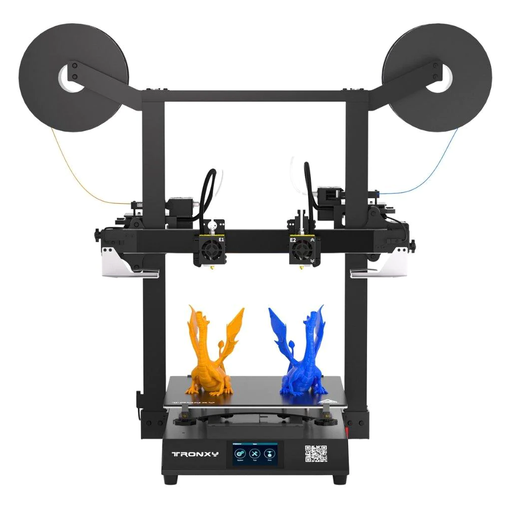
It's a standard I3 printer, and I wanted to be able to convert it between what I now know is called Clone Mode, and standard dual extrusion, because I plan to upgrade to dual Volcano Chimera hotends in the near-future, and it would be amazing to change between running two dual-extruder configurations in parallel, and a single quad-extruder setup with minimal effort - this is step one on that journey. I needed to get it running, so I could figure out what I needed to add to my hot-end carriage design to facilitate calibration, and changing between the two modes reliably.
So here's what I've done so far (Simplify 3D is my slicer, in case that matters):
-
Updated the slicer profile to have Extruder 1 and Extruder 2, a second heater on the hot end, and second part cooling fan. No changes to the starting or ending scripts, just halved the X-axis build volume. It is otherwise identical to my standard slicing profile for the printer.
-
I updated config.g to add the new heater, fans, and the two hot ends as separate tools (my hot end fans are always on, so they're not in the tool definition below):
; Tools M563 P0 D0 H1 F0 ; define tool 0 G10 P0 X0 Y0 Z0 ; set tool 0 axis offsets G10 P0 R0 S0 ; set initial tool 0 active and standby temperatures to 0C M563 P1 D1 H2 F1 ; define tool 1 G10 P1 X87 Y0 Z0 ; set tool 1 axis offsets G10 P1 R0 S0 ; set initial tool 1 active and standby temperatures to 0C- Then I created a Macro to restore the default state of a standard dual-extruder configuration:
; Build Volume Reset M208 X-87 Y-0 Z0 S1 ; set axis minima M208 X260 Y350 Z495 S0 ; set axis maxima ; Tools M563 P0 D0 H1 F0 ; define tool 0 G10 P0 X0 Y0 Z0 ; set tool 0 axis offsets G10 P0 R0 S0 ; set initial tool 0 active and standby temperatures to 0C M563 P1 D1 H2 F1 ; define tool 1 G10 P1 X87 Y0 Z0 ; set tool 1 axis offsets G10 P1 R0 S0 ; set initial tool 1 active and standby temperatures to 0C- Finally, I created a macro to enable Clone printing mode. Initially, it helps you to put Extruder 2 almost-exactly 175mm away from Extruder 1, with minimal effort (just unclamping from the belt, the printer moves Extruder 1 away while you hold Extruder 2 in place, then prompts you to re-clamp the belt), then it updates all the printer settings to reflect a single massive tool.
;Head Moving Script
G28 X ;Home X-axis
G1 X{175-tools[1].offsets[0]} F3600 ;Move Tool 2 to X-Axis center
M400
M291 S3 P"Unclamp Extruder 2 from the belt and hold it still. Press OK to continue."
G1 X0 F1200 ;Set Head Spacing
M400
M291 S3 P"Re-tightend clamp to the belt. Press OK to complete."

;Update Tool Command to create one massive tool
M563 P1 D-1 H-1                                    ; Delete Tool 1
M563 P0:1 D0:1 H1:2 F0:1                    ; define tool 0
G10 P0 X0 Y0 Z0                                     ; set tool 0 axis offsets
G10 P0 R0 S0                                          ; set initial tool 0 active and standby temperatures to 0C
M567 P0 E1.00:1.00                               ;Set tool 0 to drive both extruders

; Axis Limits (Single, Dual Ducts)
M18
M400
M208 X-43:175 Y0:350 Z0:495       ; set axis min and max

G28 X ;Home X again
G1 X0 F3600 ;Move to X=0
M291 S1 P"Confirm Extruder 2 is now in the middle of the bed."
T0
The command I was looking for was a way to tell the printer to drive BOTH extruders on the tool, when only one extruder was being commanded to move, and M567 was what was needed.
I also learned during testing that the M18 was needed in that last macro so the printer would accept the new Axis Minimum value. When I didn't have the M18 in there, the final G28 X was still homing to X-87 which would then drive the whole thing to out of position, but by turning off the motors before I redefined the build volume, it would then report the updated X-minimum value reliably.
-
-
@KnyteTech said in Gang Printing Mode:
TL;DR - the command I needed was "M567 P0 E1.00:1.00" combined with defining a single tool that contained all fans, heaters, and extruders. So I was able to get it working in time for the show I was going to.
Just want to verify - by a standard I3 printer (with what I believe you're describing as independent dual extruders) - is this what you're describing?

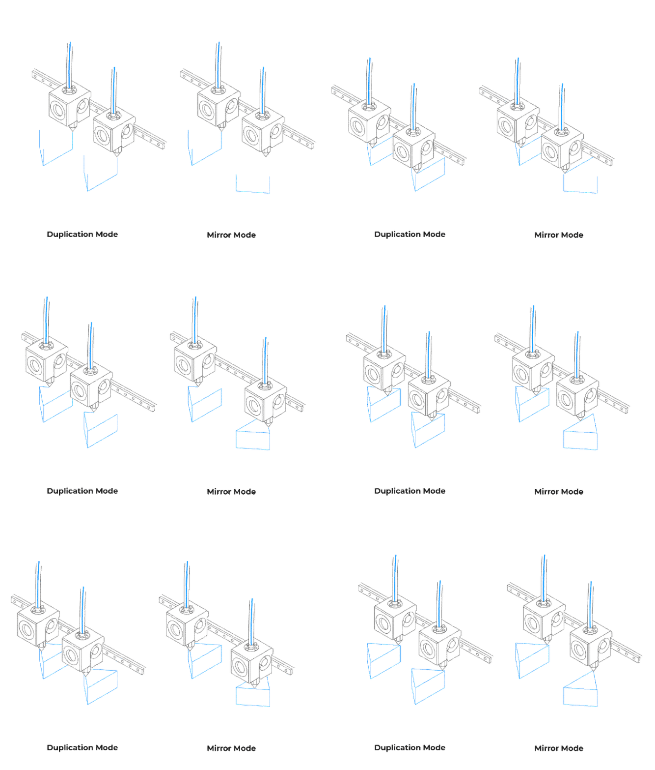
And by gang printing (like you say, clone mode) you mean what is occurring below as duplication mode:

If you have (and are trying to do) the above, I think you can simplify your configurations by using the built in RRF functionality for IDEX printers.
Configure your T0 tool (oftentimes the 'left' extruder/tool) and your T1 tool (oftentimes the 'right' extruder/tool) as normal, with T1 being typically mapped to the 'U' axis, and T0 being mapped to the 'X' axis. Example from my printer:
M563 P0 D0 H1 F5                               ; Define tool 0, extruder 0, heater 1, fan 5
G10 P0 X0 Y0 Z0                             ; Set tool 0 axis offsets
G10 P0 R0 S0                                ; Set initial tool 0 active and standby temperatures to 0C

M563 P1 D1 H2 X3                            ; Define tool 1, extruder 1, heater 2, maps X to U
G10 P1 X0 Y.0 U0 Z.2							; Set tool 1 axis offsets
G10 P1 R0 S0                                ; Set initial tool 1 active and standby temperatures to 0C
Using T0 and T1 as shown above lets me do a dual material print (build material and support, multi-color, different nozzle sizes, etc)
I then have defined a T2 (so tool #3) for printing 'clone' (or duplication mode, as seen above). My printer is configured such that the center of the build plate is X=0, Y=0, so using the following lets me set the offset between the two tools (basically what it seems like you're manually doing with unclamping/clamping the belts?):
M563 P2 D0:1 H1:2 X0:3 F5						; tool 2 uses both extruders and hot end heaters, maps X to both X and U, both fans
G10 P2 X0 Y0 U-263.5 S0 R0    				; set tool offsets and temperatures for tool 2
M567 P2 E1:1 ; set mix ratio 100% on both extruders
(I forget if the M567 command is even necessary, haven't been working much with the 3D printer lately aside from some single extrusion jigs).
Some prefer to apply the offset equally between the two hotends/extruders, like so - pick your poison (I prefer the above M563)
G10 P2 X131.75 Y0 U-131.75 S0 R0 ; set tool offsets and temperatures for tool 2
Now, this all goes out the window if you don't have what is considered an IDEX printer (not having a second motor for the X axis to control that second tool/hotend/extruder). I'm looking at your M563s somewhat in a vacuum, and a little confused on if you actually have an IDEX setup based on that.
If you share a picture or two of your printer, plus the full config.g, we may be able to help more. My guts says you're trying to solve a solution with macros/configurations that can be natively resolved with a T2 configuration, but I could be wrong.
-
@sebkritikel when I said "a standard i3 printer" I meant a regular i3 printer shape (a la Ender 3, Prusa Mk4, etc), and not and IDEX printer.
I was trying to add the functionality of an IDEX's duplication/clone mode to a non-IDEX printer. I built the printer with two X-axis carriages on two linear bearing blocks, on a shared MGN15 rail, driven by a single X-axis motor. Each carriage has a clamp on the top that grabs onto the belt, so they are easy to reposition quickly.
The idea behind the macros is that right now, returning to "regular" dual extrusion is going to be inaccurate since my existing carriages weren't really intended for this, so they can't index off of each other accurately, but this is a function that I specifically want to include in the "final" version of my printer - I already knew I needed to re-design my X-axis carriages to make them more modular, but this definitely added some ideas for features that needed to be included to make this kind of function-change easier.
The Macros make it easier to reposition the heads on the belt that drives both carriages, and once the carriages are re-designed to include the added features I thought of, it'll be both more-automatic and more precise, but still require a little manual intervention.
The printer running: https://www.instagram.com/p/CxvR9s2gZuV/ (it's a 350x350x500mm build volume, Orbiter V1.5 extruders and Dragon HF hot ends, with a BL touch). I'm planning to replace the BL touch with a simple micro switch, add a DUEX board, and move to a part of Volcano Chimeras running in bowden mode, possibly still using Orbiter's, but more likely a BMG clone.
Thanks for the info on defining a third tool - I will be playing around with that and see how I like it compared to the way it's running now.
-
This post is deleted!