Duet3 Mini5+ Ethernet Nozzle Distance to PEI sheet is too large
-
@droftarts Wow thanks
I was amazed myself!
This was really very easy with just one click of the mouse.
The Duet Mini, the 1LC and the DWC are now displayed in a list in the interface for the first time and all have the same version: 3.5.0-rc.1; Thank you. Horror fairy tales were then told on the Internet.
Now I'll test it first and then finally connect the LEDs.
I'll get back. -
@Wobi well done! Updating to regular release firmware is generally even easier, as there is a zip file with all the firmware components, and you just upload that.
Ian
Bed-slinger - Mini5+ WiFi/1LC | RRP Fisher v1 - D2 WiFi | Polargraph - D2 WiFi | TronXY X5S - 6HC/Roto | CNC router - 6HC | Tractus3D T1250 - D2 Eth
-
@droftarts
Hello Jan, the tests were a bit extensive and initially not successful and have not yet been completed but now the printing is finally working, not yet perfect but usable, I have attached a photo testdruck.jpg of the first successful test print with PETG, again thank you for your competent help.
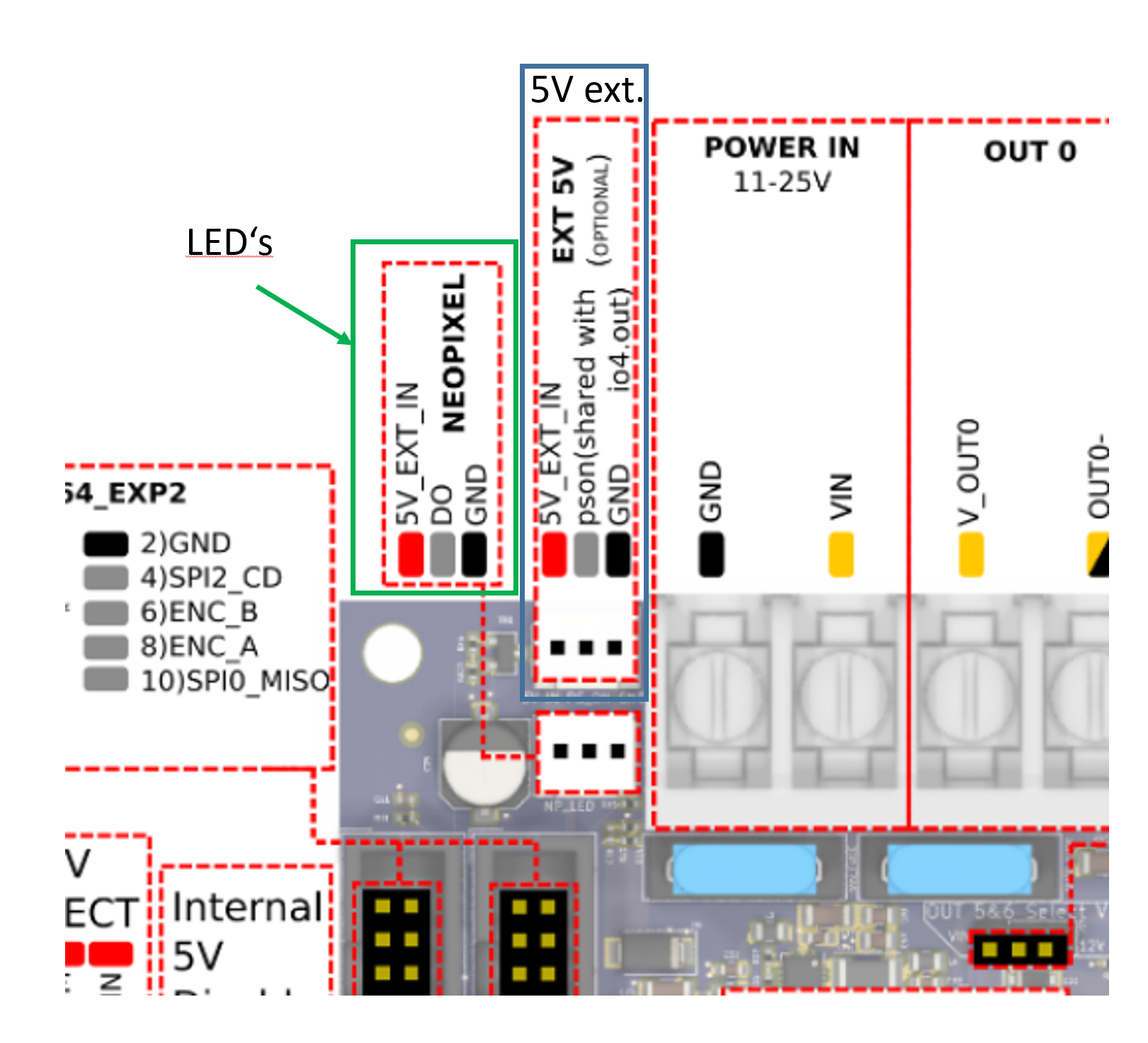
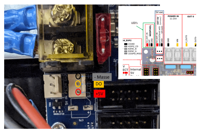
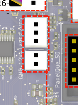
Unfortunately the LEDs still don't work. I also don't know which PIN name I have to use in the command. 'NEOPIXEL' or 'DO' or something completely different, see photo leds.png? I connected the external 5 volt 5 amp voltage source right next to it, I hope that's correct or do I still have to set/remove a jumper?
In 'config.g' I added these lines at the very end:
M950 E0 C"led" T1 Q3000000
M150 E0 U255 B255 P255 S1 F1
M501 ;was already there
Can you please tell me the correct command lines?
And another question about the DWC interface, in the previous version I could call up and view the mesh grid, this option is now completely missing, how can I display the mesh now?
Thanks for your help
Wobi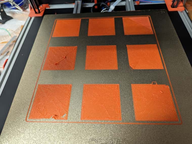
-
@Wobi I had a look at this guide: https://docs.vorondesign.com/community/howto/drachenkatze/neopixel_guide.html
And also I looked at https://www.dhm-online.com/en/voron-2-4/10529-kit-voron-24-300-mm-pitch-step-7-stealthburner-hot-end-revo-voron.html that seems to supply this set of LEDs https://www.dhm-online.com/en/led/12720-neopixel-rgbw-led-kit-wired-for-stealthburner-printer-voron.html which is perhaps like the Stealthburner kit you got? If it's only 3 LEDs, you should be able okay supply 5V via the board, as these LEDs can draw up to 80mA (peak) per LED, and usually about half of that if you're using colour. But first, check:- check you get 5V between 5V_EXT_IN and GND, on the EXT 5V connector, and then on the NEOPIXEL header.
- check whether you have RGB or RGBW LEDs (the kit says RGBW):
RGBW LEDs will have a visible yellow-ish phosphor section to the chip. If your LEDs do not havethis yellow portion, you have RGB LEDs.
- The Voron guide says "The data is sent with a signal rate of 800kHz", so 3MHz may be too fast. This datasheet from Adafruit also says 800KHz.
- the pin name for the Neopixel D0 pin is 'led'.
With the above information, I think a better M950 command may be:
M950 E0 C"led" T2 Q800000Send that and then test with your M150 command.
Note the use of the M150 S and F parameters:Snnn Number of individual LEDs to set to these colours, default 1
Fn Following command action. F0 (default) means this is the last command for the LED strip, so the next M150 command starts at the beginning of the strip. F1 means further M150 commands for the remainder of the strip follow this one.So
M150 E0 ... S1 F1will set the first LED, then wait for another command. You need to send an M150 command that ends with F0 to set the LEDs. Try:M150 E0 U255 B255 P255 S3 F0This should set the first three LEDs to full brightness on green and blue.
Hopefully that gets you going. Once it is working on the mainboard, are you going to try them on the toolboard? I think there is only one pin you can use for the LEDs, and that is io0.out. This is a 3.3V pin, but it may still work with a short LED strip without level shifting the 3.3V to 5V.
Let me know if that works.
Ian
Bed-slinger - Mini5+ WiFi/1LC | RRP Fisher v1 - D2 WiFi | Polargraph - D2 WiFi | TronXY X5S - 6HC/Roto | CNC router - 6HC | Tractus3D T1250 - D2 Eth
-
@droftarts
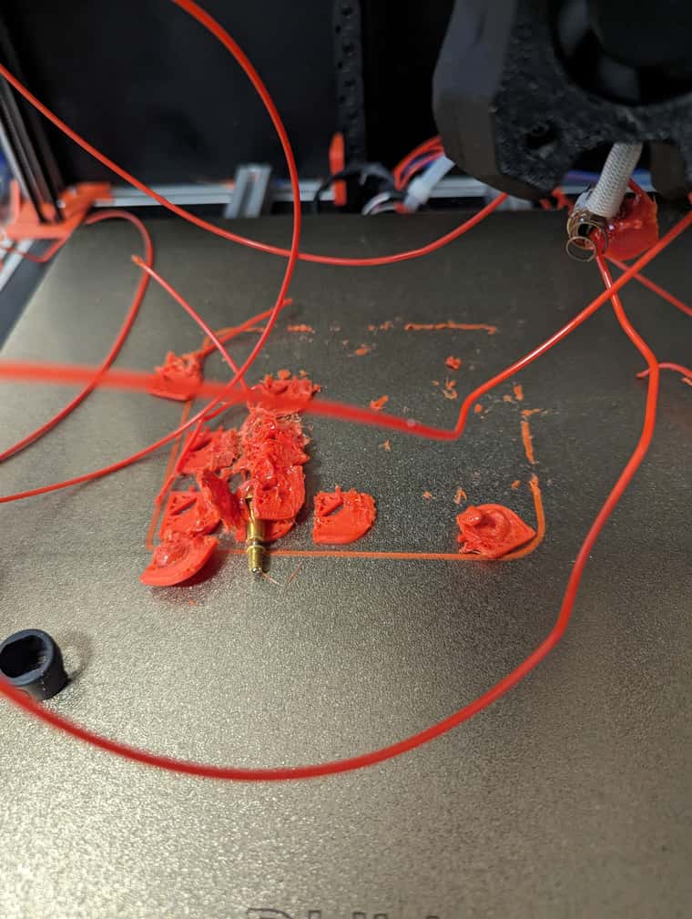
Hello Ian, thanks for the links, I tried the new commands straight away, unfortunately no success, so I have to measure the cables again and connect another LED. Then, today at noon there was a crash. The V6 nozzle broke off during an unattended print job. Since I wasn't there, I have no idea what exactly happened.
Now I have to order and install a new Revo V6 hotend, which may take a while. In the meantime I have listed the defective Voron on eBay, let's see what happens.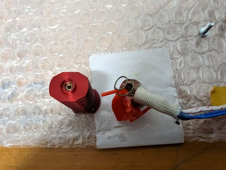
-
@Wobi Oh dear, that's not good! I can't imagine what would have caused that, unless the nozzle unscrewed itself and dropped out. Does this mean you're getting rid of the whole printer?
I'm going to order myself some SK6812 RGBW LEDs to test various ways of connecting them.
Ian
Bed-slinger - Mini5+ WiFi/1LC | RRP Fisher v1 - D2 WiFi | Polargraph - D2 WiFi | TronXY X5S - 6HC/Roto | CNC router - 6HC | Tractus3D T1250 - D2 Eth
-
@droftarts
Hello Jan, I don't think I can sell the broken Voron, I will repair and finish it and then decide. I'm looking forward to your results. greeting -
@Wobi
Hello Ian,
I've tried everything but the Stealthburner LEDs just don't light up. Even a direct connection to the external power supply, which is connected to the 24 volt power supply, did not bring any improvement. I probably need to use a different pin to control the LEDs but which one?
Here are the commands that I entered in config.g:
M950 E0 C"led" T2 Q800000
M150 E0 U255 B255 P255 S1 F1
M150 E0 U255 B255 P255 S2 F1
M150 E0 U255 B255 P255 S3 F0By the way, with the 0.6 nozzle it prints perfectly. Even the long print job in which the 0.4 nozzle broke was printed perfectly.
Greetings Wolfgang
-
@Wobi I’ve just got some LEDs today, to experiment with myself, to check how to get them working. Nothing to report yet!
Ian
Bed-slinger - Mini5+ WiFi/1LC | RRP Fisher v1 - D2 WiFi | Polargraph - D2 WiFi | TronXY X5S - 6HC/Roto | CNC router - 6HC | Tractus3D T1250 - D2 Eth
-
@droftarts Good morning Ian, the printer is running again with the 0.6 nozzle. I'm currently printing a large part as an endurance test, see photo. Do you see anything unusual in the photo?
When I started the Prusa Slicer, I entered the following codes and commented out the one from Prusa:
;print_start EXTRUDER=[first_layer_temperature[initial_tool]] BED=[first_layer_bed_temperature]
G32
G29
This also works well, only after the mesh, the nozzle temperature is set to 0. This means that the first few cm don't stick because the temperature drops quickly. The plate temperature is maintained.
Which code do I have to enter where so that this doesn't happen?
When I start the machine, I would like the printer to automatically reference its axes immediately. Where do I have to enter something in config.g?
Thank you for your competent help and I wish you a nice weekend, greetings
wolfgang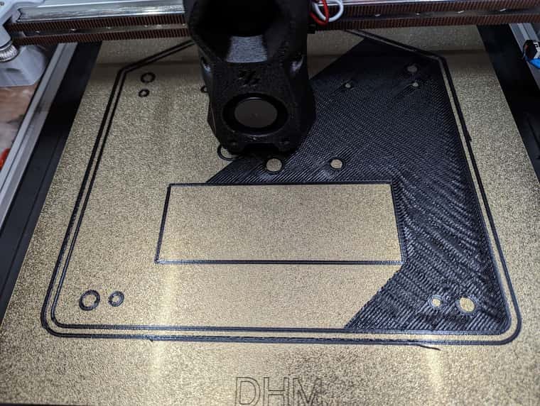
-
@Wobi while you can put movement commands in config.g, generally we don’t recommend automatic homing, heating or movement to be put in config.g, mainly because the state of the machine may be unknown at power on. What if there has been a power cut during print, or you did an emergency stop (effectively a reset) because of a problem?
For the temperature setting problem, I expect Prusa slicer is putting in the temperature that you have set for the filament, which may be 0C. Post the first 50 or so lines of a GCode file, up to where the G1 move commands start, so we can see what it is doing.
I successfully connected 7 RGB LEDs to my Mini 5+, using the ‘led’ header and pin name. I connected 5V and ground to an IO header, as these were quite low power LEDs (30mA each, so about 0.2A, within the 5V regulator’s capability). Please check your firmware version by sending M115 and post the result. Also post a link to the LEDs you are using (same as my link earlier?) and post a picture of how they are wired, and finally post the M950 code you’re using to configure them and M150 code to turn them on. Also send M98 P"config.g" in the console, and see if it produces any errors.
Ian
Bed-slinger - Mini5+ WiFi/1LC | RRP Fisher v1 - D2 WiFi | Polargraph - D2 WiFi | TronXY X5S - 6HC/Roto | CNC router - 6HC | Tractus3D T1250 - D2 Eth
-
@droftarts
Thank you for your quick and competent answer.
Your arguments are convincing, thank you, I'll leave it that way.
I can't say which LEDs are installed, they are not specified in the invoice, but they are RGBW LEDs that were completely soldered and all lines have continuity to all three LEDs, but I was only able to measure the data line up to the first LED.
I will deliver everything else when the printer has hopefully completed its print job tomorrow morning without any errors. -
@Wobi Change the Q parameter in this line:
M950 E0 C"led" T2 Q800000back to Q3000000. I've found that my LEDs don't work correctly with Q800000. I mistakenly thought Q was the bits per second rate, but it is the SPI clock frequency, which is 4x the bit rate, hence 800000 x 4 is 3200000. 3000000 is just below this, and has been check that it works fine on most LEDs.
For reference, I use:
M950 E1 C"led" T1 Q3200000
M150 E1 R255 S3 F0 ; sets first 3 LEDs to red
Ian
Bed-slinger - Mini5+ WiFi/1LC | RRP Fisher v1 - D2 WiFi | Polargraph - D2 WiFi | TronXY X5S - 6HC/Roto | CNC router - 6HC | Tractus3D T1250 - D2 Eth
-
@droftarts
Hello Ian,
Thanks, I can't try that until tomorrow.
To which pins did you connect the LEDS, to the Neopixel pins (do) directly next to the power connection of the Mini5 or directly to the 1LC and where exactly?
And have you connected an external power supply and if so where? Everything please, please with a photo.
I have attached a shortened G-code file of the Prusa Slicer.
Thank you for your patience and perseverance.wolfgang
Grundplatte_teil2_02.gcode -
@Wobi I’ll wire up 3 RGBW lights tonight. This is how I wired up the RGB leads:
The strips have 3 connections; 5V, data and GND. I connected 5V and GND to the 5V and GND on IO_4. I connected data to the led pin on the LED connector by power in. I don’t have anything connected to 5V_EXT, and no jumpers on the 5V_Select or internal_5V_disable pins. So the LEDs are powered from the internal 5V regulator, which can supply 1A. 3 LEDs should pull maximum 0.24A, so unless you’re running something else on 5V (PanelDue and 12864 screen etc) as well (I ran a PanelDue on mine as well, no problem), this should be fine. You can also just turn on LEDs at low brightness, to reduce current usage.
Make sure the data line connects to Di (data in) on the first LED, not Do (data out). If you can post a picture, that would help.
Ian
Bed-slinger - Mini5+ WiFi/1LC | RRP Fisher v1 - D2 WiFi | Polargraph - D2 WiFi | TronXY X5S - 6HC/Roto | CNC router - 6HC | Tractus3D T1250 - D2 Eth
-
@droftarts said in Duet3 Mini5+ Ethernet Nozzle Distance to PEI sheet is too large:
12864
I have a 12864 display
-
@Wobi
Good morning Ian,
I've now measured again and I couldn't measure any voltage, the voltmeter shows 0 volts at the pins.
To be on the safe side, I also measured with the display disconnected, still 0 volts on + and -.
An external power supply was also unsuccessful, regardless of whether I supplied the board with 5 volts using the pin next to it or applied the 5 volts directly to the LEDs.
It seems like the DO pin is not outputting a signal.
Did I even use the correct pins for the Stealthburner LEDs or do I have to connect them somewhere completely different?Printing now works fine and fairly quickly. That's actually the main thing.
The cause of the crash was probably a larger blob on which the nozzle got stuck, it only has an M5 thread and is hollow inside, so not very stable.Another request, by repeatedly unplugging and plugging in the fan plug on the 1LC board, the cables broke off and now I also ran out of small pins to re-crimp.
Could you please tell me the exact name of the small pins so that I can get some?Thank you, Wolfgang
-
@Wobi I've now got RGB and RGBW LEDs working on Mini 5+, 6HC and Duet 2 WiFi, on both the dedicated 5V signalling 'led' pin, as well as 3.3V signalling pins like io_#.out. It should really not be difficult!
First, please send
M115in the terminal so I can check you are using the correct firmware; I know you said you updated, but please send this to check.On the Mini 5+, the NEOPIXEL header is only powered by External 5V; you can't power your LEDs from that header. However, the DO pin is active, and provides a 5V signal (not constant, only when you send an M150 command). So you need to connect the +5V and GND of the LEDs to somewhere else. If you only have 3 LEDs, you should be okay to use 5V from the Duet itself. I don't think the 12864 display draws that much current, so you should be okay to leave that connected.
So connect the LED +5V and GND to an IO header, or anywhere else that has a 5V pin and GND. Then connect the data wire to DO pin on the NEOPIXEL header. If you have a LED string configured for the 12864, make sure you're using different M950 E# numbers for each.
Let me know if that helps. If not, I'll take a picture of my setup. Also, please post a picture of your LEDs.
Ian
Bed-slinger - Mini5+ WiFi/1LC | RRP Fisher v1 - D2 WiFi | Polargraph - D2 WiFi | TronXY X5S - 6HC/Roto | CNC router - 6HC | Tractus3D T1250 - D2 Eth
-
@droftarts
Good morning Ian, the ones that were already installed still don't work, they are probably defective. I have now temporarily connected a new 2 euro set and after entering your GCodes the first one lights up red, the second green and the third doesn't light up at all. Power supply via the 5v PWM+, see photo. However, I only measure 3.6 volts on the third LED and after the ground PIN of the LEDs is broken, both of them continue to light up and I measure 5 volts on all LEDs again. So I will use an external power supply.
Which LEDs should I order or can I use the 2 euros?
And please, where can I order connectors for the 1LC board?
Thanks Ian
wolfgang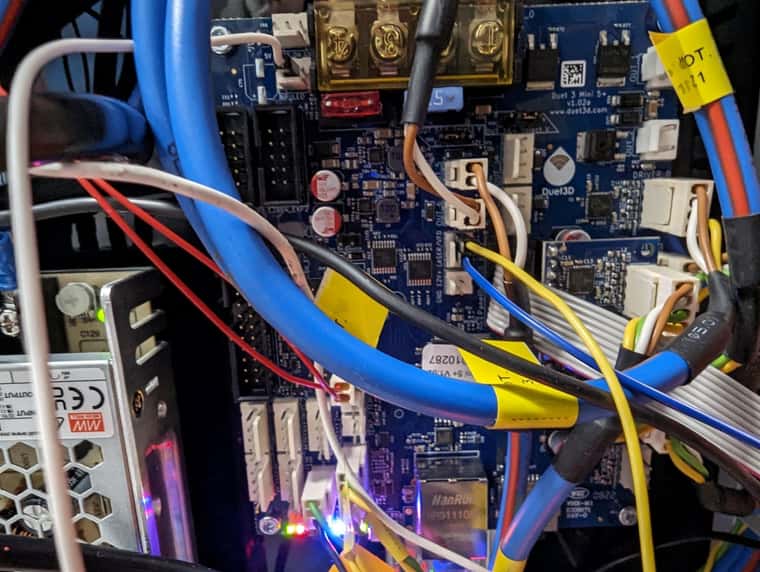
-
@Wobi Are the 5V power and GND the Blue and Yellow wires? If so, you've plugged 5V (blue) into 5V_EXT (which should be okay), but the yellow GND wire into 'out6_buff', not GND!
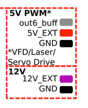
Move the yellow wire to a proper GND pin.
Ian