4 Axis Z - Setup
-
Greetings,
I am making a large printer (1800mm^3), my first duet setup and would like some feedback if I am getting my axis setup properly.
I have 4 Z lead screws, and 2 Y rack and pinions:
Does this syntax look right for defining the drives for my 8 Axises?? The docs on how to map the drives were a bit confusing, so I am hoping I got this right.
; Drives on Duet3 6XD board
M569 P0.0 S1 ; X physical drive 0.0 goes forwards
M569 P0.1 S1 ; Y1 physical drive 0.1 goes forwards
M569 P0.2 S0 ; Y2 physical drive 0.2 goes Reverse
M569 P0.3 S1 ; Z1 physical drive 0.3 goes forwards
M569 P0.4 S1 ; Extruder physical drive .4 goes forwards; Drives on Duet3 3HC board
M569 P1.0 S1 ; Z2 physical drive 1.0 goes forwards
M569 P1.1 S1 ; Z3 physical drive 1.0 goes forwards
M569 P1.3 S1 ; Z4 physical drive 1.0 goes forwards; Configure axises
M584 X0.0 Y0.1:0.2 Z0.3:1.0:1.2:1.3 E0.2 ; set drive mappingThe next question is in regard to endstops. Again, does this syntax look reasonable?
; Endstops
M574 X1 S1 P"io0.in" ; X Endstop on 6XD board
M574 Y1 S1 P"io1.in" ; Y Endstop on 6XD board
M574 Y2 S1 P"io2.in" ; Y Second Axis Endstop on 6XD boardM574 Z1 S1 P"1.io0.in" ; Z Axis Endstop on 6XD board
M574 Z2 S1 P"1.io1.in" ; Z Second Axis Endstop on 6XD board
M574 Z3 S1 P"1.io2.in" ; Z Third Axis Endstop on 6XD board
M574 Z4 S1 P"1.io3.in" ; Z Fourth Axis Endstop on 6XD boardReally appreciate the help!
Scott
-
@Snyggis-0 Your motor setup looks okay. Your endstop setup is wrong, though. See M574 and https://docs.duet3d.com/User_manual/Connecting_hardware/Z_probe_auto_levelling#axis-levelling-using-endstops
You don't number the endstops with the axis letter. The number defines the position of the endstop on the axis: 0 = none, 1 = low end, 2 = high end
To define an axis with multiple endstops, you add them together into one expression:; Endstops M574 X1 S1 P"io0.in" ; X Endstop on 6XD board M574 Y1 S1 P"io1.in+io2.in" ; Y Axis Endstops on 6XD board M574 Z1 S1 P"1.io0.in+1.io1.in+1.io2.in+1.io3.in" ; Z Axis Endstops on 3HC boardMake sure that the endstops are defined in the same order in the M574 command as the corresponding motors in your M584 command, ie 1.io0.in is the endstop for the motor connected to driver 0.3, 1.io1.in is the endstop for driver 1.0 etc.
When homing, RRF3 will home all axes, and stop each motor when each endstop is triggered.
Ian
Bed-slinger - Mini5+ WiFi/1LC | RRP Fisher v1 - D2 WiFi | Polargraph - D2 WiFi | TronXY X5S - 6HC/Roto | CNC router - 6HC | Tractus3D T1250 - D2 Eth
-
@droftarts Awesome! Thanks for the help.
A few more questions. It looks like the web tool automatically made me a few homing programs:
; generated by RepRapFirmware Configuration Tool v3.3.16 on Fri Nov 17 2023 14:07:11 GMT-0500 (Eastern Standard Time)
G91 ; relative positioning
G1 H2 Z5 F6000 ; lift Z relative to current position
G1 H1 Z1105 F1800 ; move Z up until the endstop is triggered
G92 Z1100 ; set Z position to axis maximum (you may want to adjust this)Running this code should drive all of the Z axis into their homing switches?
-
Where are you endstops? At the low end (Z min) or the high end (Z max)?
The homing moves G1 H1 must be in the correct direction.
Frederick
-
Ok, looking at this it is a bit more complicated.
X and Y - I am using servo motors. They have a "Home to hard stop" feature. This is done by driving an IO high on the servo drive and once it has completed homing the servo drive will output a signal to indicate homing complete.
I believe this is what I am trying to accomplish:
- Drive all 4 Z stepper motors up to their top end stops. This gets the head out of the way for homing X and Y.
- Home X and Y
-
Activate IO to commence homing
-
Wait for an IO to go high to confirm homing complete
So far does this sound reasonable? It is a large gantry and I want the z as square as possible. Would it make sense to then go down with a z probe and find the position of the table and measure its flatness?
-
I don't understand the following:
"drive all 4 Z steppers up to their top ends" - normally you would move the bed down to get it away from the nozzle so you could do homing.
Since you have installed 4 Z endstops why don't you simply home Z using G1 H1 commands and when Z is homed you can move it to a safe location (say Z=10) for homing X and Y?
How does the "home to hard stop" feature enter into this? Is it something that has to be done before you can use the servos for normal G1 movments?
Frederick
-
@fcwilt I'm guessing the bed doesn't move, but the X and Y axes are lifted by Z, like a Voron 2.4. Is that correct @Snyggis-0 ?
Ian
Bed-slinger - Mini5+ WiFi/1LC | RRP Fisher v1 - D2 WiFi | Polargraph - D2 WiFi | TronXY X5S - 6HC/Roto | CNC router - 6HC | Tractus3D T1250 - D2 Eth
-
Moving the XY gantry instead of the bed????
That's almost as bad as setting 0,0 at the left front corner!

Frederick
-
@fcwilt
Ha! Well.. looks like I could use some advice here. Please have a look at the pictures for perspective. This is my first experience with Duet and I'm learning.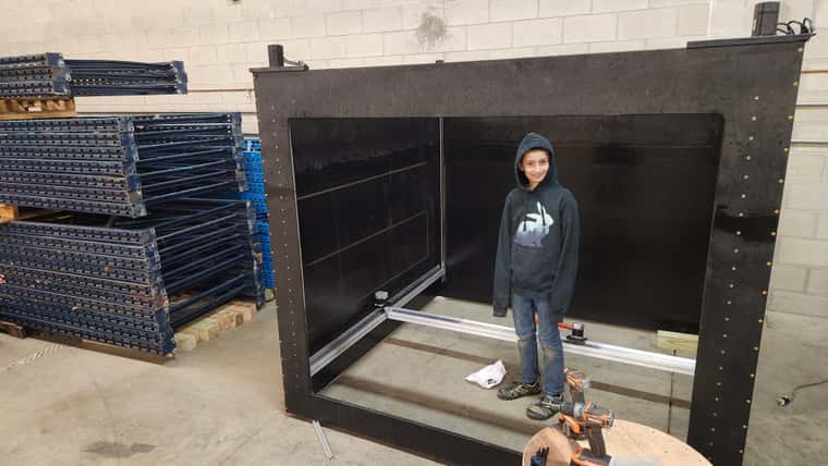
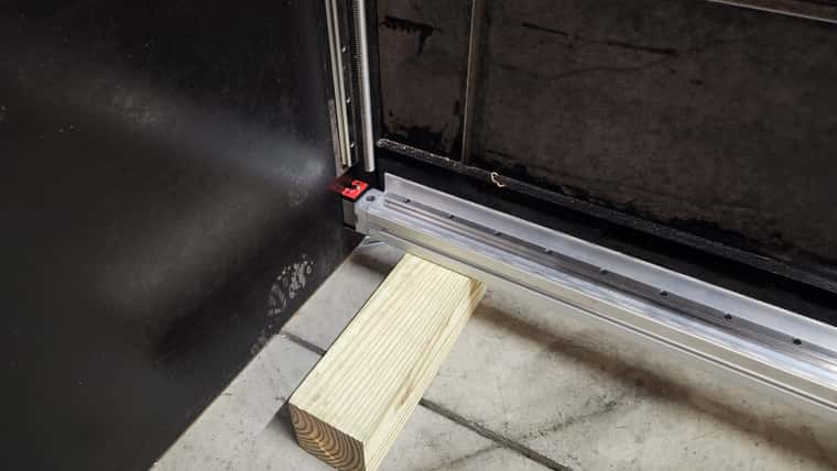
1800mm cubic volume, the gantry moves with the light weight print head. The glass plate is fixed at the bottom. You can see the 4 stepper motors in each corner, there is a lead screw which raises and lowers each side. I was imagining a homing program where they all move up in z until they hit the switches. If there is a better way to do this I am WIDE open to suggestions?? Struggling to think of how to get each corner level.
I am using ClearPath servos for the X and Y Axis.
https://teknic.com/model-info/CPM-SDHP-2310S-ELN/?model_voltage=75VDCThey have a nice feature where they move at a reduced torque into a hard stop. I was thinking of bumping the X/Y into stops and setting the position at -900mm for both X and Y. Is there a better way of doing this?
Thanks for your advice!
-Snyggis
-
You certainly can use the 4 Z steppers when you have "matching" 4 Z endstops to level the bed BUT it depends on getting the Z endstops into the exact positions to obtain a level bed.
It is easier to just get the positions of the Z endstops close so the bed, after homing, is more or less level and THEN use Auto Bed Leveling (the G32 command which runs your bed.g file) which probes the bed in 4 locations (in your case) and adjusts the Z steppers to achieve a perfectly level bed.
Here is an example of a bed.g file to do Auto Bed Leveling:
; ------------------------------------------------------------------ ; --- example of bed.g to do auto bed leveling with 4 Z steppers --- ; ------------------------------------------------------------------ M290 R0 S0 ; clear baby stepping G29 S2 ; cancel mesh bed compensation ; --- specify where Z leadscrews are --- ; M671: Define positions of Z leadscrews ; Xnn:nn:nn:nn... list of 4 X coordinates of the pivot points of the gantry where it connects to the Z axis ; Ynn:nn:nn:nn. list of 4 Y coordinates of the pivot points of the gantry where it connects to the Z axis ; Snn maximum correction allowed for each leadscrew in mm (optional, default 1.0) ; Fnn fudge factor, default 1.0 ; *** important *** ; Xaaa and Yeee are for the 1st Z stepper in your M584 command ; Xbbb and Yfff are for the 2nd Z stepper in your M584 command ; Xccc and Yggg are for the 3rd Z stepper in your M584 command ; Xddd and Yhhh are for the 4th Z stepper in your M584 command M671 Xaaa:bbb:ccc:ddd Yeee:fff:ggg:hhh ; replace the letters with the actual values for your machine ; --- level bed --- while true ; run leveling pass ; --- probe near bed corners --- again replace the letters with the actual values for your bed G30 P0 Xaaa Ybbb Z-99999 ; probe near LF corner G30 P1 Xccc Yddd Z-99999 ; probe near LR corner G30 P2 Xeee Yfff Z-99999 ; probe near RR corner G30 P2 Xggg Yhhh Z-99999 S4 ; probe near RF corner ; check results - exit loop if results are good if move.calibration.initial.deviation < 0.02 set var.success = true break ; check pass limit - exit loop if pass limit reached if iterations = 5 set var.success = false break ; --- end of while loop --- ; --- set the Z=0 Datum --- G90 G1 Xaaa Ybbb F6000 ; move probe to bed center G30 -
@fcwilt Makes sense. In the case of an error where the part is stopped mid print, you have to remove the part. I suppose this is inevitable if you want to re-zero the bed.
Questions:
Endstop positions - should be slightly above the bed?
Z Probe - Do you have any suggestions for a machine like this?I
-
@Snyggis-0 said in 4 Axis Z - Setup:
Endstop positions - should be slightly above the bed?
Yes 10 mm should be adequate. You just don't want to damage anything by colliding with the bed.
Z Probe - Do you have any suggestions for a machine like this?
What is the bed made out of? What type of surface are you going to print on?
Frederick
-
@fcwilt I am planning on a large tempered glass surface.
-
I think you are pretty much limited to a BLTouch-like device or a removable micro-switch like a Euclid.
You might find a inductive that would have enough range to "reach" through the glass to the metal below - assuming there is metal below.
Capacitive units would work with the glass but all the ones I have seen and tested had a slow response time meaning a rather low probing speed to obtain reasonable accuracy.
Frederick
-
@Snyggis-0 I'm going to disagree with @fcwilt here. I think you should have your Z endstops at the opposite end of Z from the bed. Reason? You have a very big printer. Big prints take a long time. Power failures are more likely. You don't want the only way of re-levelling the XY gantry to be close to the bed.
I'd have adjustable endstops at the high end of Z. Initially home Z to them, then run a four-point bed calibration (G32 - see https://docs.duet3d.com/User_manual/Connecting_hardware/Z_probe_auto_levelling). Adjust the endstops so that subsequent G32s cause no change. You will also have to accurately set the Z height. That should allow you to restart a print job following a power failure. Repeat every so often to check accuracy. You could do this with Z stalling, but it's often less accurate on screw driven axes, and harder to dial in.
You don't always need to use these endstops for regular Z homing; whatever probe you use should be sufficient, and will save lifting the gantry up and down a lot.
Ian
Bed-slinger - Mini5+ WiFi/1LC | RRP Fisher v1 - D2 WiFi | Polargraph - D2 WiFi | TronXY X5S - 6HC/Roto | CNC router - 6HC | Tractus3D T1250 - D2 Eth
-
I absolutely agree with your thoughts if your concern is power failures.
I don't like power failures for variety of reasons.
So my approach was to install a propane powered generator with automatic transfer plus dual-conversion UPS units with enough runtime to power the printers until the generator kicks in, which is typically 30 seconds.
Overkill? Probably but its nice to have power that doesn't go away because a storm rolls in. I will admit that I only have enough propane in the tank for 10 days, so a serious power outage due to say, storm damage, may mean I will lose power.
Moving the endstops is a much cheaper solution.

Frederick