G32 doesnt save after True Bed Leveling
-
@fcwilt said in G32 doesnt save after True Bed Leveling:
In any case you have been using G32 to do automatic bed leveling using the two Z steppers.
I don't have mesh.g can you share it please?
-
@fcwilt said in G32 doesnt save after True Bed Leveling:
It seems the config utility doesn't adhere to the intended use of these two files and may put the code that should be in mesh.g into bed.g as well.
The config utility can't create an axis with multiple motors, so it can't produce a bed.g for independent levelling. So it creates a bed.g with the commands to do bed mesh levelling. I generally use bed.g for mesh levelling, and have macros for 2-point gantry levelling and 3-point manual bed levelling (using levelling screws, see https://docs.duet3d.com/en/User_manual/Connecting_hardware/Z_probe_manual_levelling). mesh.g was introduced with RRF 3.2. I've updated the Gcode page to make mesh.g a bit clearer: https://docs.duet3d.com/en/User_manual/Reference/Gcodes#meshg
@johny example mesh.g
M561               ; clear any bed transform
G28                ; home all
G29 S0             ; probe the bed and enable compensation
G1 X160 Y160 F6000 ; move to bed centre
G28 Z              ; home Z to set Z datum
Ian
Bed-slinger - Mini5+ WiFi/1LC | RRP Fisher v1 - D2 WiFi | Polargraph - D2 WiFi | TronXY X5S - 6HC/Roto | CNC router - 6HC | Tractus3D T1250 - D2 Eth
-
@johny said in G32 doesnt save after True Bed Leveling:
I don't have mesh.g can you share it please?
I can provide an example mesh.g file for creating the height map used for Mesh Compensation, using G29.
The only thing "special" about bed.g and mesh.g is that there is the command G32 which runs bed.g and G29 which runs mesh.g (if it exists).
I recommend using them as intended which keeps the DWC interface "in sync" with your code.

You could put the code for bed leveling or height map creation in any file at all - they simply won't be run using G32 or G29.
Would you like the example mesh.g file?
Frederick
-
@droftarts This mesh.g is a non-ending loop

I am in a death end
I don't know what to do next, get a new bed? the firmware should compensate the difference on a 130mm cube its not even on the entire bed, its on a small 130mm cube
I still believe there is something wrong with software, its not hardware -
@johny Ooops! Sorry, the line should be
G29 S0 ; probe the bed and enable compensationNot just G29, because
In RRF 3.2 and later, if G29 is commanded with no S parameter, then file sys/mesh.g is run if it exists.
If you emergency stop, you should be able to get control back, then change the macro
Ian
-
@johny Did you ever do a mesh by hand? You might believe it's software, but many, many users use bed mesh without problems. I think the problem is the distance the probe is from the nozzle, and they are measuring different things. Probably your bed is flatter than the probe is reporting. You didn't answer my question earlier about the position of the probe, or if you had checked the bed with a straight edge, like a ruler.
Ian
Bed-slinger - Mini5+ WiFi/1LC | RRP Fisher v1 - D2 WiFi | Polargraph - D2 WiFi | TronXY X5S - 6HC/Roto | CNC router - 6HC | Tractus3D T1250 - D2 Eth
-
@droftarts
As i understood to make the mesh manually the nozzle will travel to the first position then it waits for me to jog the Z and then I should click somewhere or send some command right? i tried to look for this and didn't found.
I have 3D printers since 2011 and i followed the innovations closely. I have a Cartesian (duet) with BLtouch that works fine, i don't touch the bed for years.
Maybe I need to flash the duet again? -
You have a Z probe and it seems to be working. No point in creating a height map by hand when you have a Z probe.
Refresh my memory - did you ever verify that the Z trigger height setting in the G31 was correct?
You won't get a good height map if that setting is wrong.
Frederick
-
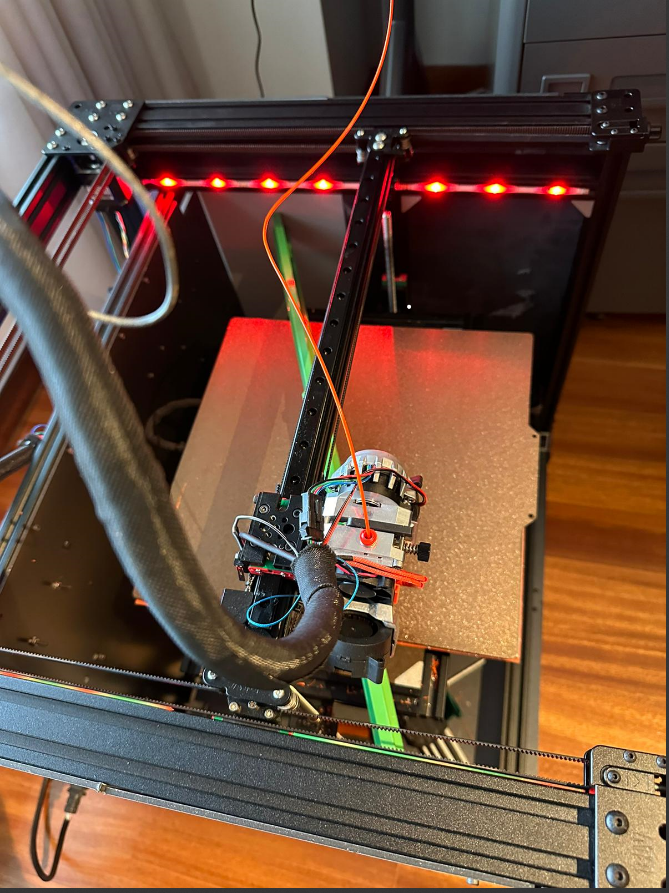
@johny can you take a couple more pictures of your X carriage, ie from the side?
Have you put a straight edge across your bed?Either the bed is warped, or there’s a difference between what the probe is measuring and how fat the nozzle is from the bed, dependant on the position on the axis.
As I said earlier, for the manual bed probe, use a piece of paper under the nozzle at each point. Move the Z down until it just grabs the paper. Click OK to move on to the next point.
@fcwilt you have missed the point. The probed bed mesh doesn’t match what the nozzle is doing. Getting a manual bed mesh, the comparing it to a probe bed mesh, should show what the difference is. I think the bed is very likely has less deviation than 0.65mm, and the problem is caused by the gantry twisting under the weight of the hotend. Because I think the probe is offset in the Y direction (though the config does not reflect this) it is mismeasuring the mesh.
Ian
Bed-slinger - Mini5+ WiFi/1LC | RRP Fisher v1 - D2 WiFi | Polargraph - D2 WiFi | TronXY X5S - 6HC/Roto | CNC router - 6HC | Tractus3D T1250 - D2 Eth
-
I understand your point. I simply don't agree with your theory as to what is wrong.
Getting past "operator error" can be tricky.

Frederick
-
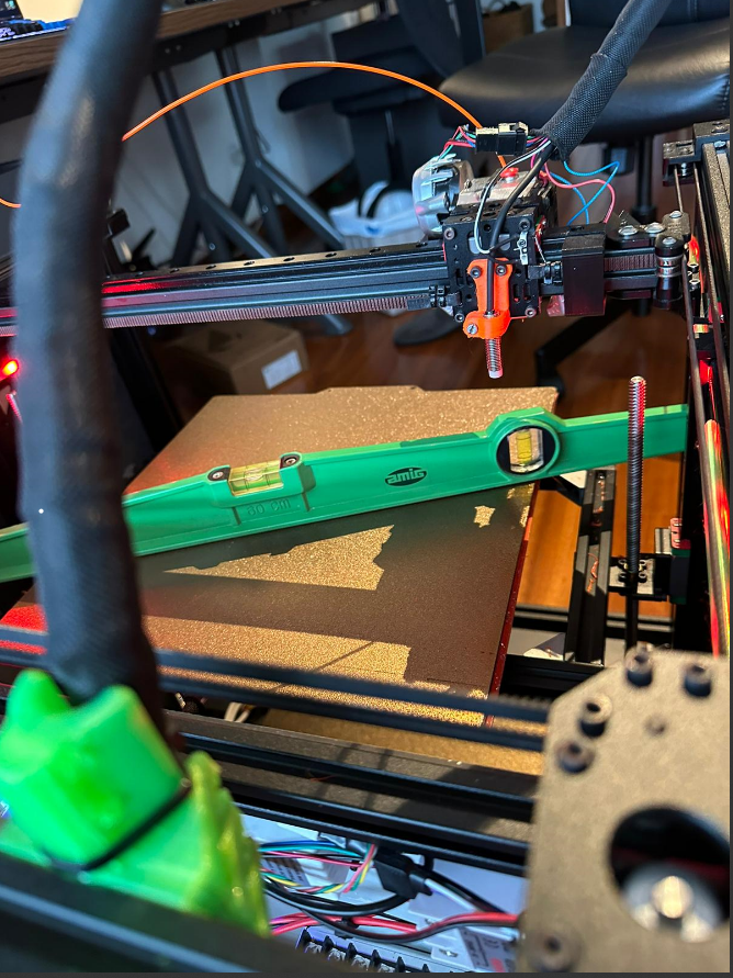
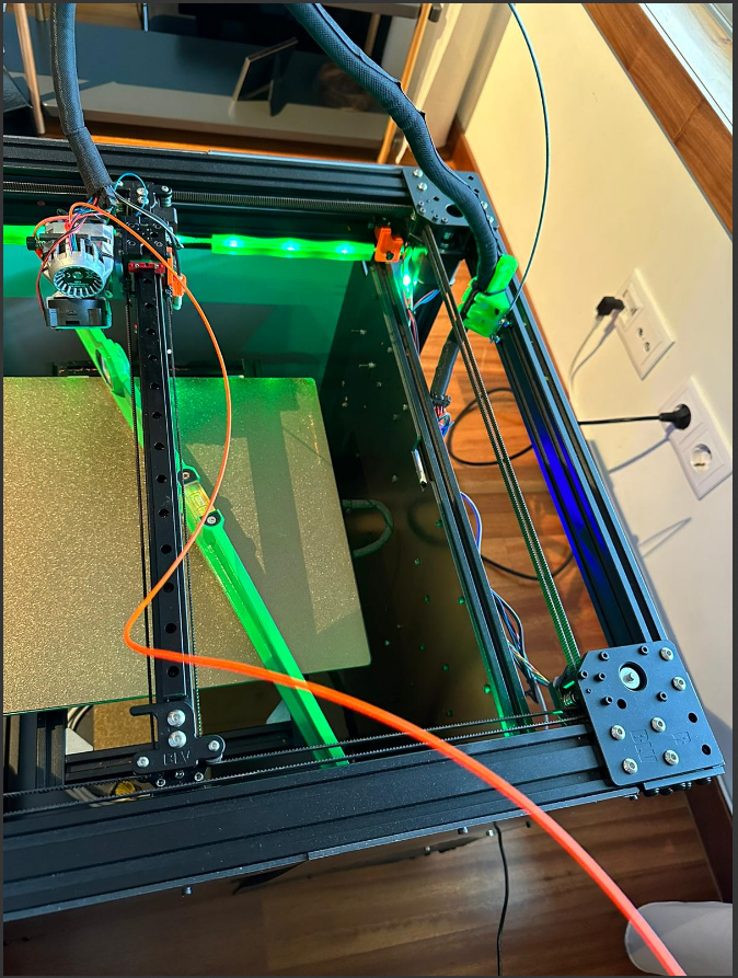
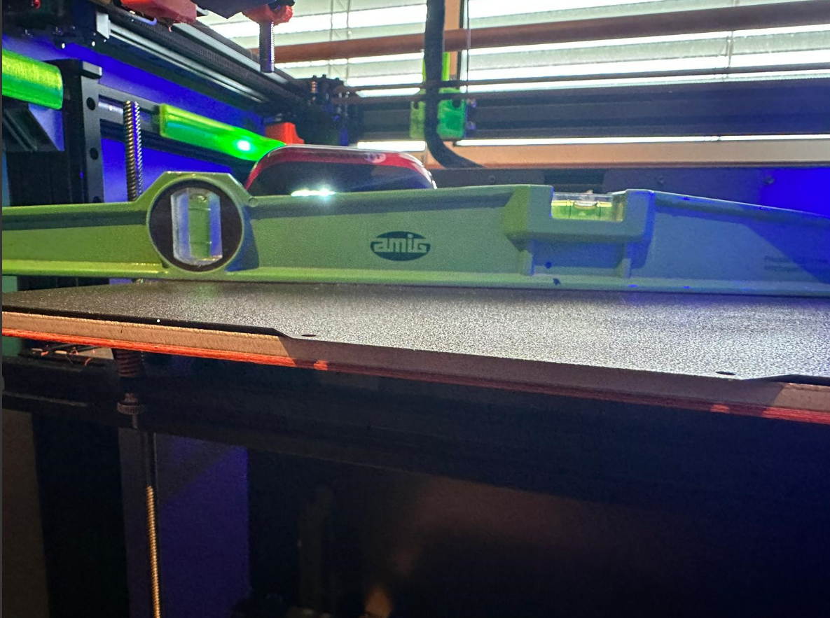
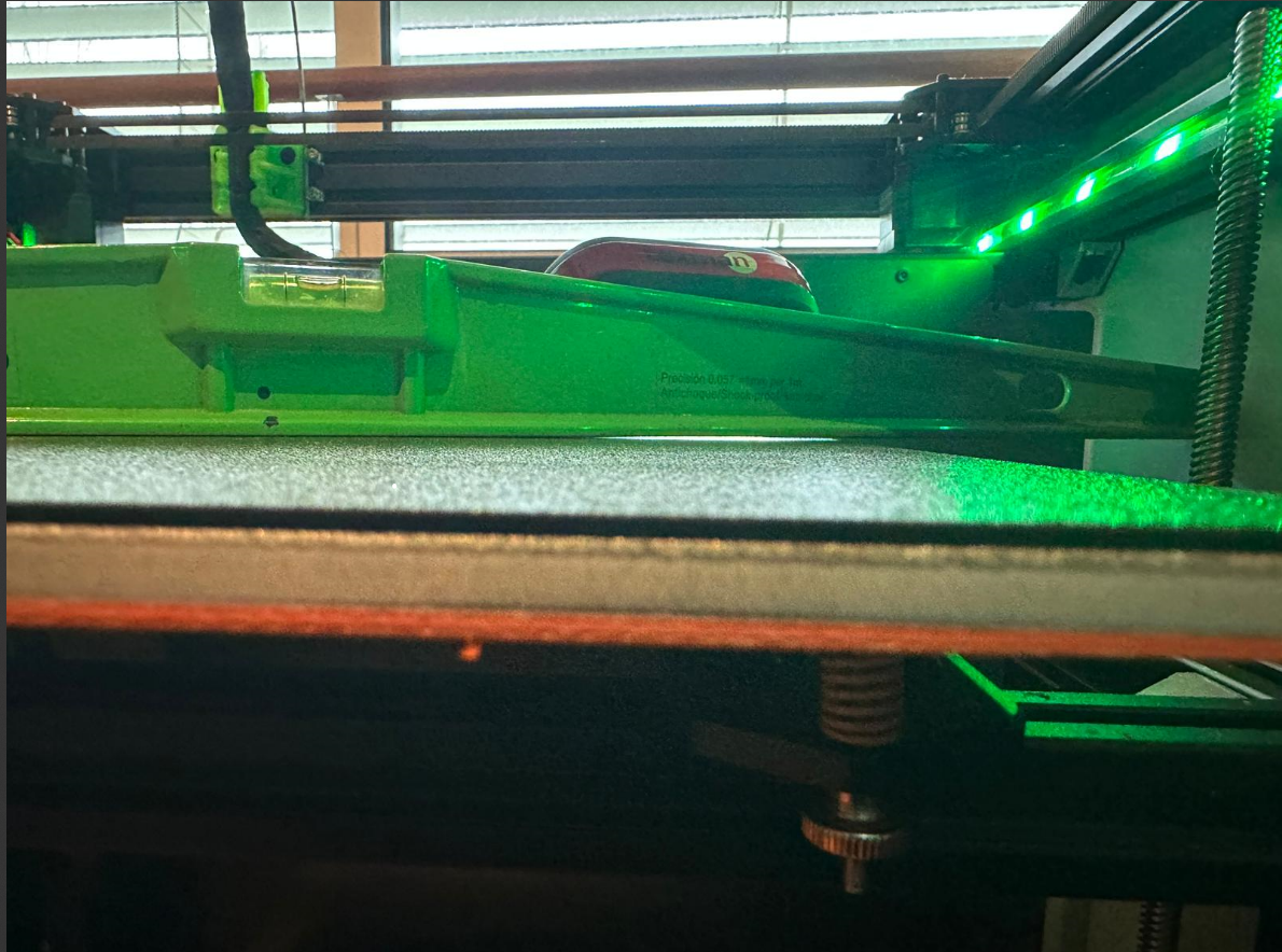
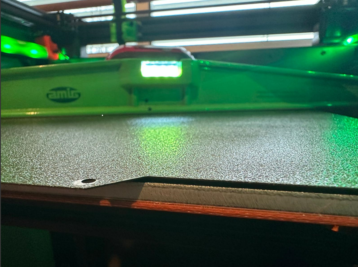
@droftarts Sorry for the late reply, with the end of the year/vacations, etc I didn't have the proper time to reply and work on this printer problem. Bellow the pictures asked.
The bed is warped (I used a light source below the ruler to see it better but the bed compensation should compensate for that no?)
-
@johny with the wrong Y offset of the probe, the compensation applied is wrong.
An exaggerated example: If your Y offset is 40mm physically but you defined your Y offset as 0 in your config, the printer will compensate for what it measured 40mm away
In addition, the further away the probe is from the nozzle, the higher the risk for imperfections in the carriage and probe mount skewing results further.
The recommendations are
a) verify and adjust your Y offset
b) try to reduce the distance between nozzle and probe (verifying and adjusting probe offsets after)In addition, I recommend to have the Z probe location match a point of your axis alignment and a point of your bed mesh, so you have a physical fix point between the three measurements that should not be further out than your probe repeatability.
-
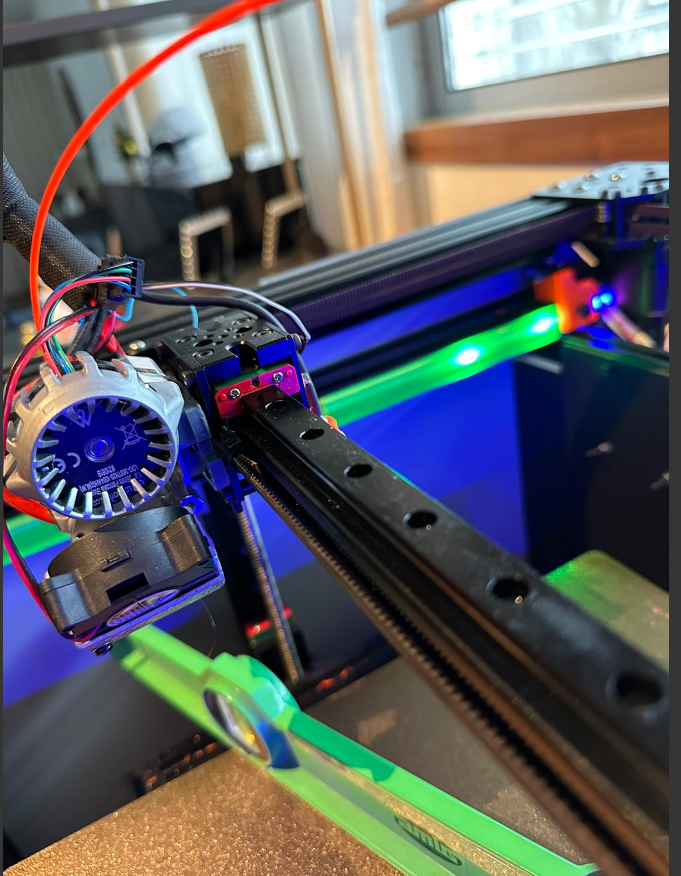
@oliof so you saying that G31 has the wrong X and Y values?
G31 P1000 X23 Y5 Z0.1 -
@johny I would guess that the center of the probe is rather 50mm away from the nozzle than 5mm in the Y direction guessing from the photo you posted. after all, you have a 20mm extrusion between the two, and both the Z probe and the nozzle stick out. So yeah, that's likely off by a lot.