Mirror printing issue
-
Hello,
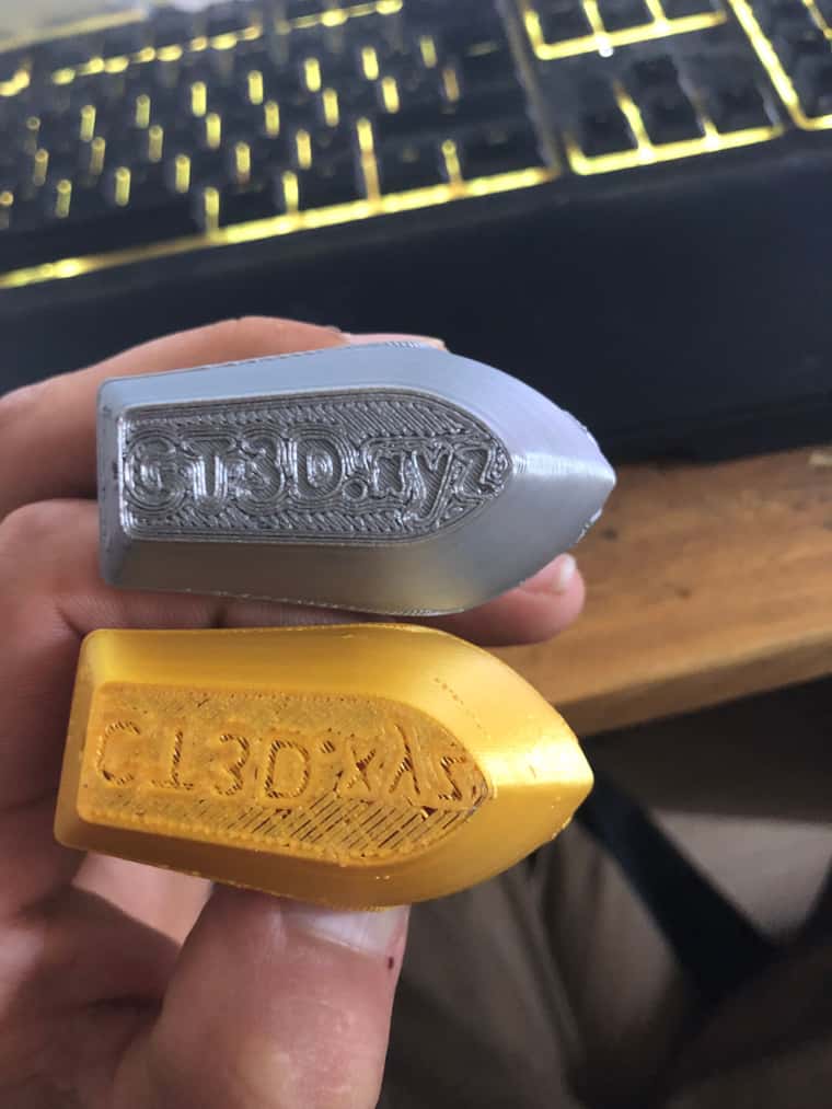
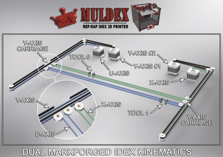
I am currently building a "MarkForged IDEX" type 3D printer based on the Muldex project. The problem is as follows: the print starts well, but once finished, the writings under the 3DBenchy are mirrored. It seems to me that the Y-axis is inverted. What do you think?
PS: In yellow, the problematic boat; in gray, the correct example.
Bonjour,
Je suis actuellement en train de construire une imprimante 3D de type "MarkForged IDEX" à partir du projet Muldex. Le problème est le suivant : l'impression démarre bien, mais une fois terminée, les écritures sous le 3DBenchy sont en miroir. Il me semble que c'est l'axe Y qui est inversé. Qu'en pensez-vous ?
PS : En jaune, le bateau avec problème ; en gris, le bon exemple.
; General G90 ; absolute coordinates M83 ; relative extruder moves M550 P"MuldeX V 0.1" ; set hostname ; Accessories M575 P1 S1 B57600 ; configure PanelDue support ; Network M551 P"" ; set machine password M552 S1 ; configure WiFi adapter M586 P0 S1 ; configure HTTP ; Smart Drivers M569 P0 S0 D2 ; driver 0 goes forwards (X axis) M569 P1 S0 D2 ; driver 1 goes forwards (Y axis) M569 P2 S1 D2 ; driver 2 goes forwards (Y axis) M569 P3 S0 D2 ; driver 3 goes backwards (U axis) M569 P4 S0 D2 ; driver 4 goes forwards (Z axis) M569 P5 S0 D2 ; driver 5 goes forwards (Z axis) M569 P6 S1 D2 ; driver 6 goes forwards (extruder 0) M569 P7 S1 D2 ; driver 7 goes forwards (extruder 1) M569 P8 S1 D2 ; driver 8 goes forwards (Z axis) M569 P9 S1 D2 ; driver 9 goes forwards (Z axis) ; Motor Idle Current Reduction M906 I30 ; set motor current idle factor M84 S30 ; set motor current idle timeout ; Axes M584 X0 Y1:2 Z4:5:8:9 U3 ; set axis mapping M350 X16 Y16 Z16 U16 I1 ; configure microstepping with interpolation M906 X500 Y500 Z500 U500 ; set axis driver currents M92 X80 Y80 Z400 U80 ; configure steps per mm M208 X0:574 Y0:320 Z0:400 U0:574 ; set minimum and maximum axis limits M566 X900 Y900 Z12 U900 ; set maximum instantaneous speed changes (mm/min) M203 X6000 Y6000 Z1800 U6000 ; set maximum speeds (mm/min) M201 X500 Y500 Z20 U500 ; set accelerations (mm/s^2) ; Extruders M584 E6:7 ; set extruder mapping M350 E16:16 I1 ; configure microstepping with interpolation M906 E500:500 ; set extruder driver currents M92 E420:420 ; configure steps per mm M566 E120:120 ; set maximum instantaneous speed changes (mm/min) M203 E3600:3600 ; set maximum speeds (mm/min) M201 E250:250 ; set accelerations (mm/s^2) ; Kinematics M669 K11 Y-1:1:0:1 ; configure MarkForged kinematics ; Probes M558 K0 P9 C"^zprobe.in" H5 F800 T6000 ; configure BLTouch probe via slot #0 G31 P500 X0 Y0 Z0.7 ; set Z probe trigger value, offset and trigger height M950 S0 C"duex.pwm2" ; create servo #0 for BLtouch ; Endstops M574 X1 P"xstop" S1 ; configure X axis endstop M574 Y1 P"ystop+zstop" S1 ; configure Y axis endstop M574 Z2 S2 ; configure Z axis endstop M574 U1 P"duex.e2stop" S1 ; configure U axis endstop ; Mesh Bed Compensation M557 X75:574 Y75:270 S20:20 ; define grid for mesh bed compensation ; Sensors M308 S0 P"e0temp" Y"thermistor" A"Nozzle 0" T100000 B4725 C7.06e-8 ; configure sensor #0 M308 S1 P"e1temp" Y"thermistor" A"Nozzle 1" T100000 B4725 C7.06e-8 ; configure sensor #1 M308 S2 P"bedtemp" Y"thermistor" A"Bed 0" T100000 B4725 C7.06e-8 ; configure sensor #2 M308 S3 P"duex.e2temp" Y"thermistor" A"Bed 1" T100000 B4725 C7.06e-8 ; configure sensor #3 M308 S4 P"duex.e3temp" Y"thermistor" A"chamber" T100000 B4725 C7.06e-8 ; configure sensor #4 ; Heaters M950 H0 C"e0heat" T0 ; create heater #0 M143 H0 P0 T1 C0 S285 A0 ; configure heater monitor #0 for heater #0 M307 H0 R2.43 D5.5 E1.35 K0.56 B0 ; configure model of heater #0 M950 H1 C"e1heat" T1 ; create heater #1 M143 H1 P0 T1 C0 S285 A0 ; configure heater monitor #0 for heater #1 M307 H1 R2.43 D5.5 E1.35 K0.56 B0 ; configure model of heater #1 M950 H2 C"bedheat" T2 ; create heater #2 M143 H2 P0 T1 C0 S110 A0 ; configure heater monitor #0 for heater #2 M307 H2 R2.43 D5.5 E1.35 K0.56 B0 ; configure model of heater #2 M950 H3 C"duex.e2heat" T3 ; create heater #3 M143 H3 P0 T1 C0 S110 A0 ; configure heater monitor #0 for heater #3 M307 H3 R2.43 D5.5 E1.35 K0.56 B0 ; configure model of heater #3 M950 H4 C"duex.e4heat" T4 ; create heater #4 M143 H4 P0 T1 C0 S60 A0 ; configure heater monitor #0 for heater #4 M307 H4 R2.43 D5.5 E1.35 K0.56 B0 ; configure model of heater #4 ; Heated beds M140 P0 H2 ; configure heated bed #0 M140 P1 H3 ; configure heated bed #1 ; Heated chambers M141 P0 H4 ; configure heated chamber #0 ; Fans M950 F0 C"fan0" ; create fan #0 M106 P0 S0 B0.1 H0 T45 ; configure fan #0 M950 F1 C"fan1" ; create fan #1 M106 P1 S0 B0.1 H1 T45 ; configure fan #1 ; Tools M563 P0 D0 H0 F0 ; create tool #0 M568 P0 R0 S0 ; set initial tool #0 active and standby temperatures to 0C M563 P1 D1 H1 F1 ; create tool #1 M568 P1 R0 S0 ; set initial tool #1 active and standby temperatures to 0C -
@404-print Was the grey one printed with tool 0 and the yellow one with tool 1? Or do you have a tool set up to print two at once? Your config.g only shows two tools, and neither are mapped to the U axis.
If you did print the yellow benchy with tool 2, and you mapped it to U, I think that U is working in the wrong direction. Because you have the endstop homing at the 'low' end:
M574 U1 P"duex.e2stop" S1 ; configure U axis endstopwhen it almost certainly needs to home on the right, at the high end. The X and U axes should both start with 0 at the left, and go up to 574 on the right.
If that's what is happening, you need to reverse the direction of the U axis in M569:
M569 P3 S0 D2 ; driver 3 goes backwards (U axis)So change S0 to S1. Then change the M574 homing to U2, then change the homeu.g to home the axis at the maximum end, not the minimum.
Ian
Bed-slinger - Mini5+ WiFi/1LC | RRP Fisher v1 - D2 WiFi | Polargraph - D2 WiFi | TronXY X5S - 6HC/Roto | CNC router - 6HC | Tractus3D T1250 - D2 Eth
-
@droftarts Thank you for your response. No, the grey model was printed with a different machine. The problem comes from the fact that I switched where the motors are connected to the belt. At least, I think so... I'll adjust that to check if it's rotating in the correct direction. But what do you mean by "neither are mapped to the U axis"?
Merci pour ta réponse. Non, le modèle gris a été imprimé avec une autre machine. Le problème vient du fait que j'ai inversé l'endroit où les moteurs sont raccordés à la courroie. Du moins, je pense... Je vais modifier cela pour vérifier si c'est bien dans le bon sens de rotation. Par contre, que veux-tu dire par "aucun d'eux n'est mappé à l'axe U" ?
-
@404-print said in Mirror printing issue:
The problem comes from the fact that I switched where the motors are connected to the belt.
Okay. You are just trying to print with one tool, tool 0, first? Most likely the Y motor is going the wrong direction, and is homing at the wrong end. X0 Y0 should be with the nozzle/tool at the front left corner of the bed ideally. It can also be in the centre, or the back right, but to start with it's easiest if you set it front left. A positive X move should move the nozzle/tool to the right, and a positive Y move should move the nozzle/tool towards the back of the bed.
At least, I think so... I'll adjust that to check if it's rotating in the correct direction.
For getting things moving in the correct direction, see https://docs.duet3d.com/en/User_manual/Connecting_hardware/Motors_testing#checking-movement-direction
You will probably need to also change the Y endstop location to the high end, egM574 Y2 P"ystop+zstop" S1, and change your homeall.g and homey.g macros so that it homes to Y maximum, not Y0.But what do you mean by "neither are mapped to the U axis"?
I assume you are only getting the first tool working at the moment. When you want to get the second tool working, you need to map the U axis to X, so that when you select tool 1 (your first tool is tool 0), X moves move the U axis, and so tool 1. See the IDEX wiki page for more details: https://docs.duet3d.com/en/User_manual/Machine_configuration/Configuration_IDEX
Ian
-
First of all, thank you for your time.
To summarize, when I perform a homing, everything moves in the correct direction. Then, when I move Y +10, the axis advances by 10 mm, and the same goes for the X and U axes.
However, when I start a print, it comes out mirrored (see the attached photo). I don’t understand why this is happening, especially since all my axes seem to move correctly during the tests.Tout d'abord, merci pour le temps que vous m'accordez.
Pour résumer, lorsque je fais un homing, tout se déplace dans le bon sens. Ensuite, quand je demande un déplacement de Y +10, l'axe avance bien de 10 mm, et c'est pareil pour les axes X et U.
Cependant, lorsque je lance une impression, celle-ci se fait en miroir (voir la photo ci-jointe). Je ne comprends pas pourquoi, étant donné que tous mes axes semblent se déplacer dans le bon sens lors des tests.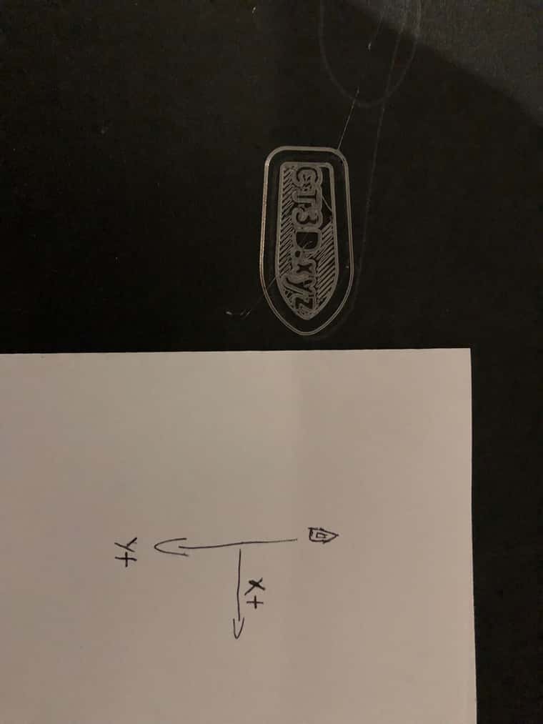
-
I can't tell from your photos how your coordinate system is setup. Can you confirm what droftarts has asked?
X0 Y0 should be with the nozzle/tool at the front left corner of the bed ideally. It can also be in the centre, or the back right, but to start with it's easiest if you set it front left. A positive X move should move the nozzle/tool to the right, and a positive Y move should move the nozzle/tool towards the back of the bed.
-
The tool is positioned at the back left corner of the bed when at X0 Y0. A positive X move shifts the tool to the right, and a positive Y move moves it toward the front of the bed.
L'outil est positionné dans le coin arrière gauche du plateau lorsque les coordonnées sont à X0 Y0. Un mouvement positif en X déplace l'outil vers la droite, et un mouvement positif en Y le déplace vers l'avant du plateau.
-
@404-print said in Mirror printing issue:
The tool is positioned at the back left corner of the bed when at X0 Y0. A positive X move shifts the tool to the right, and a positive Y move moves it toward the front of the bed.
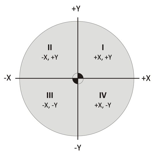
That’s why your prints are mirrored. X0 Y0 should be FRONT left corner. Think of it as looking at the printer from above; like a graph, the origin would be bottom (ie front) left.
See my advice earlier for changing this.
The “right hand coordinate system” is long established in the CNC world. See https://www.autodesk.com/products/fusion-360/blog/cnc-coordinate-system-made-easy/
There’s no option to change the coordinate system from right hand to left hand in firmware.
Ian
Bed-slinger - Mini5+ WiFi/1LC | RRP Fisher v1 - D2 WiFi | Polargraph - D2 WiFi | TronXY X5S - 6HC/Roto | CNC router - 6HC | Tractus3D T1250 - D2 Eth
-
@droftarts some slicers allow for mirroring the Y axis, and you could use M579 in RRF. To avoid confusion, Id stick with your recommendation of fixing the coordinate system to be the expected setup.
-
Merci à tous, mon problème est résolu.
-
 undefined dc42 marked this topic as a question
-
undefined dc42 has marked this topic as solved