[SOLVED] Help setting up hotend heater
-
Hello. I have a fysect big dipper board (similar to duet3 mini5+) and I'm having trouble getting the nozzle heater to work.
I used the RRF Config Tool website to generate the config.g, but I must have gotten some information wrong.
I've already reviewed each gcode in the configuration but I still can't find where I went wrong. The thermistor is reading the temperature correctly, the hotend fan is working according to the hotend temperature correctly. The problem is that the heater doesn't heat up, it stays OFF all the time, even though I set the temperature via DWC.
Could someone tell me where I went wrong?The heater cartridge is connected to the "V_FUSED+" and "OUT2-" ports in the diagram below. I've also tried configuring it on the "OUT1-" port without touching the wiring, but the result was the same.
I'd appreciate it if anyone could shed some light on this.
Thank you.; General G90 ; absolute coordinates M83 ; relative extruder moves M550 P"Sucata RRF" ; set hostname ; Accessories M918 P2 E-4 F2000000 ; Fysetc 12864mini M950 E1 C"io3.out" T1 U3 ; create a RGB Neopixel LED strip with 3 LEDs on the Duet 3 Mini 5+ 12864_EXP1 header M150 E1 R0 U0 B255 P255 S1 F1 ; display led blue M150 E1 R255 U0 B0 P255 S1 F1 ; left encoder led red M150 E1 R0 U255 B0 P255 S1 F0 ; right encoder led green ; Network M552 S1 ; configure WiFi adapter M586 P0 S1 ; configure HTTP M586 P1 S1 ; configure FTP ; Smart Drivers M569 P0.0 S1 D2 ; driver 0.0 goes forwards (Z axis) M569 P0.1 S1 D2 ; driver 0.1 goes forwards (Z axis) M569 P0.2 S1 D2 ; driver 0.1 goes forwards (Z axis) M569 P0.3 S1 D2 ; driver 0.3 goes forwards (X axis) M569 P0.4 S0 D2 ; driver 0.4 goes forwards (Y axis) M569 P0.5 S1 D2 ; driver 0.2 goes forwards (extruder 0) ; Motor Idle Current Reduction M906 I30 ; set motor current idle factor M84 S30 ; set motor current idle timeout ; Axes M584 X0.3 Y0.4 Z0.0:0.1:0.2 ; set axis mapping M350 X16 Y16 Z16 I1 ; configure microstepping with interpolation M906 X1000 Y1000 Z800 ; set axis driver currents M92 X80 Y80 Z400 ; configure steps per mm M208 X0:269 Y0:259 Z0:300 ; set minimum and maximum axis limits M566 X1800 Y1800 Z12 ; set maximum instantaneous speed changes (mm/min) M203 X12000 Y12000 Z360 ; set maximum speeds (mm/min) M201 X1000 Y1000 Z20 ; set accelerations (mm/s^2) ; Extruders M584 E0.2 ; set extruder mapping M350 E16 I1 ; configure microstepping with interpolation M906 E1000 ; set extruder driver currents M92 E420 ; configure steps per mm M566 E120 ; set maximum instantaneous speed changes (mm/min) M203 E3600 ; set maximum speeds (mm/min) M201 E250 ; set accelerations (mm/s^2) ; Kinematics M669 K1 ; configure CoreXY kinematics ; Probes M558 K0 P9 C"io2.in" H8 F360:120 T6000 R0.5 A5 ; configure BLTouch probe via slot #0 G31 P500 X-21.8 Y3.24 Z0.7 ; set Z probe trigger value, offset and trigger height M950 S0 C"io2.out" ; create servo #0 for BLtouch ; Endstops M574 X2 P"io5.in" S1 ; configure X axis endstop M574 Y1 P"io6.in" S1 ; configure Y axis endstop M574 Z1 S2 ; configure Z axis endstop ; Mesh Bed Compensation M557 X25:175 Y25:175 S40:40 ; define grid for mesh bed compensation ; Sensors M308 S0 P"temp0" Y"thermistor" A"Heated Bed" T100000 B3950 ;B4725 C7.06e-8 ; configure sensor #0 M308 S1 P"temp1" Y"thermistor" A"Nozzle" T100000 B3950 ;B4725 C7.06e-8 ; configure sensor #1 ; Heaters M950 H0 C"out0" T0 ; create heater #0 M143 H0 P0 T0 C0 S110 A0 ; configure heater monitor #0 for heater #0 M307 H0 R2.43 D5.5 E1.35 K0.56 B0 ; configure model of heater #0 M950 H1 C"out1" T1 ; create heater #1 M143 H1 P0 T1 C0 S240 A0 ; configure heater monitor #0 for heater #1 M307 H1 R2.43 D5.5 E1.35 K0.56 B0 ; configure model of heater #1 ; Heated beds M140 P0 H0 ; configure heated bed #0 ; Fans M950 F0 C"out3" ; create fan #0 M106 P0 C"5015Carro" S0 L0 X1 B0.1 ; configure fan #0 M950 F1 C"out4" ; create fan #1 M106 P1 C"Hotend" S0 B0.1 H1 T50 ; configure fan #1 M950 F2 C"out6" ; create fan #2 M106 P2 C"5015Placa" S0 L0 X1 B0.1; configure fan #2 ; Tools M563 P0 D0.5 H1 F1 ; create tool #0 M568 P0 R0 S0 ; set initial tool #0 active and standby temperatures to 0C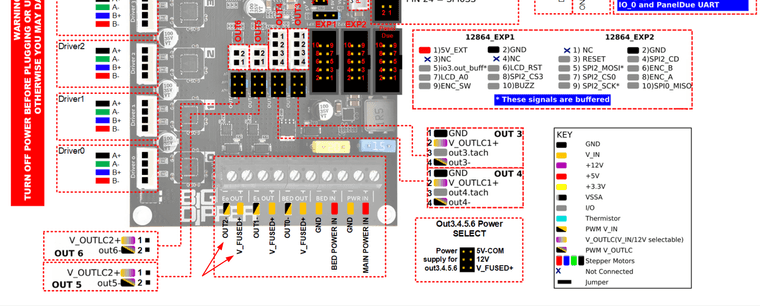
-
@RodrigoRMaraujo Your config.g has "out1" specified for the heater.
M950 H1 C"out1" T1 ; create heater #1If you change the connection to out2, you need to change the M950 line to C"out2".
However, I think your problem is this line:; Tools M563 P0 D0.5 H1 F1 ; create tool #0You have specified the drive number 'D0.5', but the D parameter is the extruder number, not the drive number:
D The 'D' field specifies the drive(s) used by the tool - in the first example drives 0, 2 and 3. The 'D' field number corresponds to the 'E' parameter defined in the M584 command. '0' means first 'E' driver in M584 and so on. Drive 0 is the first drive in the machine after the movement drives (usually X, Y and Z). If there is no 'D' field the tool has no drives.
https://docs.duet3d.com/en/User_manual/Reference/Gcodes#m563-define-or-remove-a-tool
I expect this was causing an error, and either no tool was created, or the tool was created but with no heater. Sending
M98 P"config.g"most likely reports an error in this line. Change it to:; Tools M563 P0 D0 H1 F1 ; create tool #0Ian
-
@RodrigoRMaraujo also add
T0to the end of your config -
@droftarts and @jay_s_uk
Thanks for the answers!
The sum of the 2 suggestions solved my problem.
I think the translation of the documentation into Portuguese by Google made me misspell the D parameter of the M563 command.
I had really forgotten to activate T0.
I used RRF for a few years, since v2.03 and migrated in 2022 to klipper on all machines. Now I'm going back to RRF and I'm trying to remember everything.
Thanks to both of you!