1HCL compatibility question
-
Background: I'm wanting to replace a custom control board with the Duet system, but am not certain I can get the Duet to be accurate enough for the application.
The System: We have what is essentially a custom CNC tubing cutter that is micron accurate. To get that accuracy we have high resolution encoders and an extremely reduced drive on a spindle depth drive, and a tubing feed drive. The tubing feed is spun axially with a third axis using a slip ring for connectivity to the motor/encoder for the feed.
From my reading it seems to be able to read the encoders at all, I'd need a 1HCL board, and set up the Linear quadrature encoder plus Duet3D Magnetic Shaft Encoder on each axis. For 2 of my 3 axis, this isn't really a problem, I have the space and can mount the electronics close enough to not have issue with signal. But for the tubing feed axis, the slip ring only has 8 contacts, and not enough space to change to a 12 contact slip ring. I MIGHT be able to change to a 10 position ring with some trickery.
IF the 1HCL can use 2 SPI encoders, AND I can set them up with only MOSI CLK and CS, then I could reach that 10 position max.
Stepper Coils x4, 5v, Gnd, MOSI, CLK, CS1, CS2.The Questions:
- Can the 1HCL control in this Linear+Shaft encoder setup, an axis with extreme reduction drive? (ie 20k steps/mm reduction)
- Is there a way to use 2 SPI encoders instead of 1 Quadrature, and 1 SPI (magnetic) encoder?
- Can the 1HCL somehow do a Partial Closed Loop without the magnetic encoder for commutation?
- Is there a way to read the encoder ticks directly from the 1HCL without having closed loop setup? (So I can setup a partial closed loop by periodically checking the encoder counts and updating the movement commands)
Thanks
-
@ironhydroxide is there room for you to mount the 1HCL so that it moves with the motor? then you would only need 4 slip rings for power and CAN.
-
@dc42 That's a great Idea, that I didn't even consider.
But Sadly that won't work for me.
If the PCB were 1/2 the size in all dimensions then it'd be a maybe.
-
@dc42 Thinking about it. For this setup the perfect board would be one that fits on the back of a NEMA17 stepper, with mag encoder built on board, and 4 connectors broken out the side of the board. 4pin stepper power, 4pin quadrature encoder, 2pin power, 2pin can.
It's a pretty niche setup, but it's possible others might be interested in such a stripped down Closed Loop board. (if such would even be possible)
-
@ironhydroxide we've considered this in the past and I'll take another look at it. To keep costs reasonable we'd probably need to specify a maximum VIN voltage of 36V rather than 48V. Would that be OK for you?
-
@ironhydroxide @dc42
I just did this. Just for my pnp set up to get ride of the MKS Servo42D. Basically 1HCL + mag board wo any io
-
@dc42 I believe it would. Current controller is on ancient stepper drivers at ~38vdc, I can't see newer drivers at slightly lower voltage being any worse, and likely better.
-
@wayneosdias
If that is what I think, it looks very much like what I'm looking for.
Have you already made these boards? how tall are the components on them? (I have minimal back clearance, would like to not have to go to a shorter motor if possible) -
@ironhydroxide Hey Iron, This will be a Nema17 mounted Duet 1HCL + Duet Magnet board without any gpio. Im keeping all the original 1HCL Duet peripheral pin assignments, just not using all of them to speed up the process.
This will be my 2nd Custom Duet Expansion. The First go around I added accelerometer, 2 addl drivers and messed around w the pin assignments. It all works great but took a couple weeks to get right. I think the above should work as intended much quicker by not going off script with pin/peripheral assignments. I just don't have time to keep the machine down, I use it for production.
I always order a couple boards. Once I get one built and confirm fxn I can send you a spare pcb if your in the states. In keeping w Duet opensource Ill make all dev files available if you feel like using the design on some level. Keep in mind some of my apparently odd part choices are based on what I have on hand, like the full reel of dual channel Vregs my company is not going to use...
-
@wayneosdias that sounds like it would work for me very well.
My only hesitation on it, as said before, is the thickness of the populated board.Part of that I can mitigate by soldering connector leads to the board, and having the connectors next to the motor instead of directly behind it, but if you use the same capacitors as the 1HCL, that kinda makes it difficult. those are pretty tall.
It also looks like you're only going 24v and 3.3v?
Is there any chance of there being space for a 5v regulator and some (pie in the sky) selector solder pads with resistor divider for the Encoder power/input?Please don't take this as criticism. I appreciate greatly your willingness to share this board, and would gladly test it with my setup.
If I can get this proof of concept working/approved, and you're interested, my company is likely to be needing 250-300 of them to retrofit all of our current equipment.
-
@ironhydroxide
Hi Iron,Interesting offer, but I simply don't have the bandwidth to take on such a project or attempt to support it. With the qty you're looking at, Duet and or possibly a sub-contractor would be your best bet. That said, sounds like your design criteria would be fairly easy to meet, but one off propriety in nature. You need to get a design engineering quote, maybe the folks at Duet could point you in the right direction.
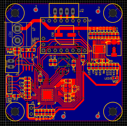
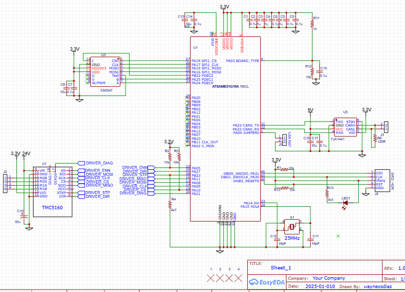
That said I'm just throwing my design out there to share w the community. I didn't put out the full schematic, heres the supply side of things, 24V 5V 3v3. Fyi the pic of the pcb i posted above was a first pass I did in a couple of hrs. Im sure its going to change after some more DRC checks. Ill prolly order the board Monday. Its simply to illustrate the Duet control accessory scheme is flexible enough to meet what it is you're proposing, even with some of your physical design constraints.
I am editing this post by removing the V supply schematic. The schematic was pulled from a different design and not fully reviewed for use in this case. Upon review the circuit needs to be reworked and not acceptable as initially posted.
-
@wayneosdias Completely understand on not having the desire to take a custom project on.
I'm glad there are people like you who are willing to help out, and also give their designs out for the community.I'll look more into the Duet solution and hope that something can come of that. At the moment i'm in the proof of concept phase. but it's looking very hopeful, Duet is a lot more flexible than I imagined before looking into it in earnest.
-
Well it's really a testament to David, Duet and the Moderators. I wouldn't even know where to start without them. Mechatronics isn't my thing even though I rely on 4 one-off purpose-built machines for my business. I can just scheme general design concepts and leverage the Duet system to meet the control needs.
-
@ironhydroxide @wayneosdias this sort of board has been on the hardware roadmap for me for a while.
What clearance do you have at the back of your motors @ironhydroxide ?
-
@T3P3Tony With the current motor/mount I have ~1.5mm clearance from the back of the motor to the nearest obstruction, With a modified mount I can get that to ~5mm. I'm 99% certain that is too close, especially when the magnet for the current board is 4mm thick. (shaft not recessed).
I am looking at options for shorter motors, but I'm already at a 19mm motor, so options are scarce.With some redesign of parts (and added machining I'm hoping to avoid) I can probably get 7mm max clearance with the current motor. Again, not very much room.
Edit. Found a motor that's only 12mm long that "should" work for this (of course have to test). This would give me 9-12mm clearance at the back of the motor (9mm with my current motor mount, up to 12mm with modified motor mount.)
-
@ironhydroxide you may be able to get versions of the motor with a recessed shaft to (say) 3.5mm which might just allow you to fit a magnetic encoder board with a different header from our standard on into the gap. Then mount a board on one of the motor sides rather than on the back for the closed loop control. Let me know once you have explored the options for creating clearance on the back.
-
@T3P3Tony said in 1HCL compatibility question:
Then mount a board on one of the motor sides rather than on the back for the closed loop control
Good call on the recessed shaft, I'll look into them.
I also found some diametrically opposed magnets on McMaster that are only 1.6mm tall (up to 12.7mm diameter) so that could help with clearance as well.
Sadly the back of the motor is the most feasible location without a complete redesign/machining of the rotation system.
the max swing radius is 30mm, giving me at most 60mm(really only ~50 usable). as the motors are ~42mm that leaves ~8mm for mounting, electronics, wiring, etc.I think I'll pick up one of those 12mm long motors, and a larger diameter but shorter magnet, and do a static test, see what clearance the encoder chip can deal with, with larger diameter but thinner magnets. That will at least get me an idea of remaining space (and if that motor can drive the feed system)
-
@wayneosdias I took a look at your schematic. The TMC5160 needs external mosfets to drive the stepper motors. For small motors the TMC2240 would be better, if you don't mind the max VIN voltage being about 36V.
-
@ironhydroxide check the max temperature the motor will get to and look at the specs of the magnets. We use high temperature magnets for mounting on the motor shaft (which is not needed in many cases but could help if running hot). A slightly wider diameter magnet will work slightly better for the same flux density, up to about 10mm see this figure from the AMS application note:
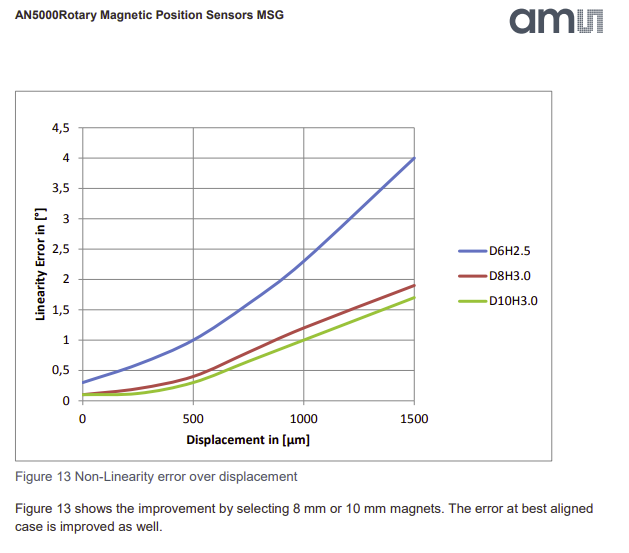
We chose a 6mm magnet because that fits even in recessed shaft NEMA 17 motors
-
@T3P3Tony Good call, I didn't think about heat. The current motors never get above 40c, a thinner might get hotter due to the same energy in a smaller package (or less efficient), will have to test.
Magnets are all rated to 54c and 80c depending on diameter so I think/hope I'll be fine there.for the widest use case, the 6mm makes perfect sense.
I'm just on the far end of the curve, so I get(have) to look at all options, and if a 10mm magnet is more accurate that can't hurt if it also gives more space to work with.