Duet3D Logo Duet3D
    • Tags
    • Documentation
    • Order
    • Register
    • Login

    Custom toolboard + duet wiring limitations

    Scheduled Pinned Locked Moved
    Duet Hardware and wiring
    6
    24
    400
    Loading More Posts
    • Oldest to Newest
    • Newest to Oldest
    • Most Votes
    Reply
    • Reply as topic
    Log in to reply
    This topic has been deleted. Only users with topic management privileges can see it.
    • fcwiltundefined
      fcwilt @SamKudarauskas
      last edited by

      @SamKudarauskas

      Have you determined how many conductors your ribbon cable will need to be equivalent to the individual wires, taking into account the various different wire gauges that would likely be in use?

      For example I run 18 gauge wire to carry the load of the heaters and fans which works out to about 16 conductors in common ribbon cable with 24 gauge conductors.

      Is your tool swapping device something like these?

      Hermit Crab

      Mutant

      Frederick

      Printers: a E3D MS/TC setup and a RatRig Hybrid. Using Duet 3 hardware running 3.4.6

      SamKudarauskasundefined 1 Reply Last reply Reply Quote 0
      • SamKudarauskasundefined
        SamKudarauskas @fcwilt
        last edited by

        @fcwilt Mine is similar. However it rather than an electrical connection between the master plate and the tool plate mine is purely mechanical and I plan to just unplug the single ribbon cable from my PCB when I switch tools. Yes, I have taken into account the necessary wire gauges for the heaters.

        Sam

        jay_s_ukundefined 1 Reply Last reply Reply Quote 1
        • jay_s_ukundefined
          jay_s_uk @SamKudarauskas
          last edited by

          @SamKudarauskas everything switches on the negative side

          Owns various duet boards and is the main wiki maintainer for the Teamgloomy LPC/STM32 port of RRF. Assume I'm running whatever the latest beta/stable build is

          SamKudarauskasundefined 1 Reply Last reply Reply Quote 0
          • SamKudarauskasundefined
            SamKudarauskas @jay_s_uk
            last edited by

            @jay_s_uk So am I safe to connect everything that uses +24V together (hot end heater and two fans) and then just run each individual ground wire back? Is this unadvisable for any/all of the components I wish to connect to my board? Also does the thermistor run on +3.3V and can its +V wire be combined with that of my force sensitive resistor that uses an io port?

            Thank you for your help - Sam

            jay_s_ukundefined 1 Reply Last reply Reply Quote 0
            • jay_s_ukundefined
              jay_s_uk @SamKudarauskas
              last edited by

              @SamKudarauskas nothing wrong with you bunching all the 24v together with individual grounds back.
              The thermistor uses VSSA so it would have to have its own wiring
              you may have difficulties with an accelerometer as it uses SPI to connect and being combined with all the other cabling you may have interference issues

              Owns various duet boards and is the main wiki maintainer for the Teamgloomy LPC/STM32 port of RRF. Assume I'm running whatever the latest beta/stable build is

              SamKudarauskasundefined 1 Reply Last reply Reply Quote 0
              • SamKudarauskasundefined
                SamKudarauskas @jay_s_uk
                last edited by

                @jay_s_uk Ok thank you for your help. Is using out1's 24V line the best place to draw the 24V from to power everything? Also, would using a separate ribbon cable be best for the accelerometer or would that still have interference problems if that ribbon cable is in the same wiring loom as the main ribbon cable?

                jay_s_ukundefined 1 Reply Last reply Reply Quote 0
                • jay_s_ukundefined
                  jay_s_uk @SamKudarauskas
                  last edited by

                  @SamKudarauskas I would just take the power directly from the PSU and then make sure you don't exceed the mosfets switching capability for each out connection you're going to use to switch load.
                  and a separate cable would be a better idea. I've been able to run an accelerometer with a 2.7m USB3 cable. you may get away with a ribbon cable

                  Owns various duet boards and is the main wiki maintainer for the Teamgloomy LPC/STM32 port of RRF. Assume I'm running whatever the latest beta/stable build is

                  SamKudarauskasundefined 1 Reply Last reply Reply Quote 0
                  • SamKudarauskasundefined
                    SamKudarauskas @jay_s_uk
                    last edited by SamKudarauskas

                    @jay_s_uk Why is taking the +24V from a main line rather than from the dedicated +24V pin for each component run the risk of blowing the mosfet? What is the current limit on the mosfets and is my wire simplification idea worth it if I run the risk of damaging the board? What kind of precautions could I take to just use the +24V from heater 1?

                    Also, I probably should have mentioned this earlier but I was inspired by this:d1fff08d-df40-4b34-b015-67dd643a6564-image.png

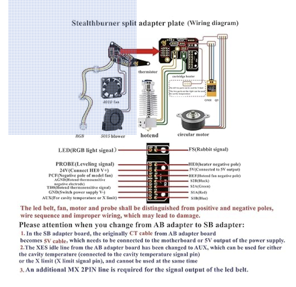
                    Edit: link to part here

                    On this stealthburner part it appears that they hae done some sort of wire simplification since it looks like they have more things connected to the board then wires running back to the main baord and I wanted to do something similar.

                    Edit: The stealthburner part has pins labeled +24V (connected to heater 0 V+), +5V and GND which appear to have multiple things connected to it. Hence where my idea to simply the wiring came from.

                    1 Reply Last reply Reply Quote 0
                    • SamKudarauskasundefined
                      SamKudarauskas
                      last edited by

                      What is the mosfet switching capacity of the fan GND pins? Is it rated to handle the current that heater 1 outputs? If it is, would that be the simpliest way to simplify the wires and feed +24V to heater 1 and both of my fans?

                      jay_s_ukundefined 1 Reply Last reply Reply Quote 0
                      • jay_s_ukundefined
                        jay_s_uk @SamKudarauskas
                        last edited by

                        @SamKudarauskas i meant to reply to you before.
                        The heater outputs on a mini 5+ can handle 5A switching loads each (out 1 and out 2) and the rest of the outs (out 3 - out 6) can handle 2A switching loads per output, all at 24V.
                        So as long as whatever you're switching (heater or fan etc) is less than those values each you'll be fine.
                        If you take the supply from out1, the maximum onboard 24v output current is 10A, that includes steppers etc which is why toolboards etc are usually wired directly to the PSU with their own fuse.
                        Are you looking to replicate the stealthburner setup?

                        Typically running lots of wires like the stealthburner setup you linked to was only done because some people were cheap and they couldn't afford a CAN toolboard or because some people are against CAN in the klipper world.
                        But when you typically find, unless you're running proper cable aimed at continually being moved and conform to t he correct bend radius of stuff, one of the cables will break. You constantly hear voron users with the stock setup complaining of a cable being broken preventing something from working.

                        So my advise would be to avoid this sort of setup, especially if you're running a mutlicore cable to the print head.
                        Is there any particular reason you're against using a CAN toolboard?
                        What type of toolhead setup is it?

                        Owns various duet boards and is the main wiki maintainer for the Teamgloomy LPC/STM32 port of RRF. Assume I'm running whatever the latest beta/stable build is

                        SamKudarauskasundefined 1 Reply Last reply Reply Quote 0
                        • SamKudarauskasundefined
                          SamKudarauskas @jay_s_uk
                          last edited by

                          @jay_s_uk Thank you for your reply. Do I understand this correctly? As long as each fan draws less than the 2A switching load max then it doesn't matter where the +24V comes from, so I can use out1 to power the heater and the two fans.

                          I'm not looking to directly replicate the stealth burner setup. I like to build different toolheads for my custom built 3D printer which is why I built a tool hot swap setup. My printer is small and my duet has many available pins on it so I'd rather just use the capabilities of my mainboard then spend $45+ dollars on a Duet tool board for each new tool I build.

                          My idea has all of the convivences of a CAN tool board without the extra cost. My Prusa Mk4S with the Prusa Loveboard has a very similar setup to my idea for the same reasons and I wanted to implement it in the printer that I built. By making it myself it can be much more compact since it doesn't need any driver chips on it as well. Also truthfully, its a fun project for me to learn KiCAD.

                          jay_s_ukundefined 1 Reply Last reply Reply Quote 0
                          • jay_s_ukundefined
                            jay_s_uk @SamKudarauskas
                            last edited by

                            @SamKudarauskas fair enough.
                            and yes, you understand that correctly

                            Owns various duet boards and is the main wiki maintainer for the Teamgloomy LPC/STM32 port of RRF. Assume I'm running whatever the latest beta/stable build is

                            SamKudarauskasundefined 1 Reply Last reply Reply Quote 0
                            • SamKudarauskasundefined
                              SamKudarauskas @jay_s_uk
                              last edited by

                              @jay_s_uk Thank you for your help. Is the duet IO pins capable of triggering different events if it receives a pulse of being turned on/off versus a stable on or off signal?

                              jay_s_ukundefined 1 Reply Last reply Reply Quote 0
                              • jay_s_ukundefined
                                jay_s_uk @SamKudarauskas
                                last edited by

                                @SamKudarauskas yes. have a look at M581

                                Owns various duet boards and is the main wiki maintainer for the Teamgloomy LPC/STM32 port of RRF. Assume I'm running whatever the latest beta/stable build is

                                SamKudarauskasundefined 1 Reply Last reply Reply Quote 0
                                • SamKudarauskasundefined
                                  SamKudarauskas @jay_s_uk
                                  last edited by

                                  @jay_s_uk M581 appears to be used to detect going from low to high or high to low for some trigger, how can I use that to map it to different actions based off of if it goes high low high quickly or just from low to high and stays that way?

                                  fcwiltundefined gloomyandyundefined droftartsundefined 3 Replies Last reply Reply Quote 0
                                  • fcwiltundefined
                                    fcwilt @SamKudarauskas
                                    last edited by fcwilt

                                    @SamKudarauskas

                                    I'm using a Duet 3 6HC board with 3.5.4 firmware.

                                    I have cases where I have used M581 to assign two triggers to the same input.

                                    One for the inactive-to-active condition and the other active-to-inactive condition.

                                    It seems to work just fine.

                                    But I'm not sure how you would detect a steady state condition.

                                    Frederick

                                    Printers: a E3D MS/TC setup and a RatRig Hybrid. Using Duet 3 hardware running 3.4.6

                                    SamKudarauskasundefined 1 Reply Last reply Reply Quote 0
                                    • gloomyandyundefined
                                      gloomyandy @SamKudarauskas
                                      last edited by

                                      @SamKudarauskas It might help if you explain what it is you are trying to do here. So what sensor (or other input) are you trying to monitor and what conditions do you want to detect and what do you want to do when that condition is detected.

                                      1 Reply Last reply Reply Quote 0
                                      • droftartsundefined
                                        droftarts administrators @SamKudarauskas
                                        last edited by

                                        @SamKudarauskas you can use M582 https://docs.duet3d.com/User_manual/Reference/Gcodes#m582-check-external-trigger to check the state of a trigger, and to trigger it if it is in a particular state.

                                        Ian

                                        Bed-slinger - Mini5+ WiFi/1LC | RRP Fisher v1 - D2 WiFi | Polargraph - D2 WiFi | TronXY X5S - 6HC/Roto | CNC router - 6HC | Tractus3D T1250 - D2 Eth

                                        1 Reply Last reply Reply Quote 0
                                        • SamKudarauskasundefined
                                          SamKudarauskas @fcwilt
                                          last edited by SamKudarauskas

                                          @fcwilt I was curious about binding two or more macros to a single button. One to execute if the button is tapped and a different one if it is held down.

                                          Sam

                                          fcwiltundefined T3P3Tonyundefined 2 Replies Last reply Reply Quote 0
                                          • fcwiltundefined
                                            fcwilt @SamKudarauskas
                                            last edited by

                                            @SamKudarauskas said in Custom toolboard + duet wiring limitations:

                                            @fcwilt I was curious about binding two or more macros to a single button. One to execute if the button is tapped and a different one if it is held down.

                                            Sam

                                            Held down how long?

                                            You might be able to put in the trigger a G4 delay followed by a test of the appropriate input using

                                            sensors.gpIn[#].value = 0 
                                            ; or
                                            sensors.gpIn[#].value = 1
                                            

                                            where # is the number of the gpin used as the input for the trigger to monitor.

                                            Frederick

                                            Printers: a E3D MS/TC setup and a RatRig Hybrid. Using Duet 3 hardware running 3.4.6

                                            1 Reply Last reply Reply Quote 0
                                            • First post
                                              Last post
                                            Unless otherwise noted, all forum content is licensed under CC-BY-SA