Duet & Reprap firmware is destroying my CR10s Z stepper motors
-
Could anybody point me towards any documentation on how to configure the Duet for a CR10s? Apparently there may be a wiki somewhere for reprap firmware config for tuning specific printers
The dual z axis motors seem to be out of phase and are making a terrible grinding noise when moving up or down the Z axis.
I'm using the default settings from the reprap configuration tool and i'm wondering if the current is too low set to 800mA
but I keep seeing log warnings
G28 Z Warning: VIN under-voltage event (9.4V)
when the motors are rated 3-5v and my power supply is tuned to 13.7V
-
correction I believe that the voltage on the CR10s VREF is about 0.9-1V for Dual Z in series.
I should also say that X and Y stepper motors sound fine.
I have measured the X Axis bar holding the hot end is perfectly level to the bed.
-
Hi.
Could you please post your config.g file? Have you verified that the stepper motors are not out of phase? Do the motors move and make a grinding noise, or do they not move at all?
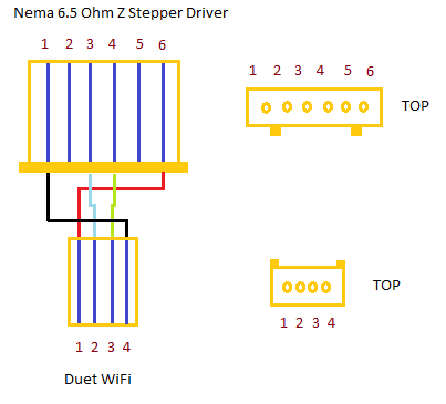
If you want to verify the phases, the best way is with a multimeter. You are looking for two pairs of wires that don't read open circuit (OL) when you touch the meter pins to the stepper wires.
https://d17kynu4zpq5hy.cloudfront.net/igi/duet3d/bhoDb6XUVYW4uPLG.huge
As you see in the wiring diagram the pinout is
Phase 1A (pair one)
Phase 1B (pair one)
Phase 2A (pair two)
Phase 2B (pair two) -
@qdeathstar said in Duet & Reprap firmware is destroying my CR10s Z stepper motors:
)
Most of the weight is just on one of the z axis stepper motors where the x axis stepper motor is mounted on the x axis hot end cross bar. The Z axis does moves in correct direction ... but it looks like the loaded stepper motor is struggling to keep up with the other less loaded stepper motor on the other side because its lacking power/torque.
This was working fine on the Melzi board I have just swapped out.
I cant upload a 1.3MB Video on this forum but you can view it here
https://www.simonfoley.net/stepper.mp4To me this looks like a torque/power issue and I need to be able to increase the voltage to approx 1v.
The reprap firmware confuses me when it suggests it limits current as typically voltage is the driver for the current and the stepper motor will pull what current it can based on its impedance and available voltage. I have never used TMC Drivers before.
0_1523577191075_config.g [0_1523578342474_20180413_020549_1.mp4](Uploading 100%)
-
The steps per mm on your z axis looks pretty high at 4000. Is that correct?
What is the rated max current of the z axis motors? Setting them about 80-85% of rated is a good place to start.
-
I think he might have added one too many zeros.
-
@simonboydfoley said in Duet & Reprap firmware is destroying my CR10s Z stepper motors:
Could anybody point me towards any documentation on how to configure the Duet for a CR10s? Apparently there may be a wiki somewhere for reprap firmware config for tuning specific printers
The dual z axis motors seem to be out of phase and are making a terrible grinding noise when moving up or down the Z axis.
I'm using the default settings from the reprap configuration tool and i'm wondering if the current is too low set to 800mA
but I keep seeing log warnings
G28 Z Warning: VIN under-voltage event (9.4V)
when the motors are rated 3-5v and my power supply is tuned to 13.7V
If under voltage events occur when you try moving motors, that indicates a power problem. Check that the VIN terminal block screws are tight.
-
@number40fan said in Duet & Reprap firmware is destroying my CR10s Z stepper motors:
I think he might have added one too many zeros.
I would tend to agree I think that 4000 would be for M8 Threaded rods but AFAIK the CR10 uses TR8x8 leadscrews which if my calls are correct 200(steps per Rev) x 16 (Microstep rate) = 3200 microsteps per rev but 1 rev of the motor will move the gantry 8 mm so 3200/8 = 400 steps/mm.
If someone would confirm my figures it would maybe sort out the issue.
Doug
-
I experienced a similar problem when I swapped from RAMPS to my Duet WiFi. RAMPS runs the motors in parallel, Duet wires them in series. With a 12-volt system, series wiring greatly decreases the torque available unless the current limit is raised. I tried increasing the current to the point where the motors got rather warm, but I still experienced missed steps.
I mostly solved my issues by mapping an unused driver (EX1) to run the other Z motor. In the process, I still occasionally experienced binding. Ultimately, I discovered that the threaded rods that I was using for my Z leadscrews were not aligned properly and had worn to the point where the threads were galled. Swapping to TR8X2 leadscrews helped immensely, though the brass nuts leave a bit to be desired, even when lubricated. Delrin nuts are on order.
-
Thanks for the help everybody ... its given me some pointers on next steps to investigate.
FYI Those figures I got from the Reprap online Configuration Tool ... see attached ... I thought they looked a bit suspect hence my search for some documentation. If I fix it ... I will post the solution.
-

-
@simonboydfoley You need to click on the link at the top right of that image to calculate steps per mm. It pops up a little window where you can enter the details of your system and it will give you the correct steps per mm to use.
-
Thanks for that spot @Phaedrux I didn't notice that doh!
I went back and copied my settings from Marlin to the duet .
I also checked out the wiring and it all buzzed out correctly.
The Stepper motors have coils rated at 6.5 Ohms.The problem still exists. However checking other CR10 Users who have upgraded to the Duet they have also used the spare Extruder 4 driver for the second Z Stepper motor ! and then using a M584 to map them to the Z Axis
This is a little worrying and would but a total fail for the Duet card if it cant manage a simple dual z axis setup.
I've never calibrated stepper motors before so I'm still researching to find out what the problem is (phase issues / voltage / current).
The current setting in reprap on the drivers is confusing but I understand that the duet calculates the resistance and then adjusts the voltage to achieve the desired current.
-
Not sure what caused the problem but I tested and then reconnected everything and reduced the current to 700mA and found this setting
M671
; Drives
M569 P0 S1 ; Drive 0 goes forwards
M569 P1 S0 ; Drive 1 goes forwards
M569 P2 S0 ; Drive 2 goes forwards
M569 P3 S1 ; Drive 3 goes forwards
M350 X16 Y16 Z16 E16 I1 ; Configure microstepping with interpolation
M92 X80 Y80 Z399.29 E95 ; Set steps per mm
M566 X900 Y900 Z24 E300 ; Set maximum instantaneous speed changes (mm/min)
M203 X3000 Y3000 Z1000 E3000 ; Set maximum speeds (mm/min)
M201 X1800 Y1800 Z20 E5000 ; Set accelerations (mm/s^2)
M906 X700 Y700 Z700 E700 I30 ; Set motor currents (mA) and motor idle factor in per cent
M84 S30 ; Set idle timeout; Axis Limits
M208 X0 Y0 Z-1.32 S1 ; Set axis minima
M208 X300 Y285 Z400 S0 ; Set axis maxima; Lead Screw Offsets
M671 X-20.0:325.0 Y100.0:100.0 ; leadscrew offsets from home -
Problem Solved:
It was the current / voltage that was set too high by the reprap firmware configurator
Set current from 800 to 700 and the problem was solved.
I got this fix from a fellow CR10 to Duet converter;
For fellow CR10S users these are the Marlin settings for the stock stepper motors;
X Axis Motor: (4.5 Ohms) A= 525 mA
y Axis Motor: (4.5 Ohms) A= 600 mA
z Axis Motor: (6.5 Ohms) A= 675 mA
e Extruder Motor: (4.5 Ohms) A=600mASteps per mm:
x = 80
y = 80
z = 400
e = 95Max Feed Rate:
x = 2500
y = 2500
z = 100
e = 25Max Acceleration:
x = 3000
y = 3000
z = 100
e = 10000Micro Step:
x = 16
y = 16
z = 16
e = 16Default Jerk:
x = 10
y = 10
z = 0.3
e = 5Default Acceleration = 575
Default Retraction Acceleration = 1000
Default Travel Acceleration = 1000Note: RepRap descriptive language for Endstop location is really confusing for Marlin users ....
"High Location" and "Low Location" does not refer to where the endstop is located relative to the 0,0 origin ..... it refers to where the "Nozzle Head" will be when the end stop is triggered regardless of where it is located. So for CR10 Users all end stops are "Low Location" even though the Y axis end stop is located at 300 end of the bed (this wasted days of troubleshooting!)
; Endstops
M574 X1 Y1 Z1 S1 ; Set active high endstops -
When using high inductance low current motors like the ones on your CR10, the two Z motors should either be connected to separate driver outputs, or connected in parallel to just one of the Z driver outputs with jumpers fitted in the second Z driver output.
Connecting the two Z motors in series, which is how the two Z motor connectors are wired on the Duet, works better for the low inductance higher current motors that are more commonly used in 3D printers.
Duet WiFi hardware designer and firmware engineer
Please do not ask me for Duet support via PM or email, use the forum
http://www.escher3d.com, https://miscsolutions.wordpress.com -
@simonboydfoley "Active" high and "Active" low refer to how the switch is wired. An "active high" end stop is a switch that is normally closed and opens when it is triggered. This is considered "safer" since if a switch wire were to disconnect or switch were to fail it would in theory open the circuit and cause the switch to trigger. This prevents you from finding out your endstop switch isn't connected as your carriage slams into the side, or the nozzle crashes into the bed.
In terms of location, my Y end stop is at the 300 end of my bed too. I have my Y end stop configured as a "high end" location. My nozzle position after homing is (0, 300), so I am not sure what you meant there. One thing that did trip me up is that even if you re-configure the location of the end stop (say using the configurator) you have to edit (or replace) your home.g and homeall.g to tell the printer to home towards the high end for Y. I didn't do this at first and ended up being very confused as for a short while as well.
-
Thanks for taking the time to reply. I attach a diagram to explain the gotcha on RepRapFirmware setup for homing on a CR1O in case it helps other people converting from Marlin to RepRapFirmware;
This is the only way I could get it working. I have made an assumption here that RepRap does not have a dependency on the physical wiring direction of the motor and that you can override this by setting the stepper motor direction. I tried reversing the direction of my stepper motor (M569 P1 S0) and setting the Y stepper motor to High Location ....(Y2) which is logical ... but it would not work and tried to home the printer at (0,300) not (0,0).
So I deduce that Low Location and High Location does not refer to where the End Stop is located ... but where the Nozzle will be when the end stop is triggered.

-
@dc42 Thanks for this information. Very helpful.
When I looked at the Duet specs I was content that both the Duet and the Melzi wire the Z Stepper motors in series ... So I did not think there would be an issue because I did not know stepper motors would be that different on a CR10 compared to other printer.It then confused me why people were not using the second series Z Stepper driver port on the card and using E1 Extruder driver instead.
What would be better .... move Z2 to E1 or buy 2 low inductance Z stepper motors ?
-
Yes the low end/high end refers to where the nozzle is when the endstop switch is triggered.
If the E1 output is free than I suggest you connect the second stepper motor to E1, to avoid having to buy new motors. Then put M584 X0 Y1 Z2:4 E3 in config.g, before any M350 or M906 commands.