Duet3D Logo Duet3D
    • Tags
    • Documentation
    • Order
    • Register
    • Login
    1. Home
    2. simonboydfoley
    • Profile
    • Following 0
    • Followers 0
    • Topics 9
    • Posts 38
    • Best 1
    • Controversial 0
    • Groups 0

    simonboydfoley

    @simonboydfoley

    1
    Reputation
    1
    Profile views
    38
    Posts
    0
    Followers
    0
    Following
    Joined Last Online

    simonboydfoley Unfollow Follow

    Best posts made by simonboydfoley

    • RE: Duet & Reprap firmware is destroying my CR10s Z stepper motors

      Problem Solved:

      It was the current / voltage that was set too high by the reprap firmware configurator

      Set current from 800 to 700 and the problem was solved.

      I got this fix from a fellow CR10 to Duet converter;

      For fellow CR10S users these are the Marlin settings for the stock stepper motors;

      X Axis Motor: (4.5 Ohms) A= 525 mA
      y Axis Motor: (4.5 Ohms) A= 600 mA
      z Axis Motor: (6.5 Ohms) A= 675 mA
      e Extruder Motor: (4.5 Ohms) A=600mA

      Steps per mm:
      x = 80
      y = 80
      z = 400
      e = 95

      Max Feed Rate:
      x = 2500
      y = 2500
      z = 100
      e = 25

      Max Acceleration:
      x = 3000
      y = 3000
      z = 100
      e = 10000

      Micro Step:
      x = 16
      y = 16
      z = 16
      e = 16

      Default Jerk:
      x = 10
      y = 10
      z = 0.3
      e = 5

      Default Acceleration = 575
      Default Retraction Acceleration = 1000
      Default Travel Acceleration = 1000

      Note: RepRap descriptive language for Endstop location is really confusing for Marlin users ....

      "High Location" and "Low Location" does not refer to where the endstop is located relative to the 0,0 origin ..... it refers to where the "Nozzle Head" will be when the end stop is triggered regardless of where it is located. So for CR10 Users all end stops are "Low Location" even though the Y axis end stop is located at 300 end of the bed (this wasted days of troubleshooting!)

      ; Endstops
      M574 X1 Y1 Z1 S1 ; Set active high endstops

      posted in Duet Hardware and wiring
      simonboydfoleyundefined
      simonboydfoley

    Latest posts made by simonboydfoley

    • RE: Blinking bltouch

      I get this a lot with my BL Touch. Its always been been the connectors (I use latched Dupont connectors at the hot end side). You could just cut off the connectors and solder a wire all the way back to the duet to eliminate them. What I found worked very well was a 3 x 2 standard block Dupont Connector (not latched) that I used to connect the 3 logic pins to the 50Pin Male connector on the Duet Wifi board (Orange Brown and yellow). It will be these three pins that will be causing the problem.
      If you have used the connectors at the hot end side ... the cable they provide is very thin (shit actually) and hard to crimp reliably. I soldered and heat shrinked some solid core wire and used that wire to crimp pins for the connector. It mostly fixed my issue.

      FYI Continuity testing dose not always pick up the issue if is a broken pin barb on the connector it can get pushed back in the housing if that's broken and you don't spot that when you continuity test further up the pin on the exposed bit where the barb latches. What happens is that when connecting male to female the broken pin gets pushed back and makes a very poor contact.

      Good luck this drives me nuts too.

      posted in General Discussion
      simonboydfoleyundefined
      simonboydfoley
    • RE: Duet Bed Mesh Compensation incorrectly showing Z Offset ?

      hi @Phaedrux , Thanks for the reply
      to answer your questions, No I will read it now .... not sure it existed at the time I bought my Duet. I'll see if I have done something dumb.

      [Edit: The only thing I have spotted that I don't do is cancel previous mesh bed levelling before I set the Z=0 and offset procedures, cant see that being relevant as the G92 z0 when the nozzle is on the bed sets the golden reference point ]
      ... I attach requested files

      homeall.g
      homedelta.g
      homex.g
      homey.g
      homez.g
      heightmap.csv
      config.g

      posted in Tuning and tweaking
      simonboydfoleyundefined
      simonboydfoley
    • Duet Bed Mesh Compensation incorrectly showing Z Offset ?

      Hi All,
      I have a BLTouch Z Probe with my Duet2Wifi for my CR10s printer.
      I upgraded to the latest firmware, web server etc and I now get the following error when ever I do a mesh bed compensation;

      G29
      Warning: the height map has a substantial Z offset. Suggest use Z-probe to establish Z=0 datum, then re-probe the mesh.
      49 points probed, min error -1.482, max error -1.175, mean -1.340, deviation 0.077

      This is the procedure I normally follow.

      (With Z offset set 0 G31 X-40 Y-10 Z0 P25 I1).

      1. Home all axis.
      2. disable axis limits. (M564 S0, G1 Z0)
      3. level the nozzle to the bed and set actual Z (G92 Z0)
      4. Work out the actual Z offset needed for the probe (G1 Z10,G30 S-1) x 5
      5. work out the average offset and then set the offset in config.g
        G31 X-40 Y-10 Z*** P25 I1 where *** = my calculated offset (positive decimal)
        6). restart the Duet.
        7). home and center.
        8). Run Bed mesh compensation

      I get the following graph from the Duet and the error message!
      MeshCompAfterOffset.jpg

      So it shows the bed as being "below Z=0"

      so it looks like the duet is mistakenly applying the offset twice ??!?

      It dose not seem to be affecting the print so it could just be an error in the software ?

      If I do a mesh compensation after setting the Z to the actual Bed I get a more reasonable result ....

      MeshCompBeforeOffset.jpg

      posted in Tuning and tweaking
      simonboydfoleyundefined
      simonboydfoley
    • RE: Strange Behaviour from DuetWiFi Extruder Stepper [Solved]

      @bearer yup I am sure the wiring is correct .... I spent a lot of pain learning that the Stepper Motors that Creality use on the Extruder are different to the ones they use on the X, Y & Z axis ...
      (Looking down on the Extruder Motor);

      1. Black
      2. Blue
      3. Green
      4. Red

      & Reverse the direction in config
      Or

      1. Red
      2. Green
      3. Blue
      4. Black

      Maybe this is the norm for most Motors ... I have only even used a CR10s.

      Thanks for the tip ... I have ordered a new crimp tool, pricey .... but it would have been worth it to save the day I lost troubleshooting this issue, when I bent the pin on the new cable I was using to troubleshoot.

      Thanks for all your help 🙂

      posted in Duet Hardware and wiring
      simonboydfoleyundefined
      simonboydfoley
    • RE: Strange Behaviour from DuetWiFi Extruder Stepper [Solved]

      @Stephen6309 yup .... I don't speak Danish where I live and I got used to not reading the label ... the irony was .... the flux label was actually written in English! :-0

      What a muppet ! When I saw the corrosion that's what I immediately though had happened. I have proper flux now. I paid for being impatient and wanting to get the duet installed before all my tools in my new house had arrived.

      I posted this specifically as an example for young players.

      posted in Duet Hardware and wiring
      simonboydfoleyundefined
      simonboydfoley
    • RE: Strange Behaviour from DuetWiFi Extruder Stepper [Solved]

      @bearer that's correct. That's how I wired it and that is correct for the Stepper Motor used for the CR10 Extruder.

      However I managed to find the problem when I got exactly the same problem on the second E1 Stepper Driver .... with both the original and the new temporary cable.

      While both cables passed continuity tests I examined the connectors under a microscope and Identified the problem.

      Both the Old and the newly made cable had a weak pin2 connection on the Connectors provided by Duet (Blue). It was a nasty coincidence that wasted a lot of time looking for other causes! Ironically the crappy black Dupont connectors 2.5mm were more reliable than the supplied ones with the Duet.
      I must admit I don't like the connectors that are supplied with the Duet. I find the JST and Latch Lock Dupont connectors way more reliable and secure and the crimp pins make better contact and are stronger.

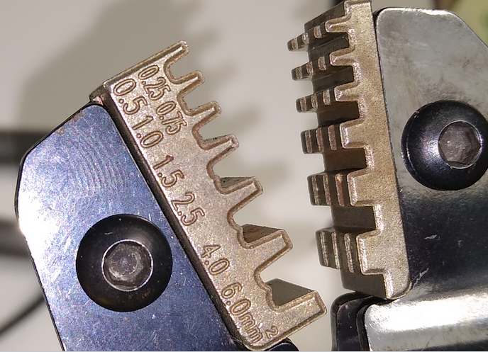
      It could just be they are an size my crimp tool dose not support properly;

      0_1566169220506_tool.png

      Besides that was not the main reason the connector pins failed after 1 year.

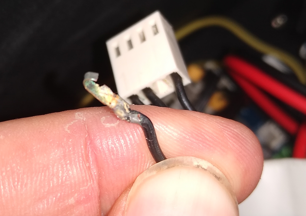
      See below .... Corrosion on the original Duet Dupont Connectors I fitted 1 year ago.

      0_1566168883255_corrision1.png

      This is because i find the supplied connectors from Duet ropey so I usually put a small spot of solder to hold the cable in place while I crimp it as the pin either is just a fraction too big for the slot or a fraction too small and twists in the crimp tool.

      This where I think I found the root cause ..... schoolboy howler ... I borrowed the flux from a neighbour while I waited for my amazon order to arrive.

      I just asked him to show it to me again ...

      0_1566169528521_flux.png

      This is probably the reason why the pins on the Duet connectors have failed... plumbers flux must have reacted badly with the pins and caused them to corrode, weaken and break off in the plastic Dupont connector.

      Doh Doh Doh!

      I have just replaced all the connector pins with new ones soldered with a tiny dab of electronic PCB flux and led solder(Pb 38, Sn 60, Cu 2).

      Its all working now.

      ... it was just really bad luck breaking the same pin on the new cable :-@

      posted in Duet Hardware and wiring
      simonboydfoleyundefined
      simonboydfoley
    • RE: Strange Behaviour from DuetWiFi Extruder Stepper [Solved]

      @bearer Yes I know .... but the contact was good enough and enabled me to experiment with different pin outs.

      I have a 2mm pitch JST Kit turning up on Tuesday.

      I am now trying to prove the E0 Driver has blown.

      I have gone back to a stand Z Driver setup and stopped mapping P4 (E1) to the Z Stepper driver so I could try to use it as the default Extruder instead of P3 (E0).

      Not managed to get the software to use E1 instead of E0 yet ....
      Watch this space.

      If it all works we know its a faulty Board 😞

      posted in Duet Hardware and wiring
      simonboydfoleyundefined
      simonboydfoley
    • RE: Strange Behaviour from DuetWiFi Extruder Stepper [Solved]

      Could be a red herring but it looks like one of the board SMC components has failed.

      This board is mounted upside down so its not possible for something from the power supply to fail and drip onto the duet.

      I cleaned this gunk off the corner of the Driver Chip on the E0 Extruder chip but the problem still exists.

      That looks like a 220 Ohm resistor next to the chip not a cap I have never seen a resistor blow like that, so I'm wondering if its come from under the Chip.

      I'll have to look up the wiring of the chip and seeing if it could have been damaged by that pin.

      0_1566150110153_gunk.png

      posted in Duet Hardware and wiring
      simonboydfoleyundefined
      simonboydfoley
    • RE: Strange Behaviour from DuetWiFi Extruder Stepper [Solved]

      @Stephen6309 I know that is the obvious assumption.

      However this was working fine! And this is the original motor.
      I have not changed the cabling.
      And I have not changed the settings.
      I also have not upgraded the firmware (knowingly).

      0_1566143336348_config.g

      I have also just run in a new cable and it behaves exactly the same!

      0_1566143065339_Duet.png
      0_1566143077333_Extruder.png

      It's Bizarre .... I can start playing around with the pin combinations on my spare motor ....but this looks like its all down to the Duet Wifi and its a board / driver fault.

      If it was the cabling then I would expect to see the voltage either "all positive" or "all negative" on Red-Blue Green-Black pairs ... because the extruder goes in just one direction when telling the duet to extrude.

      What I see the driver doing is go +/- polarity before ending up + at the end of the extrude command.

      posted in Duet Hardware and wiring
      simonboydfoleyundefined
      simonboydfoley
    • Strange Behaviour from DuetWiFi Extruder Stepper [Solved]

      I'm still troubleshooting, but If anybody has any ideas that could help I would appreciate it.

      Basically my CR10s was working fine with the Duet for 6m.

      I take a break for 6m and then I notice that my Extruder motor just goes back and forth continually (constantly reverses polarity back and forth).

      I have not changed anything.

      I replaced the NEMA Stepper Motor ( with a new one ... same issue)
      Also note I replaced it with a correct CR10 Extruder motor MS17HD6P4150

      https://www.moonsindustries.com/p/nema-17-standard-hybrid-stepper-motors/ms17hd6p4150-000004611110008904

      so that the cable cross on pins 3 (Blue) and 4 (Green) is still required.

      I test the cable from the connector on the DuetWifi to the Female connector on the Motor and it passes a continuity test OK.

      I place a multimeter on the end of the cables on the connector that goes into the motor and perform a test extrusion.

      I can see its the Duet Wifi that is constantly reversing the polarity on both coils (Red-Blue) and (Green-Black).

      Any ideas why teh DuetWifi would suddenly start behaving like this ?

      Next Steps: I was going to run a new connector cable directly from the Extruder Motor to the Duet in case its a dry joint in the cable somewhere making it hard for the Duet to maintain a constant current.

      #baffled.

      posted in Duet Hardware and wiring
      simonboydfoleyundefined
      simonboydfoley