Piezo20 probe and piezo kit now available
-
Wow, a world of difference using this probe after a couple of minutes setting up:
…This is what I got with DC42's sensor AFTER spraying my aluminium heat bed with black matt paint and probing my Printbite (the sticky tape makes it a bit patchy as in the photo - is this causing the problem?):Yes, the variable reflection from the sticky tape is the problem. With PEI you have to spray paint the back of the PEI matt black, cure it in an oven, then stick it painted side down to the bed plate. I imagine PrintBite is similar.
I can confirm I had issues with print bite and IR sensor when the PB was mounted directly on aluminium plate
-
I've only skimmed this a bit tied up, but do you need the H2's in your bed. G?
Edit Yes I suppose you do, I haven't used RRF on a cartesian machine. Hmmm…
Not exactly on topic but have you tried the probe on digital instead of analogue, with low debounce value? You can probe at a higher speed with no false triggers.
I posted my M558 and G31 on a previous page.
I removed the H2 and the auto bed compensation graph was higher, but still under z0. Did a probe, which still showed as also under the bed, went to print and the print head wants to start at somewhere around z-5.
Had enough for today. Will try digital tomorow.
-
I've been thinking about effector mounting of piezo sensors as opposed to the under bed sensors that I'm using at the moment, here's what I've come up with.
For a long time now I've been mounting my hot end so that the nozzle is as close in height to the arm mounting as possible. I've been doing this for a couple of reasons:
I hate losing build height, I regularly print things that scrape the top of my Kossel Minis 230mm build height, with an underslung hot end I'd probably lose 50mm or more.
I think that a smaller distance between the arms and the nozzle will minimize effector tilt.
With that in mind, here is the first prototype of my integrated piezo effector.


I've soldered brass M3 nuts to the back of the piezo disks which avoids having to drill holes in them. Unfortunately I can't test this on my printer at the moment, my printer is set up with metal balls on the arms and cups on the carriages and effector, I need to swap them around but I'm waiting on more steel balls.
Idris
-
Its amazing what a day away does…
Nozzle diving below print bed - problem solved.....
Given it was probing nicely, turned my attention to the G-CODE file.
G21 ;metric values
G90 ;absolute positioning
M82 ;set extruder to absolute mode
M107 ;start with the fan off
G28 X0 Y0 F6000 ;move X/Y to min endstops
G28 Z0 ;move Z to min endstopsRemoving the G28 Z0 from the code seems to fix it, and it prints at the right height. Now I need to figure out why......
-
What are you using as your z_min endstop? Is it the piezo probe or do you have a mechanical endstop also?
-
It's the probe…...
-
probably makes no difference but why home xy and then z?
Why not just do G28?
You don't need the X0 Y0 coordinates.I doubt thats it but worth a try, also I'd do your Z home at bed centre so maybe
G28 XY F6000
G1 Xx Yy F6000
G28 Z -
New Piezo Z-probe boards are in as well as Piezo Endstop boards if anyone wants to give those a try.
Idris
-
These piezo's are tough units (using 27mm). In fiddling around, the + wire became detached from the centre (pulled the white stuff off)- thought I'd reattach/solder and hope. Well works fine!
After some more meddling, I am now getting really good results.
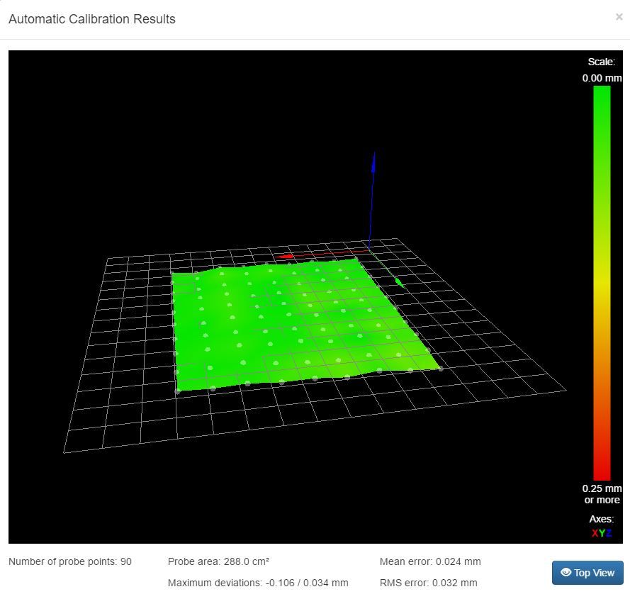
This is the best bed mapping that I've ever had on the printer since running duet wifi.
-
Excellent results that's very satisfying.
Yeah they are quite tough the piezo's. On my test rig I've slammed it into the test bed so hard and so many times, it broke the bracket holding the module, but the piezo was still working like a champ. I've had a few de-soldered wires but soldered them back on with little or no drama. One of the issues moving this forward into a consumer unit is the fragility of the soldered connections on the piezo. My thinking is integrate the control board into the sensor module, thereby reducing the mobility in these wires to zero. It also reduces the (theoretical at this point) risk of interference on the lead to the piezo causing issues. There is another idea involving making the piezo part of the circuit and placing that in between the two parts of the assembly.
-
Talked to a few people at MRRF and handed out some piezo's to a couple guys who had ideas about how to cut the holes more precisely, without any damage. Hopefully I'll have more info on their results soon.
-
That sounds great. Mike (Leadinglights) has developed a method of cutting them on a lathe. Reasonably neat cuts too. That being said none of the discs I have drilled have failed to perform initially or since.
I hope at some point we can source or have made piezo's with holes in at manufacture.
-
Okay so Idris and I are getting closer to having a drop in module ready. More or less settled on the design, just a bit of tweaking. It's done several thousand probes on the rig with no issues. Very stiff as it turns out you don't need any noticeable vertical compliance to get a trigger. Idris is making a custom pcb for it.
Should be a case of remove hot end, insert module between hot end and extruder/carriage and then plug in your endstop wire. It's for groove mount but could be easily adapted with a few bolt holes for screw mounting.
It's small around 30x20x18mm. Should illuminate on trigger (but will also make a solid colour version also).
Aiming for around £25 delivered (UK) for final version. The initial units will be considered beta units and be £19.99 delivered (UK) on the assumption we will get some feedback on improving the product.
International postage will be by individual postage quote.
-
So this would be a piezo with a hole for a bowden, and you just drop it over the top of your groovemount (around the bowden)?
-
So the idea is this is a module which will sit between the groovemount in your effector/carriage/extruder such as a titan, and your hotend. It will have just a 3 wire endstop connector on it. Its pretuned and tested on my rig. If you are using one in a chamber or your ambient temp is 35 deg C+ then let us know we will tune one for higher temp environment, or leave the PCB adjuster with no threadlock on it so you can tune it yourself.
If using bowden, you'd just feed your bowden tube through the middle, there will be space to attach and tension the bowden tube on the hot end, as well as remove the hot end without dismantling the module. If using direct I will supply a short length of bowden tube to use as a filament guide from extruder down into the hotend.

This is what it looks like in my test rig. If you don't want groovemount I'll do a version with captive nuts and bolt holes for direct mounting to underside of a carriage or effector. Almost no compliance of the nozzle in this design, the piezo is pre-tensioned quite firmly.
The new custom PCB will be attached to the back of the module for the transparent version and it will light up the module when powered and hopefully change colour when triggered. If preferred a solid colour version will also be available with the pcb on the front (you can insert the module into your printer whichever way around you want) so it will show two LED's one for power, one for triggered.
This module completed 2000 probes on the rig with no issues. I intend to do a test run of 36800 probes which will simulate a full year's use in a heavy-duty-cycle environment, based on doing 16 probes on a delta to autocalibrate each print, and doing 10 prints per day for 46 weeks per year, 5 days a week. This is likely to represent 3+ years of use in a slightly more normal environment.
-
DJ think there is a typo and you mean 5 days a week and not 5 days a year
-
LOL fair enough edited. Also that didn't multiply up to 38000, it was 36800 probes (edited), I was doing that from memory. Its done 2000 already so another 34800 to do, surprisingly it only takes around 30 minutes to do 1000 probes. I'd leave it going all day whilst I'm at work but if the module fails I am not sure how the rig will deal with it, so I need to do them whilst I'm around and about.
-
This is what it looks like in my test rig. If you don't want groovemount I'll do a version with captive nuts and bolt holes for direct mounting to underside of a carriage or effector. Almost no compliance of the nozzle in this design, the piezo is pre-tensioned quite firmly.
I'd be interested in a non groovemount one, I've been playing around with one of Moriquendi's boards on my reach 3d. Although it is groovemount, it mounts sideways onto a plate, so I reckon it is a good candidate for removing the grovemount. I'd just need to design some sort of interface to the captive nuts and my side plate.
My current setup is a bit bodged together (plate between the groovemount adapters, it does sort of work, but not as well as I'd like.

-
This sounds really cool, but almost one of those "if you ask how to make it work, you probably can't figure it out" type of things. I am quite interested in trying one of these sensors. While I do like the IR sensor a lot, it would be very nice to be able to use on any type of surface. Is it possible to mount this on a cartesian printer? My printer is quite small so if the hotend gets offset much, it will likely cause a loss of print area available.
-
Jmg123,
No problem whilst I haven't made a screw mounted one yet its not a problem. Please give me a shout in a week or two when we're ready to start sending some out and I'll make you one.
Just a question it might be the angle of the photo but what do you do with the inductive/capacitative sensor on its side? Or is it just stowed out of the way for now?
ScotY
Yes its possible to use it on any type of printer. The module sits below the carriage/effector and the hot end clamps into it.
Please let me know once they are released if you want one. I will post something here, and on reprap forum we will have a support/order thread.
