Leveling the bed...
-
Hello all! So I've got the printer up and running and got my SN04-N sensor hooked up and working. I am looking for opinions on the results of the automatic bed compensation and the mesh grid compensation. Should I be concerned and if so what can I do the resolve the issue which should be apparent from the images.
Thanks in advance!
4 point calibration:

5 point calibration:

240 point mesh calibration:

Thanks,
TomTronXY X5S-500 (CoerXY)
Duet 2 Ethernet v1.04
Firmware Version: 2.02(RTOS) (2018-12-24b1)
Web Interface Version: 1.22.6
7" PanelDue
E3D V6 Clone
MOSFET's for hot end
1000w Keenovo with SSR for heat bed
dc42 Mini IR Sensor or BLTouch -
Is this a Cartesian style printer? It looks like you may have some sag on the x axis rods.
If you do a test print with that 240 point mesh does the compensation effectively counter act the bow and print a good first layer?
-
Thanks for the reply, I should have mentioned it's a CoreXY (Tronxy X5S). I am running a Benchy test print right now, I had adhesion issues but the layers looked correct and the Z axis was moving while printing the layer. I'll know in a while, I used Simplify3D with high settings so it's taking a bit. It's also printing support material because I forgot to deselect that option.
")
-
Regardless, it looks like sag on the X axis. That's what mesh compensation is for, taking an imperfect mechanical situation and compensating for it.
-
Well this is a bit better:
4 point:

5 point:

240 point mesh:

The printer (still needs some cleanup):

I received some advice from a Tronxy reseller in a Tronxy Facebook group. The screws that hold the linear rods in the top of the frame were overtightened. I loosened them and the bed became much more level.
-
What is the bed made of and how is it mounted? I seem to recall seeing some other posts about the Tronxy bed being mounted with many bolts which make it difficult to get level. Ideally, you'd only have 3 screws.
https://drmrehorst.blogspot.com/2017/07/3-point-print-bed-leveling-vs-4-point.html
-
The bed is a MK3a heated aluminum type with a 0.5mm build mat a adhered to it. Here are some pictures of how it's mounted, a picture being worth a thousand words.


-
Yes that bed will be a challenge to level. It's not very thick or stiff, and it has 6 screws trying to tame it.
From your detailed probe it would seem that the front middle screw needs to be tightened a bit.
-
Thanks for the help! Is it possible to update bed.g to do more than 5 points? It would be nice to do more points on the perimeter to dial it in and then run the mesh.
-
Instead of using bed.g and fixed points it may be better to use G29 for mesh grid compensation. You can specify a grid to probe, and rather than just trying to make a level plane it creates a height map of the surface and adjusts the print head distance continuously during the first layer and for several layers afterwards.
-
Thanks, I've been using automatic bed compensation to dial it in as it is faster and then running the 240 point mesh when I got it close. I still want the 240 point mesh compensation but for dialing it in it would be helpful if I could add the center of each run as well, so nine points around the perimeter and the center.
-
I've changed to a BLTouch sensor (and an E3D V6 clone but that probably doesn't impact this
), the difference in the results are interesting. I think I'll pick up a piece of borosilicate glass and see what kind of results I get.
-
@tletourneau What values are you using for M558?
-
@phaedrux said in Leveling the bed...:
@tletourneau What values are you using for M558?
M558 P9 H5 F0 T6000
I would like to figure out how to do the fast/slow setup with the BLTouch where it moves up fairly quickly and triggers the probe then moves down a bit and comes up slowly to get a more accurate reading. I think it would cut down a bit on the mesh probes.
-
Are you actually using F0?
Try this
M558 P9 H5 F100 T6000 A5 R0.3 S0.005 B1 G31 P25 -
@phaedrux said in Leveling the bed...:
Are you actually using F0?
Try this
M558 P9 H5 F100 T6000 A5 R0.3 S0.005 B1
G31 P25
Thanks, I'm giving that a try now. I've also calculated my average Z offset and added it to the G31 so my gcode looks like this now:
M558 P9 H5 F100 T6000 A5 R0.3 S0.005 B1 ; Set Z probe type to bltouch and the dive height + speeds G31 P25 X-42 Y-4 Z-0.50 ; Set Z probe trigger value, offset and trigger height -
I'm concerned that your z offset is negative. How did you measure it?
-
@phaedrux said in Leveling the bed...:
I'm concerned that your z offset is negative. How did you measure it?
I had the printer at Z0 and issued a M208 S1 Z-3, I then moved the print head to the center of the bed and placed a small sheet of paper between the hot end and the bed and raised the bed until there was a slight drag on the paper. I then checked the Z reading on the display which was -0.50. I did the same thing for each screw location along with X20:Y165 and X325:Y165. I manually adjusted the levelers until the perimeter and center were all at Z-0.50. I was under the impression that this should be done to account for the trigger height variance. I could possibly adjust the probe mount to compensate for the trigger height variance but I did not want to introduce other variables by messing with the mount.
Thanks,
TomTronXY X5S-500 (CoerXY)
Duet 2 Ethernet v1.04
Firmware Version: 2.02(RTOS) (2018-12-24b1)
Web Interface Version: 1.22.6
7" PanelDue
E3D V6 Clone
MOSFET's for hot end
1000w Keenovo with SSR for heat bed
dc42 Mini IR Sensor or BLTouch -
@tletourneau Maybe you want to consider a different reason for your funny looking printbed heat map: the trapezoid screws which connects the spindles to the frame of the heat bed are not backlash free, so when your stepper changes direction, you will have some error everytime. When you move down, steps are lost by moving the screw from the bottom flank to the upper of the screw. The printer thinks the bed to be lower than it is in reality. You can test it by forcing the bed and screw to be always at the bottom of the spindle by putting some 2 kg weight on the heat bed and testing again. (Generally, the heat bed is always at the bottom by the bed weight, but you have a stiff construction, so spindle-bed-spindle could have some tension and could clamp the screw to remain on top). I measured my spindle backlash to be 0.1 mm.
-
@tletourneau It's just that with this probe type it expects the probe to trigger before the nozzle reaches the bed, and a negative value may be converted by the firmware to a positive value anyway.
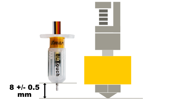
Furthermore, the BLTouch needs to be mounted with the base of the probe body 8mm above the nozzle tip which should result in a trigger height close to 2mm.
With such a constrained bed with 6 leveling screws it will be difficult to prevent some warping. Have you tried removing 3 of the screws to allow for a 3 point leveling system?