Closed Loop Control of Stepper Motors with Rotary Encoder
-
@aj-quick What about option that I linked? It also does the all-in-one w/ the appropriate stepper motor (that has encoder included) and expansion header from the Duet.
-
@sean said in Closed Loop Control of Stepper Motors with Rotary Encoder:
That should work with the Duet, although you will probably need to use the expansion breakout board to boot the output current for the step, direction and enable signals.
-
@dc42 said in Closed Loop Control of Stepper Motors with Rotary Encoder:
That should work with the Duet, although you will probably need to use the expansion breakout board to boot the output current for the step, direction and enable signals.
We have already reached out to Roland to order the breakouts. Though he did direct us to this post: https://forum.duet3d.com/topic/1501/duet-expansion-header-breakout/9. I am hoping the appropriate R setting in M569 will remedy any issues.
We currently use the M400 command to identify when the last G1 command has finished (add M400 after G1 ... so that the "ok" from M400 doesn't respond until G1 completes, given that we are under Marlin compatibility mode).
@dc42, with the external stepper driver, will we see the same type of behavior from the Duet? Meaning, if we use the breakout to send the logic commands to the external driver, will the Duet know when the move has completed and send the 'ok' back only after the desired position has been reached?
What happens if there's a missed step (the entire reason for the closed loop system), will the Duet lag behind and send off the next command?
-
I suppose the driver you linked will work. The servo will complete its movement when the system stops sending step signals. It will be the same as a stepper motor.
You can hook up the feedback trigger for error into the e-stop for that particular axis and then setup a trigger to run code when the servo error is triggered though. So if for some reason the servo is unable to complete its motion (stuck motor for example) it will send an e-stop signal.
-
This comes up a lot... and I have to ask... what problem are you trying to solve?
Hundreds of Thousands? of 3D printers and small CNC machines never miss a step in their normal operation. If they do, it is because of a loose belt or a total jam or something else a closed-loop to the motor won't fix.
Why add expense and complexity to something that works?
Apologies in advance if you have a unique application...
-
@sean said in Closed Loop Control of Stepper Motors with Rotary Encoder:
@dc42, with the external stepper driver, will we see the same type of behavior from the Duet? Meaning, if we use the breakout to send the logic commands to the external driver, will the Duet know when the move has completed and send the 'ok' back only after the desired position has been reached?
The "OK" response to a M400 command won't be sent until the M400 command has completed, which won't happen until all moves commanded prior to the M400 command have completed.
-
@aj-quick said in Closed Loop Control of Stepper Motors with Rotary Encoder:
I suppose the driver you linked will work. The servo will complete its movement when the system stops sending step signals. It will be the same as a stepper motor.
You can hook up the feedback trigger for error into the e-stop for that particular axis and then setup a trigger to run code when the servo error is triggered though. So if for some reason the servo is unable to complete its motion (stuck motor for example) it will send an e-stop signal.
Based on @dc42's response below, that seems to be the case. The error catching will be enormously helpful. I ordered the part I linked and will get it next week.
-
@danal I wouldn't say "won't fix" because when we deploy our product it will be difficult to service without incurring a lot of costs (travel or shipping, as an example). Closing the loop on the motion system is peace of mind to know that the duet and external driver are working together to maintain the expected position. And then when something off nominal happens, like a loose belt, or a bit of zip tie, or w/e pops up in the environment, the external driver's fault feature will allow us to shut the machine down before it damages itself extensively.
Absolutely appreciate the question, and it is a good point to remind us that the external driver doesn't solve design flaws or assembly errors that may lead to an issue. We still need to be conscious of our choices there.
-
This post is deleted! -
@dc42 I received the external driver and expansion board. I have not had any luck getting it to work so far.
Driver = https://www.omc-stepperonline.com/index.php?route=product/isearch&search=CL57T
Setup=
(Driver) to (Duet Breakout) on Drive 5
PUL+ to STEP+
PUL- to STEP-
DIR+ to DIR+
DIR- to DIR-
ENA+ to ENA+
ENA- to ENA-From my config file:
; Motor Remapping
M584 X5 Y1:2 V0 U3 Z4;; Drives
M569 P0 S1 ;
M569 P1 S1 ;
M569 P2 S1 ;
M569 P5 S1 R1 T2;M906 X2000 Y2000 Z0 U0 ; Set motor currents (mA)
The stepper motor has encoder feedback, so first I connected only the stepper motor wires (A+/- B+/-) to the Duet and commanded the stepper motor just fine. When I plug the stepper into the external driver, I noticed that the stepper motor gets hot (about 55+ C) after 10 minutes. That seems to be too high (also data sheet says- 20 to 50 C). I checked the amp setting in M906, and you can see its 2A, as suggested in the motor spec sheet.
For the dip switch settings, SW1-SW4 are simple, they just control the encoder resolution (set to default for now). SW5 to SW8 though, I am having a hard time understanding their connection to the config.g settings under M569. In the GCode documentation it says "backwards" or "forwards" for the S parameter - how does this relate to CW or CCW as the Driver seems to indicate?
Currently, with the dip switches all set to OFF, I have (on the ext. driver)
DIR=CCW,
Auto Tuning = Yes,
Pulse Mode = PUL/DIR, and
Pulse Edge = RisingWhen I command a X+1 movement from DWC, the shaft seems to click forward, but if I do it another time the movement isn't the same, and a third X+1 causes the motor to vibrate erratically.
Any guidance you can provide would be greatly appreciated!
-
@sean your motor gets hot because you set 2A, which is too much. Please see https://forum.duet3d.com/topic/3073/what-should-i-set-my-motor-currents-to-via-m906/3 or similar threads, to set between 50 and 80% of 2A.
After getting too hot (> 80 °C internal) the neodym magnets get damaged. I would check that the stepper is still ok. You can measure the A+/- and B+/- resistance and compare it with the datasheet information.
-
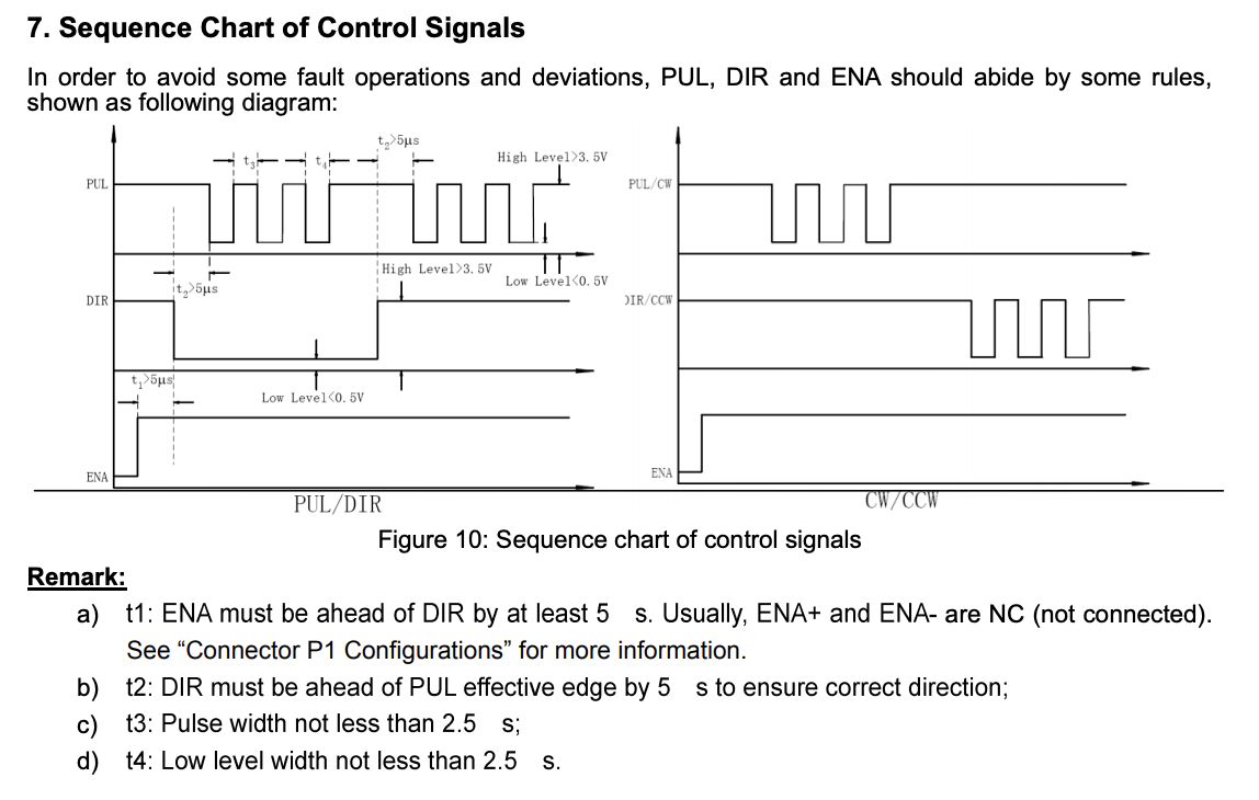
@sean Based on this diagram from the driver data sheet:

I updated my M569 command to:
M569 P5 S1 R1 T2.5:2.5:5:0
On the external driver I have the Motor DIR set to CW, and the S1 parameter in M569 set to "Forward" because that seems to make sense.
R1 set to Enable High, because enabling the driver from the chart looks like a high command.
And the Step Pulse timing seems to correspond to:
Taa:bb:cc:dd (firmware 1.21 and later)
aa: Minimum driver step pulse width, t3
bb: step pulse interval, t4
cc: direction setup time, t2
ddL direction hold time, 0This is still causing my motor to vibrate after 1 or 2 X+1 commands.
-
@joergs5 Thanks for the response. I adjusted my R parameter in M569 to R1, active high, and the motors seem to stay cool.
-
@sean I followed the steps on this post, to see if the voltage coming from the expansion breakout was too low for my ext. driver. I didn't suspect so, and it didn't change the behavior of the motor.
-
@sean Maybe you should split your analysis first to know which component is not working correctly, so using this controller with another stepper and then testing the stepper with a different controller.
The controller has ALM connections. I remember a discussion about this setting here:
https://forum.duet3d.com/topic/3519/yet-another-external-driver-question/2
(different controller, but maybe comparable meaning). -
@joergs5 That approach makes sense - my hang up is that i don't know if the settings on the Duet are matching the dip switch settings on the external driver. Questions like fwd v. CW, or Pulse edge rising v. falling, etc.However, I will mix & match drivers w/ motors to see if the issues are consistent.
I don't believe ALM has any bearing on the issues I'm facing. The ext. driver has a flashing LED that tells me when there is an issue, so the ALM connections are just to notify you elsewhere, such as activating a trigger on the Duet as @dc42 points out in the post you linked.
-
@sean Some more ideas: if your tests give no result, you could provide information how your wiring is: which pins you connected, which PSU and connected where (controller for stepper needs 24-48 V e.g.), especially where you connect the + signals. Your T parameters are at the edge of the minimium values, I would try longer times.
(In case you don't know) CW means clockwise, CCW counterclockwise, so I would set this switch to PUL/DIR.
I would not set/use ENA, because it is enabled if unconnected.
-
@joergs5 , the external driver has a dip switch for
"SW5, Motor DIR: off=CCW or on=CW"
"SW7, Pulse Mode: off=PUL/DIR or on=CW/CCW."I currently have it set to PUL/DR and CW to align with the Duet firmware "Forward." (This makes more sense to me than CW aligning with Backward).
-
@sean If you have an oscilloscope, looking at the signals would be another idea. I bought one myself (Hantek 6022) to look at controller signals. Not a quick solution, but maybe you experiment as often as me so that it pays off...
There is a youtube about CL57T, maybe you get some hints:
https://www.youtube.com/watch?v=S8c6c4CYZUU -
Update: I believe the issue was the external driver had a default amp setting of 8A, and the stepper motors I was using were only 2.0 A. When I finally was able to get into the external driver firmware (pro tip: order the RS232 compatible cable AND a serial-to-USB from amazon or something), I could toggle the amperage setting from 8A to 2A and create or turn off the vibrating motor issue I was experiencing.
With the omc-stepperonline driver and stepper motors, the pulse timing in M569 is set to 7.5. Anything less and the stepping from the motor sounded like grinding. 7.5 sounds pretty smooth.