Update: Found 90v AC 3- Phase drives. Testing one soon!
Best posts made by DoodleCube
-
RE: Fanuc Arcmate to 3D printer- Servo Wiringposted in Duet Hardware and wiring
Latest posts made by DoodleCube
-
RE: Need help with 5 Bar SCARA configurationposted in Firmware installation
Quick update! It works! It looks like my issue was with my external drivers. For some reason despite them being also set to 64 microstep I had to cut the steps per mm in half. I have since moved the working arm to its own electronics and it is now running on RRF 3.4.6. I had initially wished to run this on the latest release, but it seems RRF3 on Duet 2 stopped supporting 5 bar kinematics to save space for new features.
Since this is the case, Im hoping to run across some documentation on how to import/disable kinematic binaries to these boards for future-proofing my new project.
-
RE: Need help with 5 Bar SCARA configurationposted in Firmware installation
Good to see you! Yes that is the page I started from. Playing around with the config yesterday I was able to get it to home by updating the homing values. I will post an updated version of my config that sorta works to show what I have now. I can move the arm in the workspace, But after homing and jogging the arm back to center, It reads -44 on X and 99.6 on Y, when both arms should read around 45 and 135.
Also, currently moving in positive Y pulls the arm closer to the motors, and Y travel is in a skew to the left.
I did see that in the motor testing section the X motor which for me is the right motor, should turn counterclockwise when given a relative X+ movement but that seems to invert once absolute position is called.Parts of my config are below, Please let me know what im missing.
Thanks!
M92 X355.55 Y355.55 Z400 ; configure steps per mm
M208 X-60:360 Y-60:360 Z0:250 ; set minimum and maximum axis limitsM669 K9 X-32.5:32.5 Y0:0 L2 P110:110 D140:140:0:0 B200:90 C80:200:0:150 Z-180:-180:180:180 ; configure 5 Bar Parallel
M574 X1 P"xstop" S1 ; configure X axis endstop
M574 Y1 P"ystop" S1 ; configure Y axis endstop
M574 Z1 P"zstop" S1 ; configure Z axis endstop
SCARA kinematics -
RE: Need help with 5 Bar SCARA configurationposted in Firmware installation
@droftarts hello Ian, currently I am working on RRF 3.4. I have since swapped the X actuator to the right side following some clues on other forums. While I have the steps/deg close it's not perfect. I'm using planetary gearboxes so im not 100% sure the tooth count math is accurate.
-
Need help with 5 Bar SCARA configurationposted in Firmware installation
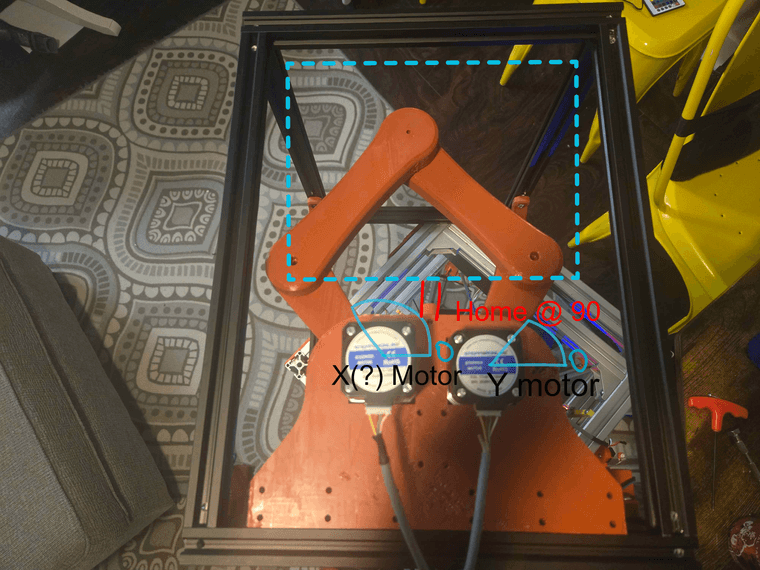
Hello again everyone! Im working on a 5 bar scara and I am a little bit confused on the documentation. I will have my current config posted here, but my plan is for a small 180x180mm build volume scara with planetary gearboxes and a preloading mechanism to reduce backlash. As i have designed all the parts to be 3d printed, I have all the measurements I need to ensure the kinematics work..but they dont. I am having doubts about my understanding of the documentation. Below is an example of how I am interpreting it. X being the left actuator and Y being the right actuator. My initial goal was to home the arms at 90 degrees with two endstops on a bracket that hangs down to trigger on the inside of the proximal arms. When it does home, the kinematics fail and I get the position unreachable error. Sometimes it does home, with X at 30 degrees and Y at 243 degrees. I want to make sure I am reading everything correctly before I keep working.
Config:
M92 X355.55 Y355.55 Z400 ; configure steps per mm
M208 X0:360 Y0:360 Z0:250 ; set minimum and maximum axis limits
M669 K9 X0:65 Y0:0 L2 P110:110 D140:140:0:0 B90:90 C80:200:100:-17 Z0:100:250:250  ; configure 5 Bar Parallel SCARA kinematics
M574 X1 P"xstop" S1 ; configure X axis endstop
M574 Y1 P"ystop" S1 ; configure Y axis endstop
M574 Z1 P"zstop" S1 ; configure Z axis endstop
I think that is everything. I will provide anything else that might be needed. Thanks!
-
RE: Fanuc Arcmate to 3D printer- Servo Wiringposted in Duet Hardware and wiring
Update: Found 90v AC 3- Phase drives. Testing one soon!
-
RE: Fanuc Arcmate to 3D printer- Servo Wiringposted in Duet Hardware and wiring
@T3P3Tony Its worth a shot, I like this kinda pain

-
RE: Fanuc Arcmate to 3D printer- Servo Wiringposted in Duet Hardware and wiring
The servos are 3-phase 90v 2.5 amp AC. Motor spec is A06b-0371-B155. I found some 3 phase drivers on stepperonline that might do the trick, if rectified or stepped down. It seems the original configuration included amplifiers, which I am not sure I can bypass. It may genuinely be easier to swap it all with similar size DC closed loop steppers if I can remove the servo's pinions easily enough. I will admit- my experience stops at closed loop nema 23s. I really would like to drive the original motors, but the Fanuc drivers well over 2k each. There has got to be another way to drive these, they are servos after all.
-
RE: Fanuc Arcmate to 3D printer- Servo Wiringposted in Duet Hardware and wiring
@dc42 The servos do have encoders built in but not full drivers. I bought the arm of an industrial liquidation company and its just the arm without the controller.
-
RE: Fanuc Arcmate to 3D printer- Servo Wiringposted in Duet Hardware and wiring
I have found 2 possible drivers. Both are 3-Phase, but one is the correct 90v and 2.5 amps but its DC and only for NEMA 23s, 24s, 34s, while the other is AC, for NEMA 42s and 52s but is 176v-253v. Is it possible to rectify the DC signal to AC or would it be better to use the AC driver and reduce the voltage? My servos are 3-Phase 90v AC servos rated for 2.5amps
-
RE: Fanuc Arcmate to 3D printer- Servo Wiringposted in Duet Hardware and wiring
@Maestro Would swapping them be a viable option? I looked at drivers, and it will probably cost quite a bit unless I get lucky again. If these drivers are the only way, I can probably do it, just not sure which path would be easier/better