Never mind. I got it working. The issue was with the time delays.
Chinese documentation:
M569 P41.0 S1 R1 T2.5:2.5:5:5
Reality:
M569 P41.0 S1 R1 T6:6:6:6
Never mind. I got it working. The issue was with the time delays.
Chinese documentation:
M569 P41.0 S1 R1 T2.5:2.5:5:5
Reality:
M569 P41.0 S1 R1 T6:6:6:6
@infiniteloop
Endstop is wired to IN and GND pins of IO_2 connector.
@Phaedrux
Thanks. I used M84 E0 at start of homing codes and it did the job. Now it is working correctly every time.
Yes, the endstop wire is shielded, and the switch is a simple normally closed micro-switch, as recommended.
I’ve also noticed something very specific:
Right after powering on or resetting the controller, homing works perfectly — regardless of the axis position.
However, after performing an extrusion (extrude command), homing no longer works properly — the axes stop too early, as if the endstop had already been triggered.
Could this behavior be caused by interference from the extruder motor?
The endstop wires are routed separately from the extruder motor cables, so they don't share the same path.
Would it be possible to reset the extruder driver via G-code after each extrusion or print to prevent this issue?
@fcwilt The homing code for the X axis appears to be correct.
The working area of the machine is X1200Y2300 mm, and in the homing file, the G1 command for X is set to -1205 and Y -2305, which seems appropriate given the dimensions.
Here is the relevant portion of the homing code for X:
G91                ; relative positioning
G1 H2 Z10 F3000    ; lift Z relative to current position
G1 H1 X-1205 F3000 ; move quickly to X axis endstop and stop there (first pass)
G1 H2 X5 F3000     ; go back a few mm
G1 H1 X-1205 F1500 ; move slowly to X axis endstop once more (second pass)
G1 H2 Z-10 F3000   ; lower Z again
G90                ; absolute positioning
Is it possible that the cable length (approx. 5 meters) is introducing additional resistance, making the controller interpret the switch as open?
Or could it be due to electrical noise from nearby signal or motor cables?
@infiniteloop said in Homing X triggers before reaching endstop:
Would be good to know whether the move stops due to the endstop being triggered…
Context (please confirm):
You are running a 6HC + 1XD in a SBC setup?
Your config.g is still this here?
Yes provided hardware setup (6HC + 1XD in SBC configuration) and the config.g you referenced are both correct.
We verified the switch using a multimeter and it works correctly.
Also, when we press the switch, the X endstop indicator in DWC lights up green as expected.
What’s interesting is that when the X axis starts close to the switch, the homing procedure works normally.
However, if the axis is farther away, we need to run the homing sequence several times before it actually reaches the switch.
It looks like the system thinks the endstop has been triggered before it actually touches the switch.
I have a problem with the X-axis endstop.
When I perform a homing operation, the axis moves but stops before reaching the X endstop. To actually reach the switch, I have to run the X homing procedure a dozen times.
The switch is connected as normally closed. The cable is quite long, about 5 meters.
The Y-axis also has a long cable, but it works fine.
What could be the cause? How can I fix the problem?
@droftarts At first, I intended to use the 6XD, but I received a pre-wired and configured 6HC bundled with an extruder, so I thought adding 3x 1XD would be faster and cheaper than switching to the 6XD.
Never mind. I got it working. The issue was with the time delays.
Chinese documentation:
M569 P41.0 S1 R1 T2.5:2.5:5:5
Reality:
M569 P41.0 S1 R1 T6:6:6:6
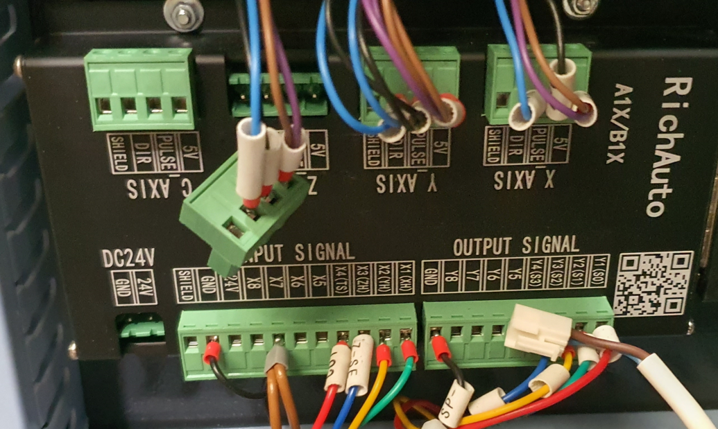
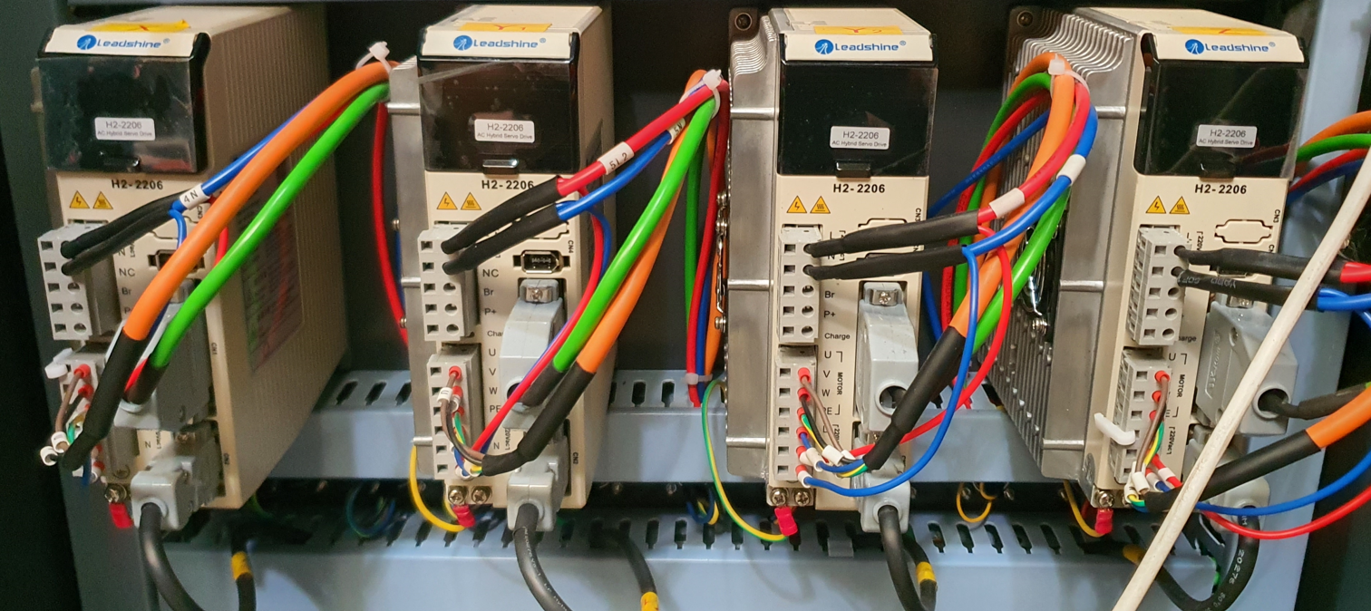
I am generally converting a CNC milling machine into a 3D printer. I want to replace the old motherboard (RichAuto A1X/B1X) with a Duet 6hc and 1xd modules.
The motor drivers are H2-2206, and the servo motors are 863HSM100H. The documentation includes information about pulse times, and they are set in the firmware as follows:
M569 P41.0 S1 R1 T2.5:2.5:5:5
Regarding the connections, +5V is connected to 5V, STEP- to PULSE-, and DIR- to DIR-. The drivers do not have EN inputs.
; Configuration file for Duet 3 (firmware version 3.5.1)
; executed by the firmware on start-up
;
; SBC Config
M291 P"Applying persistent configuration options" R"Please wait" S1 T60 ; show that persistent settings are being configured
while exists(sbc) && plugins.DuetPiManagementPlugin.pid < 0 && iterations < 30
G4 S2 ; wait for DuetPiManagementPlugin to become available
G4 S2 ; wait another moment
M929 S2 ; start logging events to the SD Card
M550 P"MD" ; set persistent hostname for printer
;M551 P"mdrapid" ; set password
M586 P0 S1 C"*" ; configure HTTP & enable CORS
M586 P1 S0 ; disable FTP
M586 P2 S0 ; disable Telnet
M292 ; hide message box again upon completion
; General Preferences
G21 ; Work in millimetres
G90 ; absolute coordinates
M83 ; relative extruder moves
; Drives
M569 P41.0 S1 R1 T2.5:2.5:5:5 ; physical drive 0.0 goes forwards with active high enable config pulses intervals (x)
M569 P42.0 S1 R1 T2.5:2.5:5:5 ; physical drive 0.0 goes forwards with active high enable config pulses intervals (y)
M569 P43.0 S1 R1 T2.5:2.5:5:5 ; physical drive 0.0 goes forwards with active high enable config pulses intervals (z)
M584 X41.0 Y42.0 Z43.0 ; set drive mapping
M92 X83.50 Y83.50 Z320.00 ; set steps per mm
M566 X600.00 Y600.00 Z60.00 ; set maximum instantaneous speed changes (mm/min)
M203 X3000.00 Y3000.00 Z1800.00 ; set maximum speeds (mm/min)
M201 X500.00 Y500.00 Z20.00 ; set accelerations (mm/s^2)
; Axis Limits
M208 X0 Y0 Z0 S1 ; set axis minima
M208 X2000 Y4000 Z320 S0 ; set axis maxima
; Endstops
M574 X1 S1 P"io2.in" ; configure switch-type (e.g. microswitch) endstop for low end on X via pin io2.in
M574 Y1 S1 P"io3.in" ; configure switch-type (e.g. microswitch) endstop for low end on Y via pin io3.in
; Z-Probe
M558 P5 C"io5.in" H10 F900 T3000 ; set Z probe type to switch and the dive height + speeds
G31 P500 X0 Y0 Z8 ; set Z probe trigger value, offset and trigger height
M557 X0:1250 Y0:2400 S200 ; define mesh grid
; PE320 Extruder
M569 P40.0 S1 R1 T0:0:0:0 ; external drive CAN address 40 goes forward, active high enable
M584 E40.0 ; set drive mapping - map extruder to CAN address 40
M350 E1 I0 ; configure extruder with NO microstepping
M92 E301.6485 ; set steps per mm - extruder E-steps/mm (resolution of 1:48) or 166.7 steps/rev
M566 E3000 ; set maximum instantaneous speed changes (mm/min)
M203 E3000 ; set maximum speeds (mm/min)
M201 E20000 ; set accelerations (mm/s^2)
; Temp sensor parameters
M308 S0 P"2.spi.cs0" Y"rtd-max31865" A"Top"
M308 S1 P"2.spi.cs1" Y"rtd-max31865" A"Middle"
M308 S2 P"2.spi.cs2" Y"rtd-max31865" A"Bottom"
M308 S3 P"2.spi.cs3" Y"rtd-max31865" A"Nozzle"
; Create heaters
M950 H0 C"out0" T0 ; create Top heater output on out0 and map it to sensor 0
M950 H1 C"out1" T1 ; create Middle heater output on out1 and map it to sensor 1
M950 H2 C"out2" T2 ; create Bottom heater output on out2 and map it to sensor 2
M950 H3 C"out3" T3 ; create Nozzle heater output on out3 and map it to sensor 3
; Set PID heater parameters
M307 H0 R1.319 K0.319:0.000 D25.28 E1.35 S1.00 B0
M307 H1 R0.650 K0.120:0.000 D35.30 E1.35 S1.00 B0
M307 H2 R0.636 K0.188:0.000 D41.46 E1.35 S1.00 B0
M307 H3 R0.500 K0.137:0.000 D21.29 E1.35 S1.00 B0
; Maximum extruder heater temperature
M143 H0 S400 ; set temperature limit for heater 0 to 400C
M143 H1 S400 ; set temperature limit for heater 0 to 400C
M143 H2 S400 ; set temperature limit for heater 0 to 400C
M143 H3 S400 ; set temperature limit for heater 0 to 400C
; Extruder heater fault detection
M570 H0 P60 T30 ; An anomaly on heaters 0 must persist for 60 seconds, and must be greater or less than 30C from the setpoint, to raise a heater fault.
M570 H1 P60 T30 ; An anomaly on heaters 1 must persist for 60 seconds, and must be greater or less than 30C from the setpoint, to raise a heater fault.
M570 H2 P60 T30 ; An anomaly on heaters 2 must persist for 60 seconds, and must be greater or less than 30C from the setpoint, to raise a heater fault.
M570 H3 P60 T30 ; An anomaly on heaters 3 must persist for 60 seconds, and must be greater or less than 30C from the setpoint, to raise a heater fault.
; Define Heaters as Tools
M563 P0 H0 S"Top"
M563 P1 H1 S"Middle"
M563 P2 H2 S"Bottom"
M563 P3 D0 H3 S"Nozzle"
; Heater Cooling Fans
M950 F0 C"2.out0+io1.in" Q100 A"Heat Break Fan" ; Heat Break Fan -- 4-wire PWM 12V fan so invert it, 100Hz PWM, NO tacho
M950 F1 C"!2.out3+out3.tach" Q100 A"Top Fan" ; Top Fan -- 4-wire PWM 12V fan so invert it, 100Hz PWM, tacho connected
M950 F2 C"!2.out4+out4.tach" Q100 A"Middle Fan" ; Middle Fan -- 4-wire 12V PWM fan so invert it, 100Hz PWM, tacho connected
M950 F3 C"!2.out5+out5.tach" Q100 A"Bottom Fan" ; Bottom Fan -- 4-wire 12V PWM fan so invert it, 100Hz PWM, tacho connected
M106 P0 S1 T40 H0:1:2:3 ; Turn on Heat Break Fans when heaters 0-3 are above 40 deg
M106 P1 S0.5 ; Run at 20% speed at 2200rpm (max 11000rpm)
M106 P2 S0.5 ; Run at 20% speed at 2200rpm (max 11000rpm)
M106 P3 S0.5 ; Run at 20% speed at 2200rpm (max 11000rpm)
; Bed Heaters
;M308 S4 P"1.temp0" Y"thermistor" A"Bed" T100000 B4725 C7.06e-8 ; configure bed thermistor at 1.temp0
;M308 S5 P"1.temp1" Y"thermistor" A"Bed" T100000 B4725 C7.06e-8 ; configure bed thermistor at 1.temp1
;M308 S6 P"1.temp2" Y"thermistor" A"Bed" T100000 B4725 C7.06e-8 ; configure bed thermistor at 1.temp2
;M308 S7 P"temp0" Y"thermistor" A"Bed" T100000 B4725 C7.06e-8 ; configure bed thermistor at temp0
;M950 H4 C"1.out0" T4 Q10 ; create bed heater output on 1.out0 and map it to temp sensor 4
;M950 H5 C"1.out1" T5 Q10 ; create bed heater output on 1.out1 and map it to temp sensor 5
;M950 H6 C"1.out2" T6 Q10 ; create bed heater output on 1.out2 and map it to temp sensor 6
;M950 H7 C"1.out3" T7 Q10 ; create bed heater output on 1.out3 and map it to temp sensor 7
;M307 H4 R0.421 K0.321:0.000 D5.73 E1.35 S1.00 B0 ; Bed PID tuning parameters
;M140 P0 H4 ; map heater 4 to heated bed 0
;M140 P1 H5 ; map heater 5 to heated bed 1
;M140 P2 H6 ; map heater 6 to heated bed 2
;M140 P3 H7 ; map heater 7 to heated bed 3
;M143 H4 S120 ; max temp -- 120 deg C
;M143 H5 S120 ; max temp -- 120 deg C
;M143 H6 S120 ; max temp -- 120 deg C
;M143 H7 S120 ; max temp -- 120 deg C
;M570 H4 P60 T15 ; An anomaly on heaters 4 must persist for 60 seconds, and must be greater or less than 15C from the setpoint, to raise a heater fault.
;M570 H5 P60 T15 ; An anomaly on heaters 4 must persist for 60 seconds, and must be greater or less than 15C from the setpoint, to raise a heater fault.
;M570 H6 P60 T15 ; An anomaly on heaters 4 must persist for 60 seconds, and must be greater or less than 15C from the setpoint, to raise a heater fault.
;M570 H7 P60 T15 ; An anomaly on heaters 4 must persist for 60 seconds, and must be greater or less than 15C from the setpoint, to raise a heater fault.
; Define Bed Heaters as Tools
;M563 P4 H4 S"Bed 0"
;M563 P5 H5 S"Bed 1"
;M563 P6 H6 S"Bed 2"
;M563 P7 H7 S"Bed 3"
; Define Inputs
M950 J0 C"io0.in" ; Relay 12 - Estop
M950 J1 C"io1.in" ; Relay 13 - Reset
;M950 J2 C"io2.in" ; Relay 14 - X-Endstop
;M950 J3 C"io3.in" ; Relay 15 - Y-Endstop
;M950 J4 C"io4.in" ; Relay 16 - Z-Endstop
;M950 J5 C"io5.in" ; Relay 17 - Z-Probe
M950 J6 C"io6.in" ; Relay 18 - FREE
M950 J7 C"io7.in" ; Relay 19 - FREE
M950 J8 C"io8.in" ; Relay 20 - FREE
M950 J9 C"1.io0.in" ; Relay 21 - FREE
M950 J10 C"1.io1.in" ; Relay 22 - FREE
M950 J11 C"2.io0.in" ; Smart Wiring Loom - Material sensor LEFT
M950 J12 C"2.io2.in" ; Smart Wiring Loom - Material sensor RIGHT
M950 J13 C"40.io0.in" ; 1XD board - Servo Drive Fault
; Configure Input Triggers
M581 P1 T2 S1 R0 ; Relay 13 - trigger 2 (Reset) activates on falling edge when Estop button is pressed
M581 P13 T3 S1 R0 ; Trigger 3 (Servo Drive Fault) activates on falling edge when servo fault detected
; Define Ouputs
M950 P0 C"out4" ; Relay 1 - Pellet Material Feed Solenoid
M950 P1 C"out5" ; Relay 2 - Part Cooling Solenoid
M950 P2 C"out6" ; Relay 3 - FREE
M950 P3 C"out7" ; Relay 4 - FREE
M950 P4 C"out8" ; Relay 5 - FREE
M950 P5 C"out9" ; Relay 6 - FREE
M950 P6 C"1.out1" ; Relay 7 - FREE
M950 P7 C"1.out2" ; Relay 8 - FREE
M950 P8 C"1.out3" ; Relay 9 - FREE
M950 P9 C"1.out4" ; Relay 10 - FREE
M950 P10 C"1.out5" ; Relay 11 - FREE
M950 P11 C"40.io0.out" ; 1XD board - Clear Servo Drive Faults
; Set Outputs
M42 P0 S0 ; Output OFF
M42 P1 S0 ; Output OFF
M42 P2 S0 ; Output OFF
M42 P3 S0 ; Output OFF
M42 P4 S0 ; Output OFF
M42 P5 S0 ; Output OFF
M42 P6 S0 ; Output OFF
M42 P7 S0 ; Output OFF
M42 P8 S0 ; Output OFF
M42 P9 S0 ; Output OFF
M42 P10 S0 ; Output OFF
M42 P11 S0 ; Output OFF
; Select Tool
T3 ; select nozzle heater with PE320 extruder
M568 P3 A0 ; set nozzle heater to off
; Custom settings
https://www.control-drive.com/Documents/Manuals/CN/H2-2206_manual_cn.pdf
https://www.scribd.com/document/717854727/H2-2206-manual-cn
https://forsuncnc.com/wp-content/uploads/2021/11/DSP-A11-User’s-Manual.pdf
This is the second milling machine I am converting into a 3D printer. The previous one was very similar, and it works correctly. The motor drivers there were H2-758. I also connected only 5V, Step-, and Dir- there. I used Duet 6xd there. When I measure the step signal during movement there, it shows 0.5V, which is more than on 1xd.
Hi,
I am connecting a stepper motor driver via the Duet 1XD module to the driver out outputs: +5V, step-, and dir-. When I click on the +50 or -50 shift on the panel, nothing happens.
After measuring the voltages with a multimeter on +5V and dir-, it shows 5V, and after changing the direction of movement, it shows 0V (which is correct).
When measuring the voltage between +5V and step-, it shows 0V, and when I click on the +50 or -50 shift on the panel, the voltage changes briefly to 0.05V (while it should change to 5V). What could be the cause?