Duet3D Logo Duet3D
    • Tags
    • Documentation
    • Order
    • Register
    • Login
    1. Home
    2. N7JTI
    • Profile
    • Following 0
    • Followers 0
    • Topics 9
    • Posts 51
    • Best 10
    • Controversial 0
    • Groups 0

    N7JTI

    @N7JTI

    Maker, Software Engineer, and Ham Radio Operator

    12
    Reputation
    6
    Profile views
    51
    Posts
    0
    Followers
    0
    Following
    Joined Last Online
    Location Seattle Washington

    N7JTI Unfollow Follow

    Best posts made by N7JTI

    • RE: N7JTI Duet3 CNC Build

      I just saw someone ask about a BOM. I do know what I ordered, but I don't really have it in a spreadsheet or other useable form. If you have a question about a specific part then I can go find my online order and pass along the information. Here's what I remember off the top of my head:

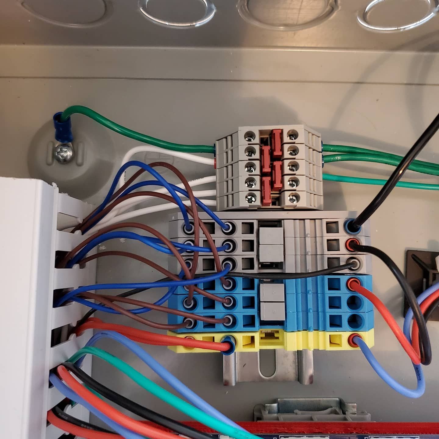
      • The Din Rails and din terminals for the high-voltage side I got on e-bay.
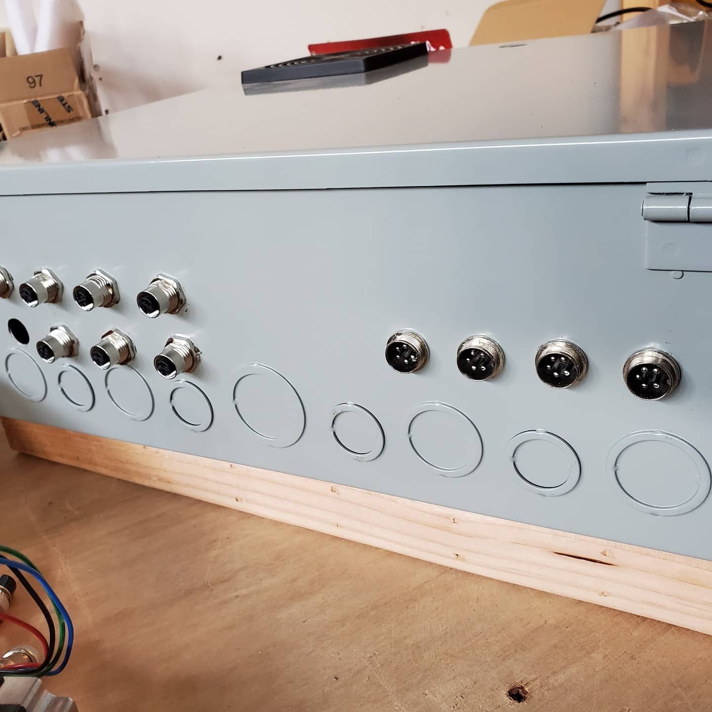
      • The Case is an 18" x 12" x 6" Hammond enclosure I got for like $40 including shipping from Wistix: https://www.wistexllc.com/enclosures/chko18126-18-x-12-x-6-hinged-cover-enclosure-with-knockouts.html
      • The Solid State Relays were around $30 each from Automation Direct.
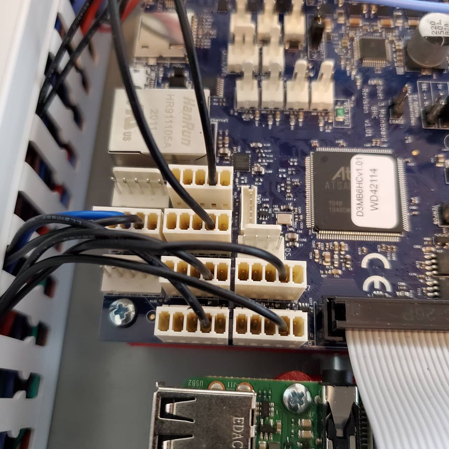
      • The small power supply and the low-voltage din rail components I got from Avid CNC. They are actually local here (I'm in the Seattle Area).
      • The RPI I got from Amazon.
      • I've got two different kinds of hookup wire (18g and 24g) From BNTECHGO (via Amazon). This stuff is fabulous. Real silicon sheath and very fine stranded. I bought boxes with 5 colors and 30' per color from Amazon. After stripping and crimping and routing this stuff, I'll never go back to cheap hookup wire.
      • The PVC wire channels are from e-bay.
      • I bought a metric drill bit set and a box of M6x4mm screws for the din-rail from McMaster-Carr along with the 3-tap sets for M3 and M6.

      If you have questions about something specific I haven't covered the just ask and I'll share what I can find/remember.

      posted in CNC
      N7JTIundefined
      N7JTI
    • N7JTI CNC Pendant Build

      As part of my CNC Build I also built one of the CNC Pendants. It seems like a nice design overall. However, I did make a few changes. I love that evertying is open-source so I can tinker and share. But first, some pictures:

      20201123_181550 (3).jpg

      20201123_181653 (2).jpg

      20201123_181946.jpg

      The build is nearly the same as the official link, but I substituted out the microcontroller for a Black Pill. This is an STM32F411 chip. There is full Arduino support (and micro-python, and native C/C++ support as well).

      I had to make some minor changes to the firmware. The changes fell into two categories. The first was updating all the inputs to match my build here. The 2nd was to fix the definition of a single class to remove the word "override" as it somehow prevented the build when using the stmduino libraries. My fork of the code-base can be found on my github here:

      • https://github.com/n7jti/CNC-Pendant-Firmware.

      The readme has the updated wiring and all the working changes to the code for the firmware. There are still lots of open IO ports on the board. I may even add some additional buttons to the pendant later.

      As for the BOM, I got he parts from ali-epxress:

      • The Pendant: https://www.aliexpress.com/item/32949106761.html
      • The microcontroller: https://www.aliexpress.com/item/4000068998794.html (STM32F411CUE)

      The choice of microcontroller simplified the design as the STM32 controller is a 3v3 Device but its inputs are 5v tolerant. The board takes the 5v in for power and tolerates the 5v GPIO inputs, but it sends out its own logic levels for the serial port at 3v3. So no need for the voltage divider on the output back to the board. And as you can see, even with the programming header installed, the board fits very nicely in the pendant.

      I'm still in the middle of my build so I haven't had it connected to the CNC machine yet. but I was able to do all of my testing by hooking up the output to a USB to serial converter: https://www.adafruit.com/product/3309. And I'd highly recommend using this method for testing as you can read the g-code commands directly in your serial terminal. Very handy!

      posted in CNC
      N7JTIundefined
      N7JTI
    • N7JTI Duet3 CNC Build

      I'm putting together a CNC machine based on a Duet3 and Raspberry Pi 4 for the controller and an Avid CNC Benchtop 2'x3' for the mechanical parts.

      I've got all the bits together to finish the control box, which I'm going to do this week. The mechanical parts come in two weeks. I don't know if there is any interest, but I'm going to sort of post about my progress on this thread as I go.

      I've completed the high-voltage side of the control box. I have two power supplies providing 3 different power rails. The large supply provides 24v at 600watts for the steppers. And the second smaller supply provides 12v for the endstop sensors and a 5v rail at 4a to power the rpi and the Duet3. Both are Meanwell power supplies. I've got the High Voltage on the right, and the low voltage on the left. I've done the first smoke test and I've got good 5v and 12v rails so next I will build the cables to power the external 5v line on the Duet3. When that is done I'll be able to use a 5v out to trip the first 3v relay and power on the 24v power supply so I can test that. I'll post again when I've gotten that far. Here is a picture the wiring progress so far.

      The DIN rails and wiring channels are held in place with M6 bolts that are drilled and tapped in to the back of the box itself. The Duet and the RPI are both mounted on DIN rail as well using a 3D printed mounting adapter that is screwed to a PCB din rail mount. Works great so far, and it lets air move underneath. I've got all the holes already cut in the box so I just need to get things wired.

      20201122_160239.jpg

      posted in CNC
      N7JTIundefined
      N7JTI
    • RE: N7JTI Duet3 CNC Build

      I had some nice progress today.

      I got the power supplies connected. I was double checking the connections from the schematic and I found this PS_ON pin on the external 5v power supply. This pin is pulled to ground as the result of an M80 command. I connected a lead from the 5v rail to the + side of my Solid State Relay on the High Voltage side of my 24v power supply, and the - side to the PS_ON pin. It worked!. I measured the current draw in the SSR at 14ma. I was thrilled to find this because I had originally planned to use an IO port for this and now I get to save an IO port. The other two relays (for the router, and the dust collection) will run from the 24v outputs, since I need lots of IO for the 6 endstops, the z-probe, and my CNC pendant.

      After the power was sorted out I got the four Nema 23 motors hooked up and setup in the config.g file. The motors worked first time!

      I had a little trouble talking with the Duet3 to start with, but then I found that I needed to remove the SD card if I was using it in SBC mode.

      IMG_20201123_122856_547.jpg

      posted in CNC
      N7JTIundefined
      N7JTI
    • RE: N7JTI Duet3 CNC Build

      I am now waiting on some more parts to continue the CNC build, but just to keep things moving along I posted information about my CNC Pendant build in a separate topic.

      posted in CNC
      N7JTIundefined
      N7JTI
    • RE: N7JTI Duet3 CNC Build

      Well, the M12 connectors for the end-stops came in so I wired them into the controller. The mechanical parts are due next week so that is still coming. Meanwhile, here are pictures of wiring in the endstops.

      The M12 endstop connectors are on the left. I'm still waiting for the last connector for the CNC Pendant. I used aircraft connectors for the 4 motor connectors on the right.

      IMG_20201203_124242_582.jpg

      One of the parts aviailable from Avid CNC was a DIN rail mounted kit to connect the endstops. The blue wires into the grey DIN rail is my ground, and the brown wires into the blue DIN connectors are my 12v rail. The off yellow one is my 5v rail, my common earth ground are the smaller grey DIN rail above. I don't know if there are standards for these. If so, I'm probably not following them. But I did want my box to be "finger safe" so everything is crimped and in connectors with no exposed voltage wires.

      IMG_20201203_124242_584.jpg

      The signal wires are black, and I've put them into the "IN" lines for IO3-IO8. I'll update the config.g on my github with the new configuration soon.

      IMG_20201203_124242_581.jpg

      The CNC machine has both high and low enstsops on the x and y axes, but the DUET seems to treat endstops as being only part of the homing. I'll probably set up some kind of "stop if the endstops ever get triggerd" trigger when not homing, but I'll set that up later.

      posted in CNC
      N7JTIundefined
      N7JTI
    • RE: N7JTI Duet3 CNC Build

      The mechanical parts came from Avid CNC on Tuesday and I spent a few nights putting them together.

      20201208_170842.jpg

      The kit had a lot of screws and bolts but it was all there and seems to be fairly well machined and square right out of the box.

      20201208_191625.jpg

      It isn't their "top of the line" machine but I think it will more than meet my needs as I learn how to use it.

      20201208_224052.jpg

      And of course, I figure I saved more than $1K by doing my own cables, motors, and control hardware (which is based on the Duet 3).

      20201211_131430.jpg

      I got the axes going in the right direction. I got the endstops configured. I have the homing macro's well written so that the global machine coordinates are repeatable.

      IMG_20201211_152649_426.jpg

      Now I'm here trying to figure out how to program the macro's to use the fancy "corner-finding" z-touch plate that I bought with the system. But I'll post my questions on that in another thread!

      Still now sawdust/chips yet. But I'm hoping to do that tomorrow!

      posted in CNC
      N7JTIundefined
      N7JTI
    • RE: N7JTI Duet3 CNC Build

      I got the parts in to connect the pendant, and I got the box mounted. I also got the endstops programed to halt if the machine hits the endstops, but it stills homes. The parts on the deck are to mill the dust shoe.

      The updates for the config have been uploaded to github: https://github.com/n7jti/duet3-avid-cnc

      plendant.jpg

      posted in CNC
      N7JTIundefined
      N7JTI
    • RE: Firmware Skips a few gcode instructions -- known issue?

      Ok, the machine seems to be performing mostly correctly now. I'm still seeing my macro probing the wrong direction occasionally, but I haven't caught it doing that in the last half-our. So I'm going to mark this as "solved" since my problem of the head occasionally not lifting seems to be fixed by the updated firmware.

      If I can find a clear pattern for when the probing macro probes "towards the workpiece" in the wrong direction I'll open another question.

      Thanks again for the great support!

      posted in CNC
      N7JTIundefined
      N7JTI
    • RE: N7JTI Duet3 CNC Build

      @alpenprinter So sorry it has taken me so long to get back to this.

      • Yes, I'm a Fusion360 user.
      • I use a version of the DIY CNC Fusion 360 CAM post processor: https://github.com/guffy1234/mpcnc_posts_processor
      • The software DOES create the M3 and M5 commands.
      • I do 3D probing using a probe block that I bought from Avid.

      If you are looking for the code or configuration that I use for my z-probe then you can have a look at my github repo where I store my configuration: https://github.com/n7jti/duet3-avid-cnc

      Sorry I'm so late in getting this info back to you. I hope you find it at least interesting if not actually helpful.

      posted in CNC
      N7JTIundefined
      N7JTI

    Latest posts made by N7JTI

    • RE: Setup Relay-Controlled Spindle

      @n7jti The "L" made no difference at all.

      posted in CNC
      N7JTIundefined
      N7JTI
    • RE: Setup Relay-Controlled Spindle

      @nightowl999 I can already switch my router on and off via a relay. The problem here is that I have to hand-edit the g-code that comes out of the post-processor in order to get my router to turn on and off automatically. That is painful. I'd rather have the router respond to M3/M5.

      So how do we get a pin to be high/low in response to an M3/M5 command?

      posted in CNC
      N7JTIundefined
      N7JTI
    • RE: Setup Relay-Controlled Spindle

      @o_lampe I tried using nil as a pin and it errors when I try it. SO I'm using an unused pin. I'll give the "L" a shot

      posted in CNC
      N7JTIundefined
      N7JTI
    • RE: Setup Relay-Controlled Spindle

      Is there some better place on the forum to post this?

      posted in CNC
      N7JTIundefined
      N7JTI
    • Setup Relay-Controlled Spindle

      I'm trying to get M3/M5 to work for spindle control on my Duet3 controlled CNC. I have a relay that controls power to my trimmer-router based spindle. There is no RPM control, just on-off.

      I can control the relay... If I just define it as a GPIO I can toggle the GPIO. So, this works to define the GPIO

      M950 P1 C"out1"
      

      The following code does NOT work to define a spindle. I get no errors, and I can't see a spindle defined in the web interface and M3 does not actuate the relay. out3 is not used.

      ; Set CNC mode
      M950 R0 C"out3+out1" Q100
      M563 P0 S"Spindle 1" R0 ; Create tool 0 with spindle 0 and call it "Spindle 1"
      M453
      

      What am I missing here?

      Thanks,
      Alan

      posted in CNC
      N7JTIundefined
      N7JTI
    • RE: N7JTI Duet3 CNC Build

      @alpenprinter So sorry it has taken me so long to get back to this.

      • Yes, I'm a Fusion360 user.
      • I use a version of the DIY CNC Fusion 360 CAM post processor: https://github.com/guffy1234/mpcnc_posts_processor
      • The software DOES create the M3 and M5 commands.
      • I do 3D probing using a probe block that I bought from Avid.

      If you are looking for the code or configuration that I use for my z-probe then you can have a look at my github repo where I store my configuration: https://github.com/n7jti/duet3-avid-cnc

      Sorry I'm so late in getting this info back to you. I hope you find it at least interesting if not actually helpful.

      posted in CNC
      N7JTIundefined
      N7JTI
    • RE: Firmware Skips a few gcode instructions -- known issue?

      Ok, the machine seems to be performing mostly correctly now. I'm still seeing my macro probing the wrong direction occasionally, but I haven't caught it doing that in the last half-our. So I'm going to mark this as "solved" since my problem of the head occasionally not lifting seems to be fixed by the updated firmware.

      If I can find a clear pattern for when the probing macro probes "towards the workpiece" in the wrong direction I'll open another question.

      Thanks again for the great support!

      posted in CNC
      N7JTIundefined
      N7JTI
    • RE: Firmware Skips a few gcode instructions -- known issue?

      Ok, so here's the problem I've got with G30. It probes the bed and sets the machine coordinates.

      That isn't helpful. I need the WCS coordinates to be updated to z0.

      posted in CNC
      N7JTIundefined
      N7JTI
    • RE: Firmware Skips a few gcode instructions -- known issue?

      Ok, I think I may have found it. The dive height I set negative becase it was probing the wrong direction... that seemed to have unintended consequences. So it is no longer diving after touching the plate.
      ...

      posted in CNC
      N7JTIundefined
      N7JTI
    • RE: Firmware Skips a few gcode instructions -- known issue?

      @Phaedrux but the problem I seem to be having with BOTH of these is that the directions are very backwards. instead of lifting on a g30 contact it is diving. And instead of probing DOWN towards the touchplate with the G38 command it is probing UP.

      Does the beta firmware probing not pay attention to which direction is positive on my z-axis? This used to work.

      posted in CNC
      N7JTIundefined
      N7JTI