Oh, I see. I thought the graph represented the bed and the empty strip on the left of the graph made me thing something was wrong. Thanks for the explanation.
Best posts made by agrapa
-
RE: G29 bed mesh leaving a large area unprobedposted in Tuning and tweaking
Latest posts made by agrapa
-
RE: G29 bed mesh leaving a large area unprobedposted in Tuning and tweaking
@droftarts Not sure if it would make sense, but have the grid drawing represent the bed? For instance: in Prusa Slicer I see a grid with the exact size of the bed, and every square represents 10mmx10mm. It makes it very easy to plan multiple prints or to position a large print correctly on the bed.
-
RE: G29 bed mesh leaving a large area unprobedposted in Tuning and tweaking
Indeed, now it is perfect, thanks a lot!
-
RE: G29 bed mesh leaving a large area unprobedposted in Tuning and tweaking
@Phaedrux said in G29 bed mesh leaving a large area unprobed:
Your M557 is asking to probe at X185, which it cannot reach, so it skips it
perfect explanation, thanks a lot!
-
RE: G29 bed mesh leaving a large area unprobedposted in Tuning and tweaking
Oh, I see. I thought the graph represented the bed and the empty strip on the left of the graph made me thing something was wrong. Thanks for the explanation.
-
RE: G29 bed mesh leaving a large area unprobedposted in Tuning and tweaking
Also, why would it have a warning that says "Skipping grid point (185.0, 80.0) because Z probe cannot reach it" if I can use the "machine control" button labelled "X+100" to make the nozzle reach X=197 ?
-
RE: G29 bed mesh leaving a large area unprobedposted in Tuning and tweaking
Thanks for your help so far. What I expect it to do:
I think it is normal that there is a 34.6mm empty strip on the right because the probe cannot physically reach there.
The graph circle positions could represent the position of the nozzle or the position of the probe. My expectation in each case would be:
1-If the circles represent the probe, then there should not be a strip on the left, as the probe can reach that side.
2-If the circles represent the nozzle, then there should not be a strip on the right, as the nozzle can reach it fine, and while it is there, it can probe. A second expectation in this case is that the z-correction should apply when the nozzle visits the probed point, which is not where the nozzle was when it was probed. For instance, if at probe time, the probe is at (1,10) and the nozzle is at (35.6,4.15) and it finds the z to be 0.5mm, then at print time, when the nozzle visits (1,10), the z-correction should be applied. Note this is not when the probe revisits the same point that was probed, but when the nozzle visits the point that was probed.
-
RE: G29 bed mesh leaving a large area unprobedposted in Tuning and tweaking
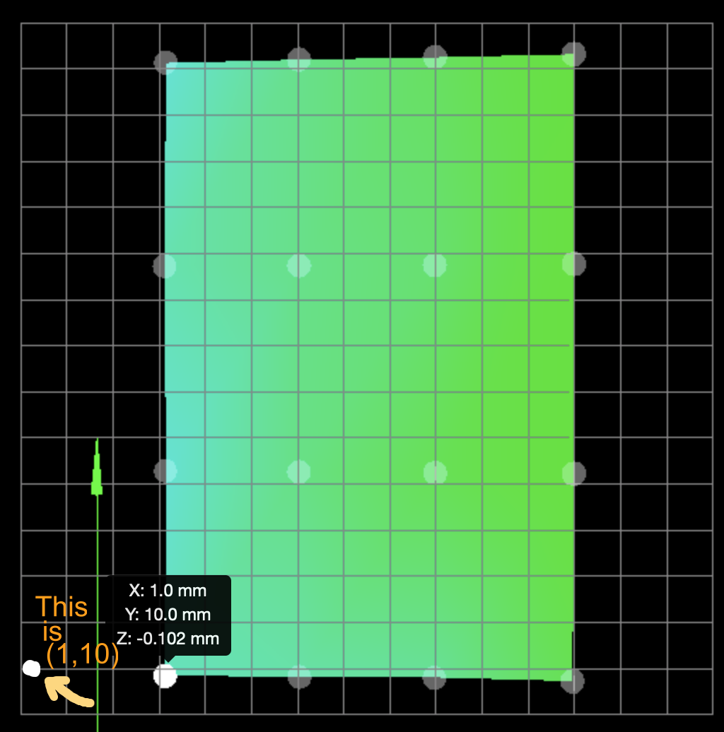
This is the first probe point with M557 X1:185 Y10:220 P5:4

Not easy to see, but if you look closely, the BLTouch arm is deployed and touching close to the 0,0 corner, while the left nozzle is further to the right. The right nozzle is actually not screwed into its heat block in the pic. -
RE: G29 bed mesh leaving a large area unprobedposted in Tuning and tweaking
Thanks for your help Phaedrux.
I tried M557 X-33.6:161.4 Y6:220 P5:4 but that caused the first probe position to be at a point where the nozzle is over the bed, but the probe is not (pic below):
What I meant by drawing at the position of the nozzle is what we see in the graph above. If we were drawing the positions actually probed (the position of the probe), it would look like this:
-
RE: G29 bed mesh leaving a large area unprobedposted in Tuning and tweaking
Phaedrux: the nozzle can go from (0,0) to (197,231). The probe can travel the same distance but offset by -34.6,5.85, so from (-35.6,5.85) to (161.4,236.85)
-
RE: G29 bed mesh leaving a large area unprobedposted in Tuning and tweaking
I forgot to mention: the nozzle's minimum X is 0, but the probe can go to -34.6