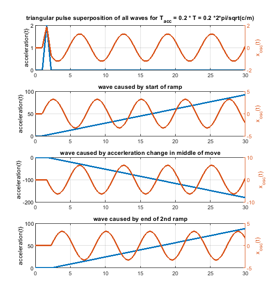
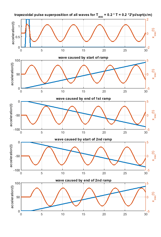
Some input from my side - i am also surprised, but a triangular speed change doesn't seem to improve ringing at all times compared to a rectangular one. I would be glad if somebody finds a mistake below
1. What happens in between a speed change ?
For a mass spring system like m * xdotdot +c * x = c * y(t) with y(t) as a step or ramp follows:
the position over time equals for a step wise change of y(t)
x(t) = (k_step * t^2)/2 - (k_step * m)/c + (k_step * m * cos((c^(1/2) * t)/m^(1/2)))/c
and for a ramp wise change of y(t)
x(t) = (k_ramp * t^3)/6 + (k_ramp * m^(3/2) * sin((c^(1/2) * t)/m^(1/2)))/c^(3/2) - (k_ramp * m * t)/c
k_step is the step size/acceleration [m/s^2] and k_ramp the ramp rate [m/s^3].
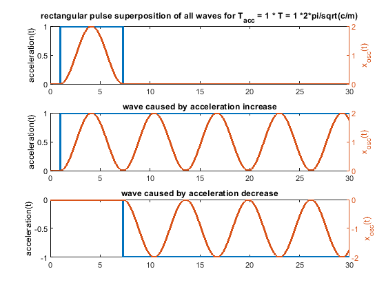
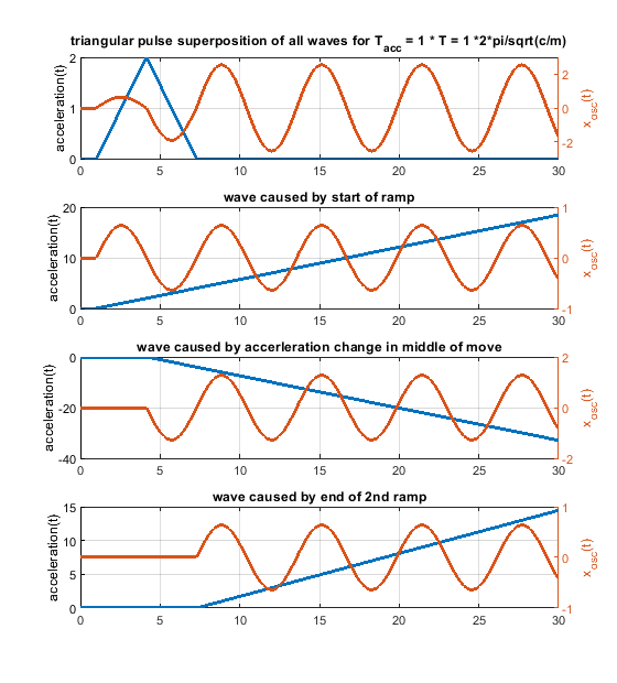
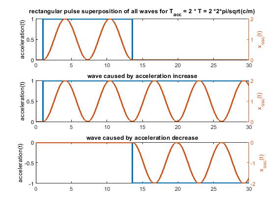
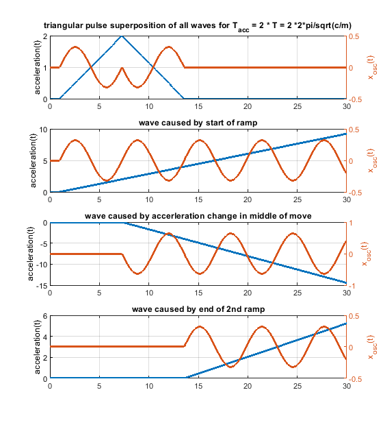
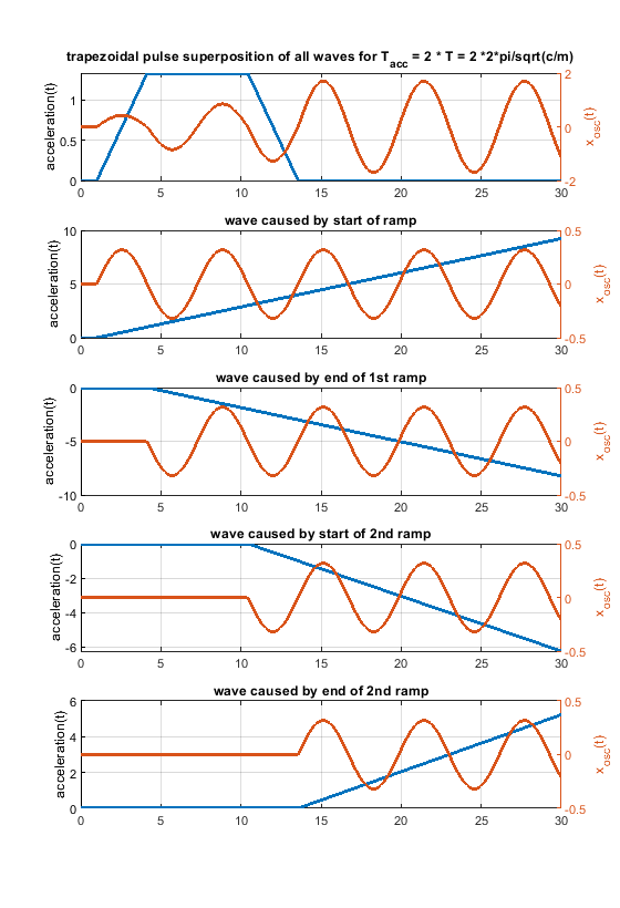
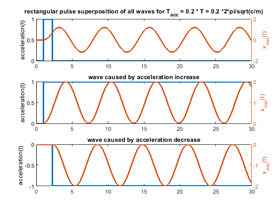
So every change of the acceleration causes a wave. Many acceleration changes causes many waves and these waves get superpositioned, that means they are just summed up. A rectangular acceleration profile consists of 2 stepwise changes of the acceleration - it produces 2 waves, which interfere. A triangular one creates 3 waves, because 3 ramp wise changes are needed.
The amplitude of the possible oscillations (ringing) is defined by k_step * m/c in the step case and k_ramp * sqrt(m)^(3/2)/c^(3/2). This is just the amplitude of a single wave, not the superposition of many waves.
Which method (ramp or step) does produces bigger waves ?
Dividing k_ramp * sqrt(m)^(3/2)/c^(3/2) by k_step * m/c leads to k_ramp/k_step * sqrt(m/c). By that the ratio of the amplitudes is a function of c/m.
The frequency doesn´t change, it is defined by the system itself - not by the applied motion profile.
If the speed has to be the same after the same time for a rectangular shaped acceleration change as for an triangular shaped one of a certain pulse width, k_ramp equals to 4 * k_step/pulse_width. Substituting this k_ramp into k_ramp/k_step * sqrt(m/c) gives amplitude_ramp/amplitude_step = 4 * sqrt(m/c) / pulse_width.
So depending on sqrt(m/c) and the pulse width, the oscillations during the speed change can be higher or smaller, comparing a rectangular or triangular shaped acceleration change profile. BTW sqrt(c/m)/2/pi is the natural frequency and 2 * pi * sqrt(m/c) the period time T.
In other words, if the pulse width is bigger than 2 * T/pi a single ramp produces smaller waves than a single step, used in a rectangular or triangular profile.
The natural frequencies f of the most important parts (steppers, belts, tubes) of my stiff/fast 3d printer are in the range of 300 - 70 Hz, or periods of 0.003 to 0.015 s. They can oscillate alone at their own natural frequency or all together with frequencies close to the smallest frequency. My slow printer is about factor 10-50 "slower" and less stiff. If damping is increased, these frequencies get smaller.
I use printing accelerations > 1g on my fast printer, so if the acceleration takes 0.01 s (pulse width) with 1g, the speed increases by > 100 mm/s.
In this case amplitude_ramp/amplitude_step = 2 * T/pi/pulse_width --> 2 * 0.003/pi/0.01 = 0.19 and 2 * 0.015/pi/0.01 = 0.96. So the fast parts gets 0.19 times less excited by the ramp, the slow parts not really.
If the speed change would be only 25 mm/s, it would only take 0.0025 s and by that a triangular acceleration profile would generate bigger waves compared to a rectangular one. Because in the middle of the triangular shape we need a "double" sized ramp rate change to flip the sign of the acceleration change, the triangular shaped change can be even worse .
On my slow printer c/m is much smaller, but also the used acceleration, so in total it also ends up, that triangular can be better but doesn´t have to. To make it even more complex, depending on the various parts (steppers, belts, tubes etc.) and their different natural frequencies, it can be that the steppers would need a triangular shaped acceleration change and the belts a rectangular....
In case the pulse width equals to the period time T, "amplitude triangular / amplitude rectangular = 2/pi". That means the produced single waves comparing a single step with a single ramp, will be by a factor of 0.64 smaller in the ramp case
2. What does a fourier spectrum of a triangular pulse and rectangular pulse show ?
It just shows the amplitudes after applying the total speed change. It doesn´t show what happens during the speed change. Above equations show it.
The Fourier transform of the rectangular and triangular change show which frequencies gets excited by the rectangular and triangle acceleration profile. If the fourier shows the amplitude is zero for e.g. all frequencies with multiples of period T, these frequencies doesn't get excited by the speed change as a whole. If this is the natural frequency of the mass spring damper system sqrt(c/m)/2/pi, it means the total oscillation of the total speed change will be zero. It doesn't mean, that there are no oscillations happening during the speed change. Only the superposition of all waves together is zero.
Because we talk about ringing, for pure x/y/z printers we don't see ringing during the speed change in our prints, we see it after the speed change has been done. But for all others (deltas scaras, Hs, etc.) the ringing during the speed change will also create artifacts.
Damping (which is significant) is also not included. Therefore the zero amplitude positions are just not there - at least by far not perfectly.
The fourier spectrum also doesn't compare the maximum total deviation of the target and actual trajectory, it just compares the amplitudes. This is ok, as long as we only compare ringing. To compare dimensional accuracy, this would be wrong.
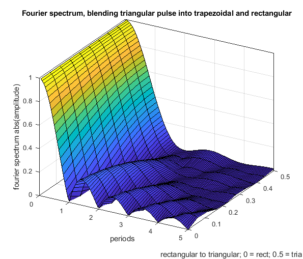
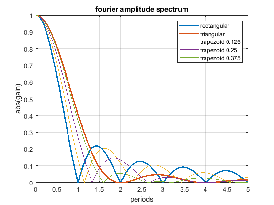
The fourier spectrum shows:
- The rectangular acceleration change has cancellation positions at multiples of T.
- The triangular acceleration change has cancellation positions at multiples of 2 * T.
- Above 1.29 * T the triangular shape is - excluding all of the above written - better as the rectangular shape and vice versa.
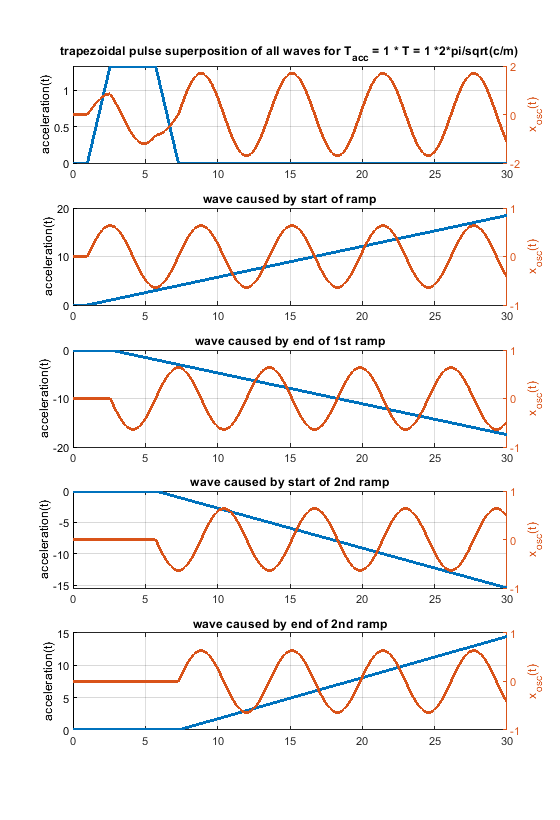
- A triangular shape can be blended into a rectangular one, using a trapezoidal shape (but that doesn't mean that all, that all possible shapes are included in this comparison).
- Close to zero (< 0.2 T), there is not significant difference between different profiles - that is our normal operating position.
- The rectangular change excites higher frequencies much more than the triangular one, this is because of the sharp edges of the step.
- Using different trapezoid shapes, it is possible to generate cancellation locations “everywhere” between the rectangular and triangular profile.
The following Fourier spectrum compares different acceleration profiles, which all have the same pulse width and same end speed.
Another figure to show how a rectangular change can be blended into a triangular one using a trapezoidal shape.
