3. How to utilize the cancellation points ?
From the Fourier transform we know, we could have no ringing after (that doesn't mean not in between) a speed change. To be able to use the zero amplitude positions to cancel the total ringing of a complete speed change, we have to know the period time which is 2 * pi/sqrt(c/m). Unfortunately c/m is by far not constant and not only one c/m has to dominate. It will vary among different fdm printers by a factor of up to 100 and it will vary also during a print. E.g. on a prusa style printer with a moving bed, the mass as well as the stiffness changes significantly. For the 1st layer c/m is big and for the last layer e.g. 200 mm above the bed with 500 g printed c/m will be very small, depending on the shape of the print, it might vary arbitrarily. On ultimaker style printer the same is valid, in a corner the stiffness is max and in the middle min. If the stepper current is doubled, c/m of the stepper is doubled. If the current of the stepper drops at high velocities, c/m of the stepper follows.... so c/m is not constant and in addition there is more than 1 mass spring damper system acting !
So in total the length of a speed change would have to be adjusted during the print - to hunt the cancelation points. I don´t claim that this couldn´t be done (in theory), but for e.g prusa printers it won´t be doable or only in certain cases. On ultimaker style printers it will "only" work near e.g. the middle of the bed and as long the stepper current doesnt drop to much due to speed.
In my case my stiff printer has (stepper, belts and tubes) c/m values in the range of 1e5 to 1e6 [N * kg/m]. My slow printer has c/m values about 1e3 to 1e4 [N * kg/m].
A c/m of 1e6 gives a period time T of 2 * pi/sqrt(1e6) = 63ms (or 160 Hz); a c/m of 1e3 gives 199 ms or 5 Hz.
My stiff printer uses printing accelerations > 1g, so in 63 ms the speed change after one period time T of acceleration is > 10.000 * 0.063 = 630 mm/s. With 0.2 g at my slow printer the speed change would be 2000 * 0.2 = 400 mm/s. In other words the nowadays used acceleration settings just "mirrow" c/m and the time used for acceleration when printing is between 0 and << 0.1 - 0.2 * T. The fourier transform doesn´t show a significant difference there between different moveplan profiles - but the amplitudes of the waves generated during the move differ.
So if we would print using speeds like before, we would have to reduce the acceleration to catch the 1st wave cancelation point at 1 * T. Increasing the acceleration time will amplify extrusion problems. In addition i don´t want to print slower....
If we would hunt for the 1st wave cancelation point by increasing the max speed, we would get really high speeds, with the need for "max. acceleration as a function of speed" and a working pressure advance.
In case we ask for multiple speed changes (moveplan) and not for a single speed change, the cancelation possibility gets more interesting. Multiple speed changes in a row can stimulate much lower frequencies as a single speed change. So we know that normally a single speed change operates at e.g. << 0.2 T. But multiple speed changes together could easily stimulate at or above 1 T. The high level move planner would have to adjust the move plan in a way, that the speed changes itself act close to the cancelation points. This could be beneficial for a lot of small moves in a row. E.g. when printing top and bottom layers and it fills a gap by zigzag moves.
4. Is a triangular profile a good choice to compare s-curve acceleration with a rectangular change ?
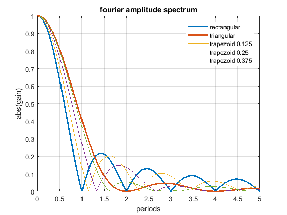
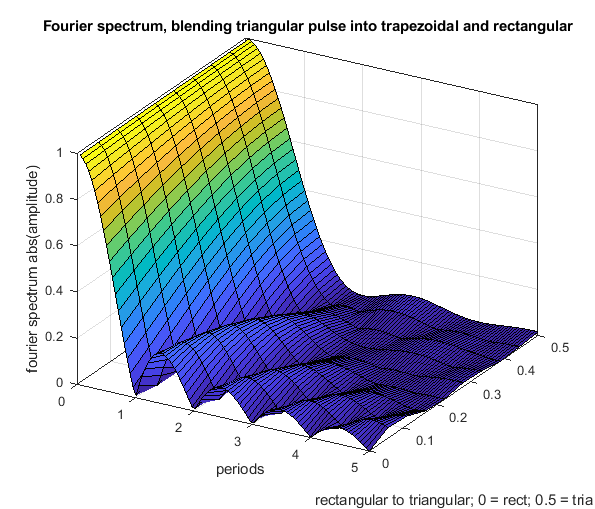
In addition to above, yes and no. It is true that one can blend the fourier transform from a triangle over a trapezoid into a rectangle (see the figure below). But whos says that we have to limit it to that simple kind of shapes ?
Just try the following: instead of one triangular shape apply 2 after each other. Both have the half width of the single one and same amplitude. By that the frequency spectrum is shifted to the left by T/2 and the 1st wave cancelation is also at 1 * T, like in the rectangular case (and not like 2 * T in the single triangular case). So comparing a triangular with a rectangular profile just compares two profiles and not all available possibilities.
5. The main fdm problem is extrusion - not ringing.
Ringing can be solved by proper engineering. Extrusion is thermodynamically and fluid wise limited - these limits "cannot" be changed - at least not much. Pressure advance would help a lot, if it would have a chance to work. With a stepwise acceleration change, it can only work under certain limiting conditions. With “s-curve” (a more gentle) acceleration the pressure advance jerk problem caused by the step wise acceleration change would be "wiped away". Pressure advance could show its potential.
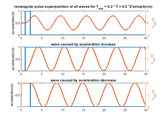
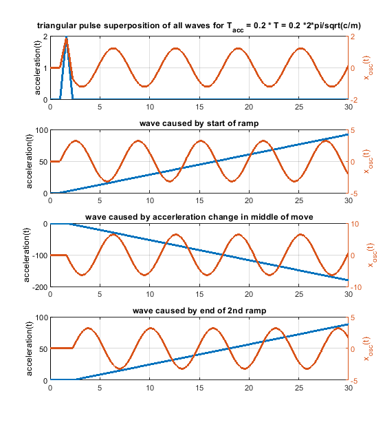
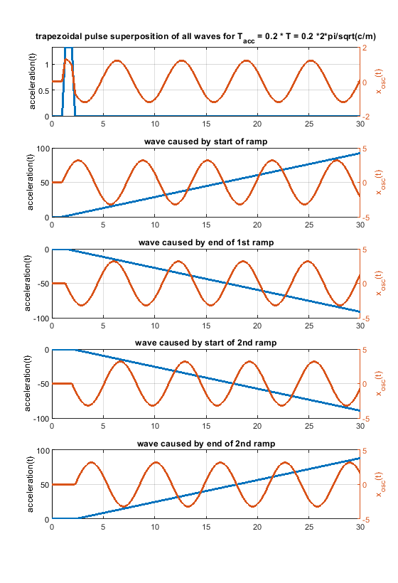
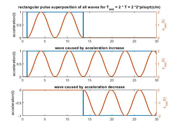
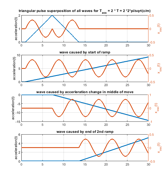
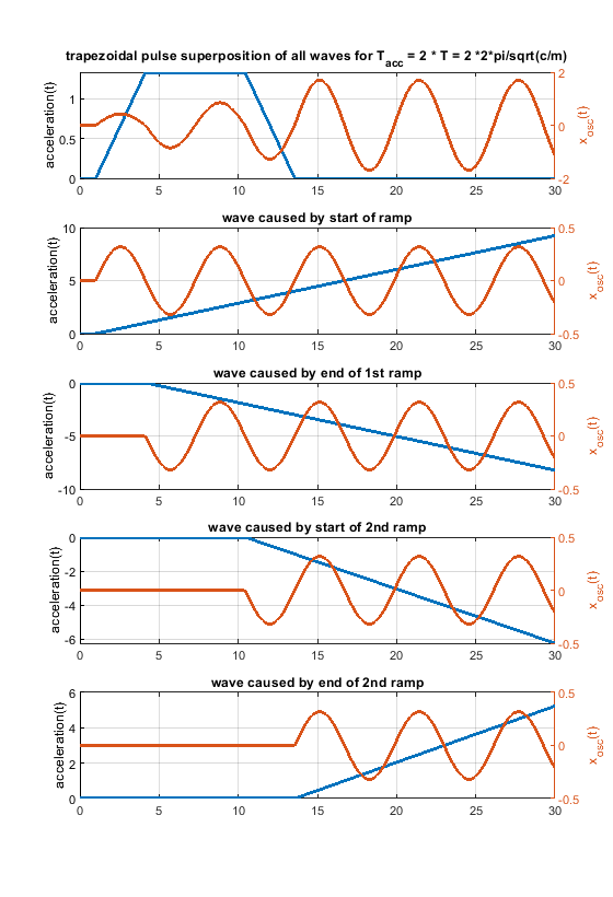
6. Because one picture says more than 1000 words, i have attached some figs for a system like m * xdotdot +c * x = c * y(t) (so no damping and only one spring mass system). m = c = 1.
In case the acceleration time equals to the time period T, as shown in the fourier transform, the whole rectangular acceleration change produces no remaining waves (only without damping, with damping like in real life this doesn´t work perfectly at all). The triangular as well as trapezoidal acceleration change show waves - which would be damped quickly including damping, but this is the ringing we see on pure x/y/z printers.
Blue is the acceleration change ydotdot(t), orange is only the oscillation part of x(t).
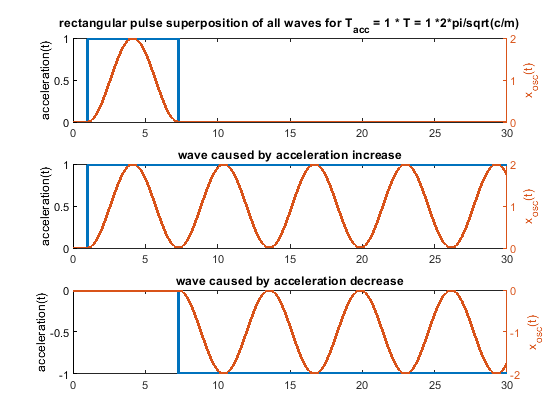
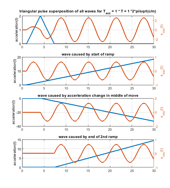
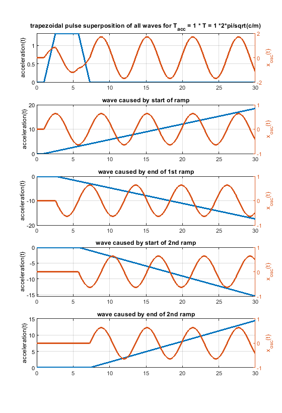
Same for acceleration time equals to the time period T * 2 - now the triangluar change also produces no remaining waves. If instead of one triangle of width "a" 2 triangles of width "a/2" and the same height would be applied, the triangular profiless also would also show no remaining waves at 1 * T - like the rectangular case.
The same for a pulse width of 0.2 T. In real life it looks much better, because damping acts.
