Duet3D Logo Duet3D
    • Tags
    • Documentation
    • Order
    • Register
    • Login
    1. Home
    2. vp
    • Profile
    • Following 0
    • Followers 1
    • Topics 17
    • Posts 73
    • Best 5
    • Controversial 0
    • Groups 0

    vp

    @vp

    5
    Reputation
    10
    Profile views
    73
    Posts
    1
    Followers
    0
    Following
    Joined Last Online

    vp Unfollow Follow

    Best posts made by vp

    • Stepper driver dead (caused by multimeter ?)

      Hi,

      i have/had a brand new Duet Wifi and managed to kill the D4 stepper driver.

      I was connecting the steppers to the crimp connectors and to the Duet wifi and when testing, i forgot that one of the 4 cables to the stepper was still connected to a multimeter. The multimeter was operating in "beep" mode, that means if the probes of the multimeter touch each other (or there are connected) it makes "beep".
      One probe was connected to one of the 4 stepper cables and the other was connected to air - so no connection to what ever.

      Anyhow, this was the only cause i could find why D4 stopped working, M122 D4 shows now a temperature shut down due to overheating/short to ground.
      The D4 TMC stepper driver has now a very small surface hole/mark, about 0.5 mm in diameter (which the others don´t have, i think it wasn´t there before) - i guess this was created when D4 died.

      I have a Duex5, so i can live with one driver less, but the D4 is going ******* hot….. even with no stepper connected.

      So i have some questions:

      1. Can this driver failure really be caused by the multimeter - or do i have another problem? BTW Duet Wifi was working for about 2 weeks and i was finishing the cabling to its final state - so it worked before.

      2. Because D4 is ******* hot now, can i just desolder the TMC2660?

      3. Which TMC2660 do i have to order as a replacement - are there any special issues?

      Thanks in advance!

      posted in Duet Hardware and wiring
      vpundefined
      vp
    • RE: Backlash compensation

      @dc42:

      Why not use either anti-backlash nuts, or a finer pitch on the Z leadscrews so that the backlash is tiny, or a less fine pitch so that gravity does the work? Bed compensation already adds a lot of wear to the Z leadscrews, and doing backlash compensation will increase the wear further. Even better, use a flat bed.

      The whole story is about - why should somebody spend > +100-200 EUR in addition (cheap vs. expensive rails, ball screws and nuts) when the problem could be solved easily in firmware ? Why does the firmware support bed mesh leveling ? Why skewness correction, why xy scaling ? ….

      Wear appears also without backlash compensation. So the question is also, when do you have to replace the ballscrews and nuts ?
      Anti backlash nuts increase the wear always, not only during bed leveling.

      Could you please explain why backlash compensation by adding a delta distance to the move would increase wear ? Backlash occurs because there is no force transmitted - so how should it wear significantly when the ball screw is just rotation additionally in the region where "no force" is transferred ?

      In addition, I don´t care about wear as long as i am able to compensate it ! On a cartesian printer it is anyhow only needed for bed mesh leveling - i don´t see the point regarding additional wear because of backlash compensation - there is no significant wear in addition and not to forget all also expensive screws wear out and the question is when do i have to replace them. Without "wear compensation" much sooner.

      Printers are getting bigger and bigger, my bed is lightweight and > 400 x 400 mm and even with hiwin rails (which i use on my CNC mill) i would not be sure that the bed would "float" with gravity. On my 150 *150 printer i don´t need mesh bed leveling, but show me how you level a 400 x 400 mm bed to +-0.02 mm (which is already quite fuzzy for a 0.1 mm perfect 1st layer) which is heated up to 80 °C.

      I am sorry DC42 but i dont get the point why z backlash compensation should be worse than any other "firmware compensation". As always the standard user wont use 100 % of all features, but especially bigger printers need mesh bed leveling to utilize thier potential and again ballscrews and nuts wear out. If a firmware change could elongate the life cycle of the screws and nuts it would help everybody.

      posted in Tuning and tweaking
      vpundefined
      vp
    • RE: Acceleration as a function of speed

      I did choose WANTAI 42BYGHW811, in my setup, they should be able to achieve nearly 1g close to about 1500mm/s, without losing 1/16 micro step with a light direct driven extruder/hot end. I don´t have a "problem" at 160mm/s, this is just an example to show that if the torque drop starts with 12 V at "0" rps, this problem is existing in the normal operating range of 3D printer, just check the curves.

      1. In 3D printers we normally run the motors well below their maximum current, because at maximum current the motors get very hot. At reduced current, the back emf due to inductance is lower, so the (reduced) torque is maintained to higher speeds. For example, if you halve the current, then the torque at low speeds will be half what is shown on the torque/speed curves and will be almost flat until it intercepts the torque/speed curve shown for the same motor and same driver voltage at full current.

      This is not special for 3d printing, it is a good rule of thumb for every stepper application to use at max about 80 % of the specified amps. The steppers itself are normally rated to > 100°C surface temperature, I operate my steppers at about 80 % of the rated current and they get at max about 50 °C (also NEMA32s), which is at least for me no problem. Because P = IIR it is for sure sensitive to the chosen current - but it is also no trick to cool them and in the long term i will use mine at maybe > 100 % current.

      Who operates his steppers at half of the design current? This 50 % comparison is completely misleading and even at 50 % and 12 V there is also before 5rps a torque drop. If somebody operates at 50 % i would suggest him to go for different (smaller and faster) steppers. But do these people buy a premium product like the Duet Wifi ?

      2. Because we want precise motion during printing, we use 1/16 or greater microstepping, and to get position accuracy this means that the motors need to have far more holding torque than is needed to produce the acceleration demanded, so that we can maintain a position accuracy of around one 1/16 microstep. But high-speed travel moves don't need this accuracy during the high speed part of the motion, it's only the end of the move that needs to be accurate. So quite a large loss of torque is acceptable during the middle part of a travel move. If you know the mass of the print head or bed or whatever the motor is moving, you can work out the torque needed to produce the desired acceleration, and you just need to make sure the motor can provide this torque with a sufficient safety margin e.g. 2x.

      Yes, that is one reason for the firmware change request, now we get back on track.

      But i would say we don´t use 16 microsteps for finer resolution (with a 16 T GT2 pulley 16th means in theory 0.01 mm), because this fine steps never happen with this accuracy (e.g. stepper nonlinearities and all other mechanical errors of a 3D printer are much bigger) we just do it because it runs smoother and less noisy - and because it doesn´t cost anything. Maybe it can reduce some fancy patterns on deltas, but there only relative accuracy is needed. On xyz printers 16th stepping doesn´t improve accuracy at all.

      I have to show more clearly what this request is for because it still seems to be not clear:

      1. Many speed as well quality problems are extrusion related. Often people claim their E3D v6 cannot go above e.g. 50 mm/s because then under extrusion and so on is happening. They say the extrusion capacity is not enough - which is wrong. The problem is, that the hot end print speed varies and by that the extrusion rate. Unfortunately, molten plastics have a viscoelastic material law which brings the time factor in play. So any change in extrusion rate/speed is going to make problems - but this is not the root cause. The root cause is the varying printing speed. The root cause for the varying printing speed is a lack of useable acceleration which is limited by the mass/stiffness of the system and the stepper torque which is a function of speed .

      Especially at lower layer heights and small nozzles or with e.g. a volcano, the extrusion capacity is enough for speeds far above 100 mm/s. But as soon as the speed drops the extrusion problems will occur. On youtube are enough videos showing damn fast prints - with a miserable print quality. I want fast prints with good quality - this is not possible without the maximum acceleration.

      2. Many problems are retraction related. Why do we need retraction at all ? Because too much plastic would ooze out. The smartest way I know to overcome this problem is to give the oozing process no time. Half the time and you half the amount which could ooze out. If you print flexible material that is the only way to go. If you don´t need to retract (or less), problems of 1. are also reduced. Solve the problem by just increasing the speed of travel moves.

      3. Think the other way round. With a Duet Wifi capable of acceleration as a function of speed, one could use smaller (faster) and cheaper steppers. This could mean one uses NEMA14 for normal printers or NEMA 17 instead of NEMA23 for big size printers.

      4. printing time
      Many prints need excessive amounts of travel moves. Normally most travel moves are short distance moves. Using a histogram to show the distribution of travel move length, it would be very heavy on the left side (much more short than long moves). What does short distance mean ? With 2g it takes 25 mm to reach 1000 mm/s, with 5g 10 mm. The problem is, that long travel moves need more time and increasing max travel speed would reduce the time significant. To increase max travel speed, i would have to reduce the max torque - also in the low speed region were most of the moves happen. Increasing max travel speed ends up to give no benefit, if the max torque on the low side has to be decreased.

      A higher acceleration in the low-speed region (printing) means a higher average printing speed and again a reduction of printing time.

      5. Jerk. Jerk was introduces to get away from blobs on every corner (bleeding edges) and to decrease printing time. Unfortunately jerk is the most brutal way and is mostly based on backlash and low stiffness. In the old days both was existing at much higher levels than nowadays. Using too much jerk shows ringing/resonance artifacts in the print (as well as too high accelerations). Using 2 g it takes 0.0xyz mm to get to e.g. 20 mm/s. But it is much more gentle and gives by that less artifacts - or at same amount of artifacts much more printing speed. Jerk could be reduced to nearby 0 and substituted by "soft" acceleration. Doing so would be like a poor mans s-curve acceleration in the very low speed region.

      6. Future developments like s-curve acceleration/moves. Although some people thinks it is too CPU intensive, for me it is clear that in future we will use something like s-curve like moves. This gives much more possible printing speed at same artifact level. But using s-curve like moves reduces at the same max acceleration the average acceleration - so in total the benefit is much smaller as it cold be. To overcome this problem, acceleration has to be really maximized - according speed.

      Finally:
      I don´t care at all, what people are doing now, i question for what is possible, i want to push the limits - and premium products like the Duet are bought because the "normal" stuff is not as good as it could be. It is not true that printing speed is limited by extrusion rate to e.g. 100 mm/s. It is limited by too much varying printing speed, caused by too low acceleration settings.
      Why should we bottleneck our printers? Why should we waste resources?
      I don´t care if I am able to use 5g in the low-speed region (<= 1000 mm/s) already now if I can get 8g…. or travel with 2000 mm/s instead of 1000 mm/s.

      BTW: On travel moves, the deflection of the printer parts doesn´t matter (nearby). When printing they become very significant at higher accelerations (e.g. > 1g), and more stiffness (a stiffer system means more mass) doesn´t help more. So finally the firmware will also have to address this problem because there is a mechanical material limit where engineering cannot increase the stiffness vs weight ratio anymore (see 6.).

      [Edit: i added 5 and 6]

      posted in Firmware wishlist
      vpundefined
      vp
    • RE: Backlash compensation

      …CNC milling/router machines use a lot of ballscrews and backlash is well known there and much more a problem

      But what is the problem ? I would not "jerk", i just would correct the target end position of a move. If the direction changes, the target end position of the move has to be adjusted by a value - what is the problem to do that (at least for CNC mills etc.)?

      On 3D-printers the E-move has to stay the same (or to shift a little bit), even when the "move plan distance" gets longer or shorter. And to be honest even hiwin or TBI screws don´t have 0.00 mm backlash under load.

      All the mechanical "solutions" doesn´t work perfectly and have their own issues (e.g. more wear, less netto torque...).

      On my 3D-printer i stopped using the auto mesh bed leveling, because even < 0.05 mm backlash is too much to make it better with auto bed mesh leveling than without. Loading the nuts so heavily, that there is no backlash, just wears them off unnecessarily (i don´t do that just for the 1st layer) ....

      If hysteresis at least in z could be compensated, i would use auto bed leveling again.
      People also could use cheaper hardware, because the software would compensate it, one reason more to buy a Duet - or not to buy it.

      At least for auto bed leveling we need it also in 3D printing.

      posted in Tuning and tweaking
      vpundefined
      vp
    • New hybrid (old and new) moveplan ?

      There is a long ongoing discussion about new moveplans here: https://forum.duet3d.com/topic/4802/6th-order-jerk-controlled-motion-planning/72
      The above thread is already very long and focuses on the "nth zero order jerk" possibilities - which is in my opinion suboptimal for fdm. Therefore i started a new thread.

      What has to be considered concerning a fdm moveplan

      • 3D printing doesn´t profit from nth order zero jerk stuff, we just need to ensure a 1st order continuous derivative of the acceleration. Fdm is extrusion driven and the task is not to dynamically balance the water level of a moving glass. Because the hot end acts like a low pass filter, everytime the extrusion rate (speed) changes, the real extrusion rate will deviate from the target extrusion rate. Therefore the task is to provide an as constant as possible extrusion rate which means constant speed (the average speed should be constant, no long acceleration phases). Speed profiles where the acceleration is always <> 0, are extrusions wise suboptimal, they add unnecessary extrusion errors.

      • The steppers can only provide a certain power, which in the end decreases with speed. Because of power = force * velocity = mass * acceleration * velocity --> if the power is constant, the max possible acceleration has to drop with 1/v. This gets more and more important when moving at higher speeds (e.g. > 150 mm/s), because there the stepper power falls off significantly - but we would need more. The same is valid for setting the jerk value.

      • Jerk is in principle an adjustable feature and not a bug - it has to remain. If somebody doesn´t like it, he should be able to set it to (at least nearby) zero. But using zero jerk in fdm will add additional problems/limitations.

      • Ringing only occurs when braking (at the end of a move) and not when the speed increases! In order to keep the average speed constant we need short acceleration phases, that means high accelerations, therefore it is suboptimal not to accelerate as fast as possible at the start of the move.

      • Ringing is not only influenced by the move profile, it is also influenced by the torque stiffness of the stepper, especially for stiff and light printers

      • Users need the possibility to tune the profile to their special needs (e.g. FDM is different to CNC carving, a Cartesian is different to a delta....) - so we need tuning factors.

      I would like to discuss an alternative (a hybrid of old and new) moveplan:
      It is a 2 step approach.

      1. compute the moveplan as usual to determine v_start, v_end and the total time it takes per ramp
      2. spread the ramping steps over time by adjusting the time for each step using a correcting factor to "bend" the straight speed profile to the desired shape

      ad 2.
      The old speed profile for a single speed ramp is given by:
      a_old = constant

      This leads to:
      v_old = v0 +a_oldt
      s_old = (a_old
      t^2)/2 + v0t
      dt_step_old = s_step/(v0 + a_old
      t)

      v0... velocity at start of the ramp
      v_end... velocity at end of the ramp
      a_old... acceleration (constant)

      s_step... distance one step (or e.g. 1/16 step) takes
      dt_step_old... time one step (or e.g. 1/16 step) takes
      t... time, counted from start of the ramp

      NEW speed profile for a single ramp (others are also possible)
      a_new = K0 + K1t + K2t^pf
      v_new = v0 + K0t + (K1t^2)/2 + (2K2tt^pf)/(pf^2 + 3pf + 2) + (K2pft^(pf - 1)t^2)/(pf^2 + 3pf + 2)
      s_new = tv0 + (K0t^2)/2 + (K1t^3)/6 + (K2t^pft^2)/(pf^2 + 3pf + 2)

      K0, K1, K2, and pf are constants (tuning factors) which are defined by the following conditions

      We e.g. assume the new moveplan will need exactly the same time to finish the ramp as when moving according to the old moveplan. So the average speed is the same. This will also lead to nice comparable figures.

      Option A: Acceleration at start a_start and end of the ramp a_end shall be 0 and pf = 2 (2 is a special case, a_max will always be a_old * 1.5 and the profile is symmetrical):
      This leads to

      K1 = 0
      K2 = -6a_old^2/(v0 - v_end)
      K3 = -6
      a_old^3/(v0 - v_end)^2

      bzw.
      a_new = - 6a_old^2t /(v0 - v_end) - 6a_old^3t^2/(v0 - v_end)^2
      v_new = v0 +K1t^2/2 +K2t^3/3 = v0 - 3a_old^2t^2/(v0 - v_end) - 2a_old^3t^3/(v0 - v_end)^2
      s_new = v0t +K1t^3/6 +K2t^4/12 = tv0 - a_old^2t^3/(v0 - v_end) - a_old^3t^4/(2*(v0 - v_end)^2)

      The question is now, how we have to spread the steps over time, to get the desired shape. So finally we compare dt_step vs dt_step_old to get a correction factor for the "step timer".

      dt_step = s_step/(a_old^2t^2/(v0 - v_end) + 2a_old*t + v0)

      That means all we have to do is to multiply the time for one ramping step calculated with the old move plan dt_step_old with this correcting factor:

      cf_dt_step = dt_step/dt_step_old =
      (v0 + a_oldt)/((K2t^3)/3 + (K1t^2)/2 + K0t + v0) = (v0 + a_oldt)/(a_old^2t^2/(v0 - v_end) + 2a_oldt + v0)

      Or we could just compute the dt_step directly like above - that means 1st compute the moveplan, as usual, to define v_start, v_end and the total duration for each ramp and 2nd, once this is known, just time the steps according to dt_step. The correcting factor has only to be computed once for the limiting axis - not for every axis ! But for sure it has to be applied to all axes. Instead of using a correcting factor, it would be optimal to adjust the "timer base clock" according to the correcting factor - that might be complicated.

      In the end what comes out looks like shown below.
      v is the velocity, a is the acceleration and cf the correcting factor. Because the new moveplan doesn´t change anything before or after the ramp, we don´t need to care about it and it is not shown.

      0_1530381101303_1_v_a_cf_1.png

      Option B: Because we know, that we cannot accelerate as fast at high speed as at low speed, we set pf to 0.5. Now it looks like shown below. The longer the move takes, the higher is the speed and the lower the acting acceleration. Because we know the maximum speed of the move from the 1st step (old move profile), we can set the pf factor accordingly. When the speed increases pf has to be < 2 and when the speed decreases pf has to be > 2.

      0_1530381189801_2_v_a_cf.png

      Option C : Because ringing only occur when braking, there is no need to accelerate as gentle when braking. We also know from state of the art, that a stepwise change of the acceleration works in principle. Therefore we should set a_start and a_end > 0 and a_start >> a_end. This leads to lower maximum acceleration and lower acceleration at higher speeds - that is what we want. But we also see in the figure below, that the profiles change only a little bit - so the potential of using a_start and a_end <> 0 is not too big.

      For this general case the constants are
      K0 = a_start
      K1 = 2a_old(a_end - a_old - a_oldpf + a_startpf)/((v0 - v_end)(pf - 1))
      K2 = (pf + 1)
      (a_end - 2a_old + a_start)/((-(v0 - v_end)/a_old)^pf(pf - 1))

      0_1530381260019_3_v_a_cf.png

      The figure below compares A, B & C regarding the used acceleration vs speed. Because of the open loop stepper limitations, the acceleration has to be significantly smaller with increasing speed. Otherwise, we don´t utilize our equipment at lower speeds or we run into problems at higher speeds. As shown pf = 0.5 vs. 2.0 does a much better job. Using a_start and a_end > 0 does also help a bit.

      0_1530381288196_4_a_v.png

      posted in Firmware wishlist moveplan jerk acceleration extrusion
      vpundefined
      vp

    Latest posts made by vp

    • RE: S-Curve/ sinusoidal , Jerk +acceleration

      3. How to utilize the cancellation points ?
      From the Fourier transform we know, we could have no ringing after (that doesn't mean not in between) a speed change. To be able to use the zero amplitude positions to cancel the total ringing of a complete speed change, we have to know the period time which is 2 * pi/sqrt(c/m). Unfortunately c/m is by far not constant and not only one c/m has to dominate. It will vary among different fdm printers by a factor of up to 100 and it will vary also during a print. E.g. on a prusa style printer with a moving bed, the mass as well as the stiffness changes significantly. For the 1st layer c/m is big and for the last layer e.g. 200 mm above the bed with 500 g printed c/m will be very small, depending on the shape of the print, it might vary arbitrarily. On ultimaker style printer the same is valid, in a corner the stiffness is max and in the middle min. If the stepper current is doubled, c/m of the stepper is doubled. If the current of the stepper drops at high velocities, c/m of the stepper follows.... so c/m is not constant and in addition there is more than 1 mass spring damper system acting !

      So in total the length of a speed change would have to be adjusted during the print - to hunt the cancelation points. I don´t claim that this couldn´t be done (in theory), but for e.g prusa printers it won´t be doable or only in certain cases. On ultimaker style printers it will "only" work near e.g. the middle of the bed and as long the stepper current doesnt drop to much due to speed.

      In my case my stiff printer has (stepper, belts and tubes) c/m values in the range of 1e5 to 1e6 [N * kg/m]. My slow printer has c/m values about 1e3 to 1e4 [N * kg/m].

      A c/m of 1e6 gives a period time T of 2 * pi/sqrt(1e6) = 63ms (or 160 Hz); a c/m of 1e3 gives 199 ms or 5 Hz.
      My stiff printer uses printing accelerations > 1g, so in 63 ms the speed change after one period time T of acceleration is > 10.000 * 0.063 = 630 mm/s. With 0.2 g at my slow printer the speed change would be 2000 * 0.2 = 400 mm/s. In other words the nowadays used acceleration settings just "mirrow" c/m and the time used for acceleration when printing is between 0 and << 0.1 - 0.2 * T. The fourier transform doesn´t show a significant difference there between different moveplan profiles - but the amplitudes of the waves generated during the move differ.

      So if we would print using speeds like before, we would have to reduce the acceleration to catch the 1st wave cancelation point at 1 * T. Increasing the acceleration time will amplify extrusion problems. In addition i don´t want to print slower....

      If we would hunt for the 1st wave cancelation point by increasing the max speed, we would get really high speeds, with the need for "max. acceleration as a function of speed" and a working pressure advance.

      In case we ask for multiple speed changes (moveplan) and not for a single speed change, the cancelation possibility gets more interesting. Multiple speed changes in a row can stimulate much lower frequencies as a single speed change. So we know that normally a single speed change operates at e.g. << 0.2 T. But multiple speed changes together could easily stimulate at or above 1 T. The high level move planner would have to adjust the move plan in a way, that the speed changes itself act close to the cancelation points. This could be beneficial for a lot of small moves in a row. E.g. when printing top and bottom layers and it fills a gap by zigzag moves.

      4. Is a triangular profile a good choice to compare s-curve acceleration with a rectangular change ?
      In addition to above, yes and no. It is true that one can blend the fourier transform from a triangle over a trapezoid into a rectangle (see the figure below). But whos says that we have to limit it to that simple kind of shapes ?

      Just try the following: instead of one triangular shape apply 2 after each other. Both have the half width of the single one and same amplitude. By that the frequency spectrum is shifted to the left by T/2 and the 1st wave cancelation is also at 1 * T, like in the rectangular case (and not like 2 * T in the single triangular case). So comparing a triangular with a rectangular profile just compares two profiles and not all available possibilities.

      5. The main fdm problem is extrusion - not ringing.
      Ringing can be solved by proper engineering. Extrusion is thermodynamically and fluid wise limited - these limits "cannot" be changed - at least not much. Pressure advance would help a lot, if it would have a chance to work. With a stepwise acceleration change, it can only work under certain limiting conditions. With “s-curve” (a more gentle) acceleration the pressure advance jerk problem caused by the step wise acceleration change would be "wiped away". Pressure advance could show its potential.

      6. Because one picture says more than 1000 words, i have attached some figs for a system like m * xdotdot +c * x = c * y(t) (so no damping and only one spring mass system). m = c = 1.

      In case the acceleration time equals to the time period T, as shown in the fourier transform, the whole rectangular acceleration change produces no remaining waves (only without damping, with damping like in real life this doesn´t work perfectly at all). The triangular as well as trapezoidal acceleration change show waves - which would be damped quickly including damping, but this is the ringing we see on pure x/y/z printers.

      Blue is the acceleration change ydotdot(t), orange is only the oscillation part of x(t).

      0_1534912949791_rect_1T_way.png
      0_1534912997625_tria_1T_way.png
      0_1534913018215_trap_1T_way.png

      Same for acceleration time equals to the time period T * 2 - now the triangluar change also produces no remaining waves. If instead of one triangle of width "a" 2 triangles of width "a/2" and the same height would be applied, the triangular profiless also would also show no remaining waves at 1 * T - like the rectangular case.

      0_1534913042697_rect_2T_way.png
      0_1534913650179_tria_2T_way.png
      0_1534913094729_trap_2T_way.png

      The same for a pulse width of 0.2 T. In real life it looks much better, because damping acts.
      0_1534913131269_rect_02T_way.png
      0_1534913157250_tria_02T_way.png
      0_1534913172497_trap_02T_way.png

      posted in Firmware wishlist
      vpundefined
      vp
    • RE: S-Curve/ sinusoidal , Jerk +acceleration

      Some input from my side - i am also surprised, but a triangular speed change doesn't seem to improve ringing at all times compared to a rectangular one. I would be glad if somebody finds a mistake below

      1. What happens in between a speed change ?
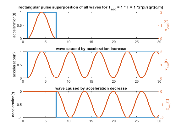
      For a mass spring system like m * xdotdot +c * x = c * y(t) with y(t) as a step or ramp follows:

      the position over time equals for a step wise change of y(t)

      x(t) = (k_step * t^2)/2 - (k_step * m)/c + (k_step * m * cos((c^(1/2) * t)/m^(1/2)))/c

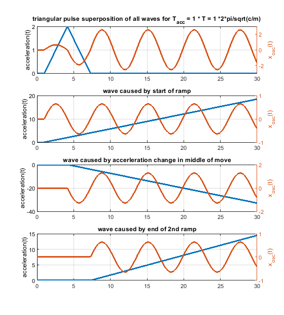
      and for a ramp wise change of y(t)

      x(t) = (k_ramp * t^3)/6 + (k_ramp * m^(3/2) * sin((c^(1/2) * t)/m^(1/2)))/c^(3/2) - (k_ramp * m * t)/c

      k_step is the step size/acceleration [m/s^2] and k_ramp the ramp rate [m/s^3].

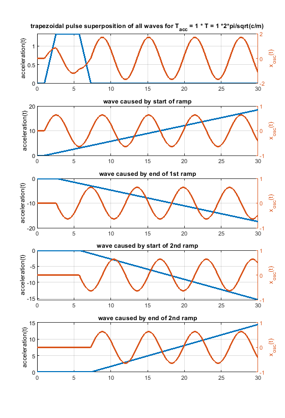
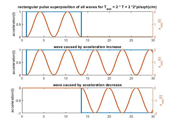
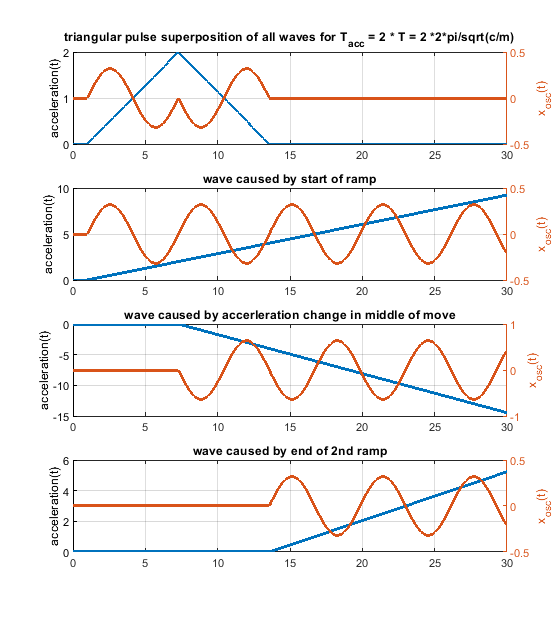
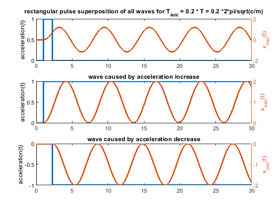
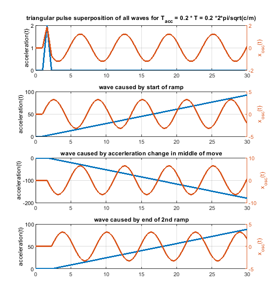
      So every change of the acceleration causes a wave. Many acceleration changes causes many waves and these waves get superpositioned, that means they are just summed up. A rectangular acceleration profile consists of 2 stepwise changes of the acceleration - it produces 2 waves, which interfere. A triangular one creates 3 waves, because 3 ramp wise changes are needed.

      The amplitude of the possible oscillations (ringing) is defined by k_step * m/c in the step case and k_ramp * sqrt(m)^(3/2)/c^(3/2). This is just the amplitude of a single wave, not the superposition of many waves.

      Which method (ramp or step) does produces bigger waves ?
      Dividing k_ramp * sqrt(m)^(3/2)/c^(3/2) by k_step * m/c leads to k_ramp/k_step * sqrt(m/c). By that the ratio of the amplitudes is a function of c/m.

      The frequency doesn´t change, it is defined by the system itself - not by the applied motion profile.

      If the speed has to be the same after the same time for a rectangular shaped acceleration change as for an triangular shaped one of a certain pulse width, k_ramp equals to 4 * k_step/pulse_width. Substituting this k_ramp into k_ramp/k_step * sqrt(m/c) gives amplitude_ramp/amplitude_step = 4 * sqrt(m/c) / pulse_width.

      So depending on sqrt(m/c) and the pulse width, the oscillations during the speed change can be higher or smaller, comparing a rectangular or triangular shaped acceleration change profile. BTW sqrt(c/m)/2/pi is the natural frequency and 2 * pi * sqrt(m/c) the period time T.
      In other words, if the pulse width is bigger than 2 * T/pi a single ramp produces smaller waves than a single step, used in a rectangular or triangular profile.

      The natural frequencies f of the most important parts (steppers, belts, tubes) of my stiff/fast 3d printer are in the range of 300 - 70 Hz, or periods of 0.003 to 0.015 s. They can oscillate alone at their own natural frequency or all together with frequencies close to the smallest frequency. My slow printer is about factor 10-50 "slower" and less stiff. If damping is increased, these frequencies get smaller.

      I use printing accelerations > 1g on my fast printer, so if the acceleration takes 0.01 s (pulse width) with 1g, the speed increases by > 100 mm/s.
      In this case amplitude_ramp/amplitude_step = 2 * T/pi/pulse_width --> 2 * 0.003/pi/0.01 = 0.19 and 2 * 0.015/pi/0.01 = 0.96. So the fast parts gets 0.19 times less excited by the ramp, the slow parts not really.

      If the speed change would be only 25 mm/s, it would only take 0.0025 s and by that a triangular acceleration profile would generate bigger waves compared to a rectangular one. Because in the middle of the triangular shape we need a "double" sized ramp rate change to flip the sign of the acceleration change, the triangular shaped change can be even worse .

      On my slow printer c/m is much smaller, but also the used acceleration, so in total it also ends up, that triangular can be better but doesn´t have to. To make it even more complex, depending on the various parts (steppers, belts, tubes etc.) and their different natural frequencies, it can be that the steppers would need a triangular shaped acceleration change and the belts a rectangular....

      In case the pulse width equals to the period time T, "amplitude triangular / amplitude rectangular = 2/pi". That means the produced single waves comparing a single step with a single ramp, will be by a factor of 0.64 smaller in the ramp case

      2. What does a fourier spectrum of a triangular pulse and rectangular pulse show ?
      It just shows the amplitudes after applying the total speed change. It doesn´t show what happens during the speed change. Above equations show it.
      The Fourier transform of the rectangular and triangular change show which frequencies gets excited by the rectangular and triangle acceleration profile. If the fourier shows the amplitude is zero for e.g. all frequencies with multiples of period T, these frequencies doesn't get excited by the speed change as a whole. If this is the natural frequency of the mass spring damper system sqrt(c/m)/2/pi, it means the total oscillation of the total speed change will be zero. It doesn't mean, that there are no oscillations happening during the speed change. Only the superposition of all waves together is zero.

      Because we talk about ringing, for pure x/y/z printers we don't see ringing during the speed change in our prints, we see it after the speed change has been done. But for all others (deltas scaras, Hs, etc.) the ringing during the speed change will also create artifacts.

      Damping (which is significant) is also not included. Therefore the zero amplitude positions are just not there - at least by far not perfectly.

      The fourier spectrum also doesn't compare the maximum total deviation of the target and actual trajectory, it just compares the amplitudes. This is ok, as long as we only compare ringing. To compare dimensional accuracy, this would be wrong.

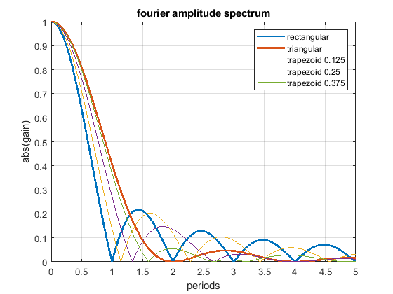
      The fourier spectrum shows:

      • The rectangular acceleration change has cancellation positions at multiples of T.
      • The triangular acceleration change has cancellation positions at multiples of 2 * T.
      • Above 1.29 * T the triangular shape is - excluding all of the above written - better as the rectangular shape and vice versa.
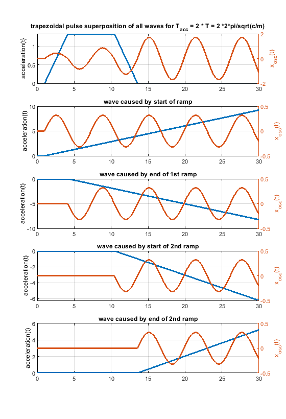
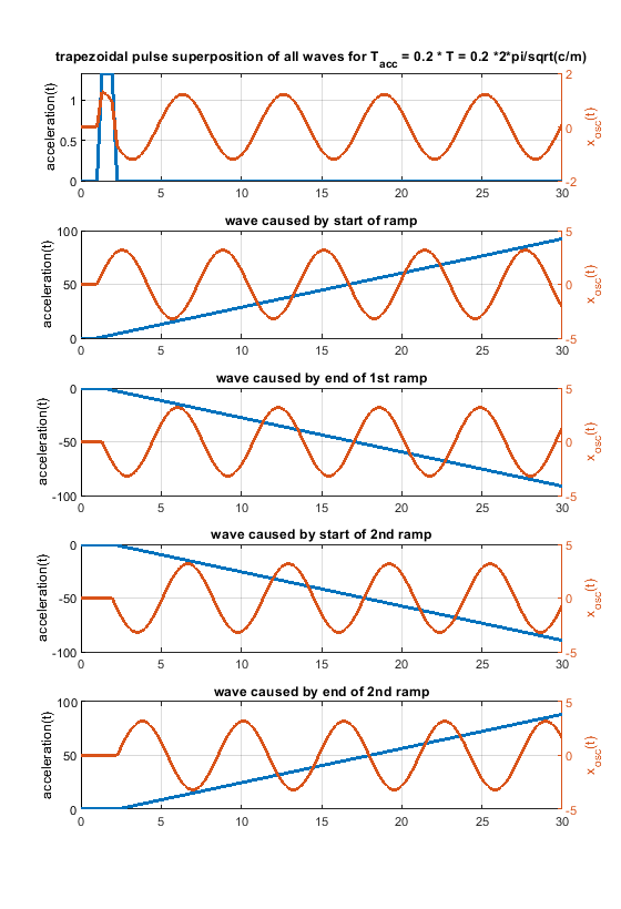
      • A triangular shape can be blended into a rectangular one, using a trapezoidal shape (but that doesn't mean that all, that all possible shapes are included in this comparison).
      • Close to zero (< 0.2 T), there is not significant difference between different profiles - that is our normal operating position.
      • The rectangular change excites higher frequencies much more than the triangular one, this is because of the sharp edges of the step.
      • Using different trapezoid shapes, it is possible to generate cancellation locations “everywhere” between the rectangular and triangular profile.

      The following Fourier spectrum compares different acceleration profiles, which all have the same pulse width and same end speed.
      0_1534912254367_FF_gains.png

      Another figure to show how a rectangular change can be blended into a triangular one using a trapezoidal shape.
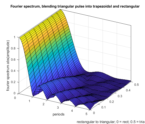
      0_1534913795799_FF_gains_2D.png

      posted in Firmware wishlist
      vpundefined
      vp
    • RE: S-Curve/ sinusoidal , Jerk +acceleration

      i can see the chart on my tablet, but not on my PC, something seems to block the url/domain on my PC. Thanks.

      Some well working theory/basics:
      Given a spring mass system with mass m and spring stiffness c and force excitation it follows:

      • If the acceleration (force) is changed stepwise by amount k1, the amplitude a1 of the oscillation caused by this step is directly proportional to the step size k1.

      • If the acceleration is changed like a ramp with ramp rate k2, the amplitude a2 of the oscillation caused by the ramp start is directly proportional to the ramp rate k2.

      It follows that a2 / a1 == k2 * sqrt(m / c) * k1. [EDIT: typo correction -> m/c corrected to sqrt(m/c)]

      So depending on the ramp rate (or step size) and also on m/c, the generated oscillation has a bigger or smaller amplitude for a step wise change or a ramp - it depends on the system (m & c) and tuning settings (k1 & k2).
      I didn´t include damping because with damping the results are by far not as obvious and beautiful - but in principle it is exactly the same. A real fdm printer is also a combination of mass/spring/damper systems, but one frequency will dominate (ringing) and the above is also still valid.

      The frequency (sqrt(stiffness/mass)) is naturally the same for ramp and step.

      So in case one big wave is generated (ramp start) compared to a lot of smaller waves (s-curve), it must be bad timing if the ringing is worse with s-curve OR it might come from a2 / a1 = k2 * sqrt(m / c) * k1.
      E.g. if one big wave is generated at acceleration start and the next bump/wave start follows at acceleration end with an unlucky phase shift, it will superposition and amplify (triangular s-curve). It is easy to add one big wave to another big wave, so that they amplify each other. But it is much harder to superposition many smaller amplitude varying waves (real s-curve) in a way that they amplify each other - which doesn´t mean it is not possible in principle.

      In the end the triangular acceleration profile might be an unlucky profile to compare s-curve with the step wise acceleration change !

      So depending on the above the ringing test results may vary. In general, many fdm printers will have comparable m/c and k2/k1 (k1 and k2 can be set anyhow). I didn´t check if this can be a game changer for some fdm printers. But there are very stiff and light (m/c is very small) as well as heavy and soft printers (m/c very high) out there....

      posted in Firmware wishlist
      vpundefined
      vp
    • RE: S-Curve/ sinusoidal , Jerk +acceleration

      @dc42: i cannot see any chart what do i do wrong ?

      below

      Here is a chart to compare how the two acceleration profiles excite ringing at different frequencies.

      is nothing (at least for me)

      posted in Firmware wishlist
      vpundefined
      vp
    • RE: S-Curve/ sinusoidal , Jerk +acceleration

      Hi, it is not too surprising that there is a certain time between the acceleration changes, which causes to increase or reduce ringing.

      Every time the acting force (acceleration) changes the system gets bumped and stars to oscillate. So every acceleration change introduces one oscillation and all oscillations together get super-positioned, meaning the waves can amplify or cancel each other. If the big bumps (ramp start and end) are spaced in time in a way the big waves overlap, the ringing will be maximized and vice versa. This effect will appear at multiple acceleration times (it is periodic).

      But it is surprising, that a more gentle change of acceleration will increase the problem anywhere. More gentle means less dominant waves and less chance of amplifying these dominant waves. Maybe it is just bad luck or a bad coincidence. At least in theory it seems hard to find a not too academic explanation for that behavior.

      Which s-curve profile did you use ? How big was the maximum acceleration using s-curve compared to the constant ramp acceleration ? How much was it higher ? Was the max speed or speed at the end the same ?

      What also should help to avoid amplifying interference is to use different acceleration changing shapes at start and end of a ramp. E.g. start with d(acceleration)/dt <> 0 and end with d(acceleration)/dt == 0.

      posted in Firmware wishlist
      vpundefined
      vp
    • RE: New hybrid (old and new) moveplan ?

      Hi RCarlyle,

      thanks for your comments, as with all longer threads it gets difficult to catch up.

      ad 1) I have described the problem, as short as possible writing above:
      The steppers can only provide a certain power, which in the end decreases with speed. Because of power = force * velocity = mass * acceleration * velocity --> if the power is constant, the max possible acceleration has to drop with 1/v. This gets more and more important when moving at higher speeds (e.g. > 150 mm/s), because there the stepper power falls off significantly - but we would need more.

      This is relevant for quick printers when printing and especially for travel moves. The problem as with nearby all new improvements is, that people have problems to stop thinking the old way. We should not care how things are done now, if we can do it better in future.

      You claim:
      More practically, if you actually run the numbers on nominal acceleration force demands versus motor torque capacity, most 3D printers have 10-50x torque safety factors

      1. What is your base/reference torque ? The given numbers are just not correct, for a somehow efficient printer, they are far too high and i assume you just judging by "how much torque is needed in theory to accelerate the inertias compared to not losing a 1/16th micro step". If one compares the needed torque at 1/16 micro stepping to accelerate with 0.1g at 100 % stepper current (nobody uses), it might look that way - but why should we bottleneck us artificially ? For sure, one can buy a Ferrari and limit the 500 kW engine to 50 kW - but why should we ? And would we buy a DUET ? For sure you could build a printer only using 1% of its possible torque - but we should make it as good and not as bad as possible.
        Yet, the only way to avoid ringing with "old school jerk" (without using low jerk values) is adding damping by friction. I use e.g. pre tensioned igus tribo tapes and if you measure the force needed to slide them and not losing 1/16th micro step, you will notice that there is no 10-50x factor at all. In the end increasing damping (and jerking the old way) gives more or less "junction deviation" results in terms of print quality.

      2. Also, we don´t talk only about fdm, tell a CNC guy that he has 10-50x more torque as he needs at higher speeds....

      3. There are not only printing moves. 1/16th micro doesn´t matter at all when traveling. Deltas may need to z-hop, but especially xy/z printers can utilize their full potential. The only way i know to avoid stringing with TPU/TPE etc. are damn fast travel moves. If you accelerate with 10g up to 400-500 mm/s, there is not much stringing left. But it would still decrease if i could use 20g and 1000 mm/s. Also, decreasing travel time can dramatically reduce printing time - depending on the model. These values are for my printer, but you can adjust them to any other printer.

      4. You talk about safety factors - i want to increase them when it is needed (at higher speeds) and not to choose them completely inefficient and still not having enough safety when we would need it.

      5. Don´t forget the new move plan. When the negative side of jerk is reduced, people will utilize this potential and use "the new jerk tuning parameter (junction deviation)" to increase speeds and accelerations. Not to forget, that the new move plan - if it should not slow down printing speed - needs to use higher acceleration values. By that everybody will dig dipper into the area where torque drops with speed although we would need more torque.

      6. People want G2/G3 - although as shown above - G2/G3 influences a very small percentage of the total printed filament length. If G2/G3 is included but not acceleration = f(speed), than this is not efficient at all.

      I did design my printer from the very beginning to be able to print at max. possible acceleration to get constant extrusion. My fine printing acceleration is 1g and for draft prints i use up to 5g. Travel moves are done with 10-20g. Because of travel moves i have to do gcode processing and split large moves into more segments with different allowed max speeds, or i have to limit the max. speed to avoid coming into the "torque drop zone".

      The problem nowadays is not to build a stiff printer, the problem is the hotend/extrusion part. Why should we artificially bottleneck us ?

      ad 2) Ringing only occurs when braking (at the end of a move) and not when the speed increases!
      I have written above:
      I assume, that as long as we don´t notice ringing, we don´t care about it.

      With the old move plan when increasing speed at the start of the ramp, when the acceleration is increased stepwise, this will generate a bump and oscillations - but these oscillations are in the "line of the path" (at least for cartesian printers). So all they do is to vary the amount of extrusion per length, which is compared to the overall extrusion error nothing.

      ad 3) With junction deviation coming there is no need to talk about that. But i disagree, in short terms, if what you say would be correct, all adaptive car suspension systems would not work;) In general the cheaper ones of these systems work only by adjusting the damping factor and not the spring stiffness, but it doesn´t matter how you reduce/increase the force at the right point in time as long as you adjust it properly.

      The point is to start with a lower spring stiffness (beginning jerk) and end with a higher spring stiffness (when oscillation would start) compared to normal. If you think in a step response way, the low stiffness at the beginning would lead to a later and slower crossing of set point and actual value. After crossing the set point value the overshoot would start and than (or just before) the spring stiffness is increased. This would lead to a bigger "junction deviation". Without reducing the stiffness at the beginning, the speed - when the overshoot occurs - would we much higher and by that the kinetic energy the system has to absorb also --> more ringing.
      Low stiffness at start (--> low speed when overshooting) and high stiffness at the end (nail it down) would definitely reduce the negative side of jerk. As you and i have written, the torque stiffness (stepper) is also only one part of the game. But the stiffer the printer, the more important it gets.

      The potential of the above is small and it is obsolete with the new move plan including junction deviation.

      posted in Firmware wishlist
      vpundefined
      vp
    • RE: New hybrid (old and new) moveplan ?

      @dc42 thanks for the sneak preview. Wow, that sounds like a lot of work and the need for a lot of ram and CPU ressources. Hope that works out stable and robust. Will this also work for UVWXYZ ?

      Junction deviation is the best "jerk" i know 😉

      If after the high level move planner the xyz moves are frozen, but not the stepper moves, how is it possible to limit speeds and accelerations of the steppers at non xyz printers (deltas, scaras etc.) ? In my opinion it is a must have to limit this to steppers and not to xyz moves. Otherwise on e.g. deltas this would bottleneck everything, because the worst case accelerations/speeds would have to be chosen as limit in the high level planner, by that not utilizing by a far amount the real possibilities. Limiting acc and speed to xyz moves just cares about the limitations of the "load" side (print head), but not about the possibilities of the "drive" side.

      Do you have any plans to adjust the maximum allowed acceleration according to speed ?

      In my opinion, using the old moveplan and spreading the moves over time, it could do the same and more, but with much lower efforts and need for ressources - which should be in general much more stable. If you allow a junction deviation, it "solves" the old jerk problem.

      Do you have any comments why spreading moves over time won´t work ?

      @JoergS5, i am sorry for confusing you, but i do not mean that a constant speed will be good for ringing. The extrusion would be as good as possible, if the extrusion rate (== speed) would never change. The hot end is like a low pass filter (spring damper system). It cannot follow quick changes. If the extruder stepper would produce e.g. a reasonable fast PWM signal, the nozzle would filter it and extrude a constant extrusion rate. Therefore any slow change in speed leads to a deviation between target and setpoint extrusion rate. Using high acceleration and jerk values gives in average a more constant speed profile and by that a more constant==better extrusion. This is why jerk was invented.

      Pressure advance takes care of the spring part and without filament slippage/missing steps and so on it indeed would help a lot. If the acceleration doesn´t jump anymore pressure advance will get much more valuable. So extrusion will get better with the new moveplan.

      I print a lot and for sure i did print also circles, but all you need to do is to save the stl with a high resolution.... you won´t be able to see a difference to a circle. If you use parts with changing curvature (which is normal using SolidWorks, Fusion, OnShape etc.) you need anyhow high resolution, G2/G3 won´t help you there...

      posted in Firmware wishlist
      vpundefined
      vp
    • RE: New hybrid (old and new) moveplan ?

      G2/G3 is only a small issue, i don´t want t spend too much time with it and most is already said.

      @T3P3Tony that is why i used fdm in brackets. CNC doesn´t use stls (that much). E.g. when milling a hole and using line segments the whole would become too small... but this can also be solved by using many line segments. Especially in the DIY environment and the DUET won´t be used for professional CNC milling.

      @wilriker thanks, what i miss in the discussion is the fact that G2/G3 can only be used for arc moves - that means perfect circles. Unfortunately there are not many perfect circles in a 3D print and the amount will drop in future more and more because nowadays CAD software is not limited to circles. You won´t find many real circles in many models because nowadays CAD software blend the curvature of different faces into each other.

      If a model contains a part of a sphere, this will always be sliced as a circle. But any other "circle" based object like cylinders and cones will only be sliced to circles if the orientation is perfect. That means the cross section base circle of a cylinder or cone has to line up perfectly with the x/y plane. If one rotates a standing cylinder by 1 degree, there are no circles in the x/y plane anymore. So in total, even if the final model was built up using some "circle" based features, it doesn´t mean at all, that after slicing there is only one single circle left. So why spend so much effort for something which effects maybe < 1-5% of the total printed filament length ? I think that the development resources can be used more efficiently - that doesn´t mean G2&G3 has no potential.

      Slic3r has been working on this for years. S3D had it in the very beginning and it was removed. So there is nothing new about it, the problems have not changed. A circle has to come from the model and not be interpolated afterwards, it will just create other artifacts and disk space is no real limitation. A stl doesn´t contain circles, that is why CNC doesn´t use stls (if it has to be accurate). If a slicer has to process the more intelligent file types (including curvature) everything is shifted to a complete different level.... maybe e.g. autodesk starts with it some when. People only think in one layer, but all layers together have to build up a 3D object. If the model is a mesh, that is easy to process and slice, but if the model is a 3D curvature this becomes a non linear optimization in at least 3 dimensions....

      posted in Firmware wishlist
      vpundefined
      vp
    • RE: New hybrid (old and new) moveplan ?

      ... the question is where do the G2 & G3 commands come from ? Before this is not solved and "everything" in fdm is based on stls, it doesn´t make sense (for me) to base something on G2 & G3 commands. There are good reasons why (fdm) slicers don´t provide G2 & G3 moves and that won´t change too soon. Or did i miss something ?

      posted in Firmware wishlist
      vpundefined
      vp
    • RE: New hybrid (old and new) moveplan ?

      I did the same for a move without constant speed phase, see below. I still don´t see the problem. The ramp up as well as the ramp down takes exactly the same time as the old moveplan - why should it get longer ?

      0_1530591925916_mp_new_pf_0 0_0 0_2 2_up_down.png

      The same for the end/start condition, that a_end of the up ramp and a_start of the down ramp equals exactly a_old (nobody would do that if s-shape moves are possible, but to show the method works without problems).

      0_1530592369949_mp_new_pf_0 0_0 0_2 2_up_down_sharp.png

      What´s the problem ?

      [EDIT: a [mm/s^2] in the figures is the absolute value of a]

      posted in Firmware wishlist
      vpundefined
      vp