Duet3D Logo Duet3D
    • Tags
    • Documentation
    • Order
    • Register
    • Login
    1. Home
    2. Manuel207
    • Profile
    • Following 1
    • Followers 0
    • Topics 1
    • Posts 6
    • Best 0
    • Controversial 0
    • Groups 0

    Manuel207

    @Manuel207

    0
    Reputation
    1
    Profile views
    6
    Posts
    0
    Followers
    1
    Following
    Joined Last Online

    Manuel207 Unfollow Follow

    Latest posts made by Manuel207

    • RE: Printing ovals instead of circles

      @deckingman I tested a 400mm move and it is nearly perfect (maybe 0,2-0,3mm if even measurable?).

      I also printed the same part with the second tool and voila perfect circles. So you are on the right path. It has probably something to do with the external driver. I am going to test different microstep settings and currents on the external driver? Do you have other suggestions what it could cause?

      posted in Tuning and tweaking
      Manuel207undefined
      Manuel207
    • RE: Printing ovals instead of circles

      @deckingman I have different values because I have different external motor drivers. Drive 5-7 driving the z-axis and drive 8 the x-axis. Since i ran out of onboard drivers on my duet wifi I used the drivers i had laying around. The project grew over time. When I started the build I was on a budged. Nowadays I would switch to a Duet 3 board.
      I need the higher values for the DM542T to work properly. Lower values caused wierd layershifting to one side.

      Good point with the microstepping per axis, I corrected this thank you!
      The x-axis is not listed because I set microstepping via dip-switches on the external motor drives. (With this in mind I can delete the z-axis microsteps too)

      The different steps/mm values for x and u also refer to using different motor drivers. U is driven by the onboard duet wifi driver and x by the external DM542T.
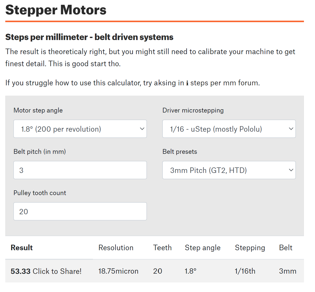
      I am running a HTD 3M 10mm belt on the y axis with a 20 teeth pulley.
      The calculator gave me this value:

      Screenshot 2024-01-07 124122.png

      The measured dimensions of the parts are correct. Is there better way to measure the driven distance directly on the axis?

      Thanks for the tip with the colon seperator I updated my config file!

      The currents for x and z in M906 are also not specified beacuse i am driving them of the external driver.

      posted in Tuning and tweaking
      Manuel207undefined
      Manuel207
    • RE: Printing ovals instead of circles

      @mendenmh The ovals are 45 degrees to x&y, good point.
      It's a rectilinear cartesian motion system. Printhead is on xy (uy). Y-axis runs on two individual steppers, each has its own limit switch.
      I could try to play with the skew compensation, but the current measurements work to produce rectangular parts.

      posted in Tuning and tweaking
      Manuel207undefined
      Manuel207
    • RE: Printing ovals instead of circles

      @Phaedrux I tried to see if the skew compensation has an effect on the dimensions of the ovals. But the result is exactly the same with and without.

      posted in Tuning and tweaking
      Manuel207undefined
      Manuel207
    • RE: Printing ovals instead of circles

      @droftarts I checked them. They are all tight on the motorshaft.

      posted in Tuning and tweaking
      Manuel207undefined
      Manuel207
    • Printing ovals instead of circles

      Hi together,

      I have built my own IDEX printer based on a Duet Wifi 2 (RRF 3.4.4).
      Everything is running fine except that all my circles printed in xy become ovals.
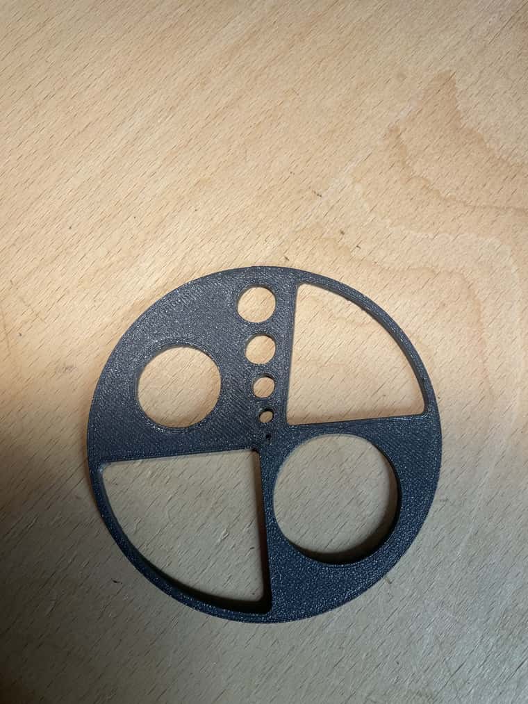
      IMG_3609-min.jpg
      IMG_3610-min.jpg

      Parts are sliced in SuperSlicer and orientation doesn't matter.
      Skew is already compensated and printed parts are all square.
      I checked belttension multiple times.

      There are only two things I am thinking of that could cause the problem but i am not sure about.
      Maybe something with jerk and acceleration values ? But while printing everything looks fine and smooth.
      The other thing is, that i am running the x-axis on an external StepperOnline DM542T stepper driver.
      link text
      I already switched the axis to an onboard Duet Wifi driver with the same result.

      I am very lost and would be very happy if somebody could help me.

      ; General preferences
      G90                                                ; send absolute coordinates...
      M83                                                ; ...but relative extruder moves
      M550 P"Machine m"                                  ; set printer name
      M669 K0                                            ; select Cartesian mode
      
      ; Network
      M552 S1                                            ; enable network
      M586 P0 S1                                         ; enable HTTP
      M586 P1 S0                                         ; disable FTP
      M586 P2 S0                                         ; disable Telnet
      
      ; Drives
      M569 P0 S0											; physical drive 0 goes forwards
      M569 P1 S0                                         ; physical drive 1 goes forwards
      M569 P2 S1                                         ; physical drive 2 goes forwards
      M569 P3 S1                                         ; physical drive 3 goes backwards
      M569 P4 S0 D2                                         ; physical drive 4 goes forwards
      M569 P5 S0 R1 T2.5:2.5:5:0							   ; drive 5 goes forwards
      M569 P6 S0 R1 T2.5:2.5:5:0							   ; drive 6 goes forwards
      M569 P7 S0 R1 T2.5:2.5:5:0							   ; drive 7 goes forwards
      M569 P8 S0 R1 T5:5:10:0                               ; physical drive 8 goes backwards	aa:bb:cc a=Step pulse width/ b=
      
      
      M584 X8 Y1:2 Z5:6:7 U0 E3:4                           ; set drive mapping
      M350 U16 Y16:16 Z16:16:16 E16:16 I1                ; configure microstepping with interpolation
      M92 X40.00 U80.00 Y53.33 Z640.00 E396.00:396.00                  ; set steps per mm (E old 390)
      M566 X400.00 U400.00 Y400.00 Z300.00 E3000.00                ; set maximum instantaneous speed changes (mm/min) 900
      M203 X20000.00 U20000.00 Y20000.00 Z2100.00 E3600.00            ; set maximum speeds (mm/min)
      M201 X2000.00 U2000.00 Y2000.00 Z400.00 E4000.00                ; set accelerations (mm/s^2) 4000
      M204 P4000 T5000				    					   ; Set print and travel accelrations [mm/s^2]
      M906 U1000 Y1800:1800 E1000:1000 I30                     	   ; set motor currents (mA) and motor idle factor in per cent
      ;M671 X390:-10:-10 Y200:5:390 S100 F1					; Leadscrew at rear front, back middle and rear front
      M671 X390:-10:-10 Y200:5:390					; Leadscrew at rear front, back middle and rear front
      M84 S30  
       
      
      ; Axis Limits
      M208 X-47 U25.5 Y-36 Z0 S1                                   ; set axis minima
      M208 X360 U436.7 Y417 Z300 S0                             ; set axis maxima
      M564 H0												; Allow axis movement before homing
      
      ; Endstops
      M574 X1 S1 P"e1stop"                                    ; set active high endstops for X-axis
      M574 U2 S1 P"xstop"										; set active high endstops for U-axis
      M574 Y1 S1 P"ystop+e0stop"								; set active high endstops for Y-axis; 2 enstops used
      ;M574 Y1 S1 P"e0stop"
      M574 Z2 S2                                        		; set endstops controlled by probe
      
      ; Z-Probe
      ;M558 C"!zprobe.mod" P5 R0.4 H1.5 F800:600 T12000 A2 I1 S0.1                     ; set Z probe type to effector and the dive height + speeds
      M558 C"!zprobe.mod" P5 R0.4 H4 F800:600 T12000 A2 I1 S0.1                     ; set Z probe type to effector and the dive height + speeds
      G31 X-0.5 Y-26.352 Z1.45 S20 H0                                ; set Z probe trigger value, offset and trigger height 1.58
      ;M557 X15:400 Y0:370 S40                           ; define mesh grid
      M557 X5:350 Y0:400 P7:7                           ; define mesh grid
      
      ; Heaters
      
      ; Bed
      M140 H0
      M308 S0 P"bedtemp" Y"thermistor" A"Bed Temperature" T100000 B3950 C7.06e-8 R4700
      M950 H0 C"bedheat" T0                                  ; create bed heater output on bedheat and map it to sensor 0
      M143 H0 S120                                           ; set temperature limit for heater 0 to 120C
      M307 H0 B1 S1
      
      
      ;Extruder E0 Hotend (E3D Hemera)
      M308 S1 P"e0temp" Y"thermistor" A"Extruder 1 temp." T100000 B4725 C7.06e-8 R4700
      M950 H1 C"e0heat" T1                                   ; create nozzle heater output on e0heat and map it to sensor 1
      M143 H1 S285                                           ; set temperature limit for heater 1 to 285C
      M307 H1 B0 A346.2 C189.8 D4.3 S1.0 		       ; Set heating process parameters, Heater1 (H1),Gain (A), time constant (C), Dead time (D), Max PWM 100% (S1.0)
      M302 P1											; Allow cold extrusion
      M572 D0 S0.025									; Preassure Advance
      
      ;Extruder E1 Hotend (E3D Hemera)
      M308 S2 P"e1temp" Y"thermistor" A"Extruder 2 temp." T100000 B4725 C7.06e-8 R4700
      M950 H2 C"e1heat" T2                                   ; create nozzle heater output on e0heat and map it to sensor 2
      M143 H2 S285                                           ; set temperature limit for heater 2 to 285C
      M307 H2 B0 A346.2 C189.8 D4.3 S1.0 		       ; Set heating process parameters, Heater2 (H2),Gain (A), time constant (C), Dead time (D), Max PWM 100% (S1.0)
      M302 P1											; Allow cold extrusion
      M572 D0 S0.03									; Preassure Advance
      
      
      ; Fans
      M950 F0 C"fan0"
      M950 F1 C"fan1"
      M106 P0 S0 H-1                             ; set fan 0 value, PWM signal inversion and frequency. Thermostatic control is turned off
      M106 P1 S0 H-1                             ; set fan 1 value, PWM signal inversion and frequency. Thermostatic control is turned on
      
      ; Tools
      M563 P0 S"ExtruderE0" D0 H1 F0 X0                                   ; define tool 0
      G10 P0 X0 Y0 Z0                                    ; set tool 0 axis offsets
      G10 P0 R0 S0                                       ; set initial tool 0 active and standby temperatures to 0C
      
      
      M563 P1 S"ExtruderE1" D1 H2 F1 X3                                  ; define tool 1
      G10 P1 U0.5 Y14.8 Z0                                    ; set tool 1 axis offsets
      G10 P1 R0 S0                                       ; set initial tool 1 active and standby temperatures to 0C
      
      T0
      
      ; Accelerometer
      M955 P0 I54 C"spi.cs4+spi.cs3" 						; Accelerometer Configuration
      M593 P"mzv" F36									;Input shaping at 33Hz; Damping: 0
      
      ; Custom settings are not defined
      M305 P2 S"Heizbett oben" T100000 B3950 C7.06e-8 R4700
      
      ; Miscellaneous
      M556 S100 X-1.058									Skew factor
      M501                                               ; load saved parameters from non-volatile memory
      M911 S10 R11 P"M913 X0 Y0 G91 M83 G1 Z3 E-5 F1000" ; set voltage thresholds and actions to run on power loss
      
      posted in Tuning and tweaking
      Manuel207undefined
      Manuel207