thanks for the reply.
what you you mean by:
@dc42 said in problem mesh bed. Delta printer:
most likely the tilt of your effector is varying with position
I got the printer mostly square and plum.
thanks in advance!
thanks for the reply.
what you you mean by:
@dc42 said in problem mesh bed. Delta printer:
most likely the tilt of your effector is varying with position
I got the printer mostly square and plum.
thanks in advance!
Hey,
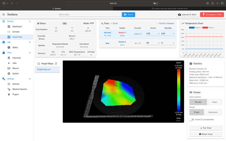
I got a really big delta printer with a Duet 6HC board, only thing I can't get working is the mesh bed level(See picture)
the probing works and also te hight map looks fine (I think).
can someone take a look at the files/pictures and help.
Thanks in advance!!!!
config file:
; Configuration file for Duet 3 MB 6HC (firmware version 3.3)
; executed by the firmware on start-up
;
; generated by RepRapFirmware Configuration Tool v3.4.1 on Sun May 05 2024 12:41:38 GMT+0200 (Central European Summer Time)

; General preferences
G90                                              ; send absolute coordinates...
M83                                              ; ...but relative extruder moves
M550 P"Svetlana"                                 ; set printer name
M665 R500 L1060 B483 H1468     ;B483                  ; Set delta radius, diagonal rod length, printable radius and homed height
M666 X0 Y0 Z0                                    ; put your endstop adjustments here, or let auto calibration find them

; Wait a moment for the CAN expansion boards to start
G4 S2

; Network
M552 P0.0.0.0 S1                                 ; enable network and acquire dynamic address via DHCP
M586 P0 S1                                       ; enable HTTP
M586 P1 S0                                       ; disable FTP
M586 P2 S0                                       ; disable Telnet

; Drives
M569 P0.0 S0                                     ; physical drive 0.0 goes backwards
M569 P0.1 S0                                     ; physical drive 0.1 goes backwards
M569 P0.2 S0                                     ; physical drive 0.2 goes backwards
M569 P20.0 S0                                     ; physical drive 0.3 goes forwards
M584 X0.0 Y0.1 Z0.2 E20.0                         ; set drive mapping
M350 X16 Y16 Z16 E16 I1                          ; configure microstepping with interpolation
M92 X80.00 Y80.00 Z80.00 E409.00                  ; set steps per mm
M566 X1200.00 Y1200.00 Z1200.00 E1200.00         ; set maximum instantaneous speed changes (mm/min)
M203 X18000.00 Y18000.00 Z18000.00 E1200.00      ; set maximum speeds (mm/min)
M201 X1000.00 Y1000.00 Z1000.00 E1000.00         ; set accelerations (mm/s^2)
M906 X2000 Y2000 Z2000 E800 I30                  ; set motor currents (mA) and motor idle factor in per cent
M84 S30                                          ; Set idle timeout

; Axis Limits
;M208 Z1500 S1                                    ; set minimum Z

; Endstops
M574 X2 S1 P"io0.in"                             ; configure switch-type (e.g. microswitch) endstop for high end on X via pin io0.in
M574 Y2 S1 P"io1.in"                             ; configure switch-type (e.g. microswitch) endstop for high end on Y via pin io1.in
M574 Z2 S1 P"io2.in"                             ; configure switch-type (e.g. microswitch) endstop for high end on Z via pin io2.in

; Z-Probe
M950 S0 C"20.io0.out"                           ; create servo pin 0 for BLTouch
M558 P9 C"20.io0.in" H10 F1000 T6000              ; set Z probe type to bltouch and the dive height + speeds
G31 P500 X36 Y24 Z4.1                             ; set Z probe trigger value, offset and trigger height
M557 R483 S200                                   ; define mesh grid

; Heaters
M308 S0 P"temp0" Y"thermistor" T100000 B4138     ; configure sensor 0 as thermistor on pin temp0
M950 H0 C"out0" T0                               ; create bed heater output on out0 and map it to sensor 0
M307 H0 R0.199 K0.344:0.000 D6.06 E1.35 S1.00 B0                                 ; enable bang-bang mode for the bed heater and set PWM limit
M140 H0                                          ; map heated bed to heater 0
M143 H0 S60                                     ; set temperature limit for heater 0 to 120C
M308 S1 P"20.temp0" Y"thermistor" T100000 B4138 ; configure sensor 1 as thermistor on pin 121.temp0
M950 H1 C"20.out0" T1                           ; create nozzle heater output on 121.out0 and map it to sensor 1
M307 H1 R1.528 K0.177:0.000 D9.18 E1.35 S1.00 B0 V23.9                                 ; disable bang-bang mode for heater  and set PWM limit
M143 H1 S300                                     ; set temperature limit for heater 1 to 300C


;RUNOUT SENSOR
M591 D0 P2 C"20.io1.in" S1                ;RUNOUT SENSOR


; Fans
M950 F0 C"20.out2" Q500                         ; create fan 0 on pin 121.out2 and set its frequency
M106 P0 S0 H1 T45                                ; set fan 0 value. Thermostatic control is turned on
M950 F1 C"20.out1" Q500                         ; create fan 1 on pin 121.out1 and set its frequency
M106 P1 S1 H-1                                   ; set fan 1 value. Thermostatic control is turned off

; Tools
M563 P0 S"hot end" D0 H1 F0                      ; define tool 0
G10 P0 X0 Y0 Z0                                  ; set tool 0 axis offsets
G10 P0 R0 S0                                     ; set initial tool 0 active and standby temperatures to 0C

; Custom settings are not defined
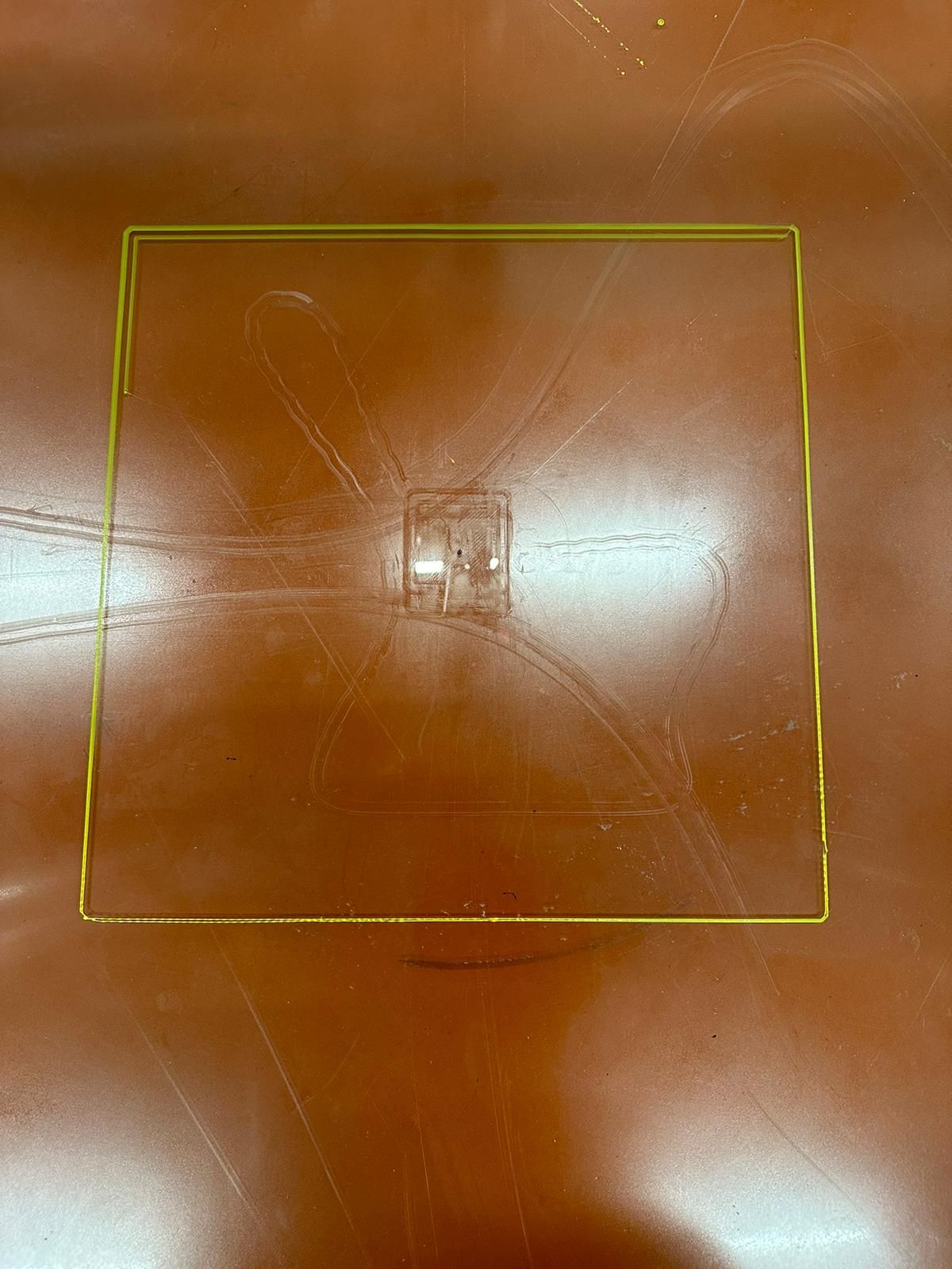
this is a picture of the first layer:
when I start the machine ill do a home all and then this macro to set the delta calibration and the mesh bed leveling:
G28	;homedelta
G0 X0 Y0 Z40 f10000
M557 X-380:380 Y-380:380 S200
M557 R400 S100
G30 ;set 0
G32	;delta cal
G29	;heighthmap
G0 X0 Y0 Z40 f10000
this is a example code from the picture (Just the setup part)
; G-Code generated by Simplify3D(R) Version 5.1.2
; Jun 11, 2024 at 10:22:32 PM
; Settings Summary
;   processName,Process 1
;   autoConfigureMaterial,PLA
;   autoConfigureQuality,Medium
;   targetModels,xyzCalibration_cube(2)(2)
;   profileName,Svetlana
;   profileVersion,2024-06-11 19:34:08
;   app,S3D-Software 5.1.2
;   technology,fff
;   baseProfile,
;   extruder,Extruder 1
;   toolheadNumber,0
;   nozzleDiameter,0.80000
;   extrusionMultiplier,1.00000
;   extrusionWidthMode,automatic
;   extrusionWidth,0.40000
;   useRetraction,1
;   retractDistance,1.00000
;   extraRestartDistance,0.00000
;   retractVerticalLift,0.00000
;   retractSpeed,1800.00000
;   useCoasting,0
;   coastingDistance,0.20000
;   useWiping,0
;   wipingDistance,5.00000
;   speedMaxFlowRate,900.00000
;   toolheadOffsetX,0.00000
;   toolheadOffsetY,0.00000
;   filamentDiameter,1.75000
;   filamentPricePerKilogram,25.00000
;   filamentDensity,1.25000
;   primaryExtruder,Extruder 1
;   layerHeight,0.20000
;   topSolidLayers,3
;   bottomSolidLayers,3
;   outlinePerimeters,2
;   useVaseMode,0
;   useAdaptiveLayerHeights,0
;   minAdaptiveLayerHeight,0.10000
;   maxAdaptiveLayerHeight,0.30000
;   adaptiveSmoothingLevel,5
;   horizontalOuterCompensation,0.00000
;   horizontalInnerCompensation,0.00000
;   firstLayerUnits,percentage
;   firstLayerHeightPercentage,100
;   firstLayerWidthPercentage,100
;   firstLayerSpeedPercentage,50
;   firstLayerHeightAbsolute,0.30000
;   firstLayerWidthAbsolute,0.40000
;   firstLayerSpeedAbsolute,900.00000
;   startPointStrategy,closest
;   alignStartPointsX,0.00000
;   alignStartPointsY,0.00000
;   restrictStartPoints,1
;   perimeterPrintingOrder,inside_out
;   islandPrintingOrder,closest
;   printInfillBeforePerimeters,0
;   useSkirt,1
;   skirtExtruder,Extruder 1
;   skirtLayers,1
;   skirtOffset,4.00000
;   skirtOutlines,2
;   useRaft,0
;   raftExtruder,Extruder 1
;   raftBaseLayers,2
;   raftTopLayers,3
;   raftOffset,3.00000
;   raftSeparationDistance,0.14000
;   raftSpeedUnits,percentage
;   raftSpeedPercentage,30
;   raftSpeedAbsolute,600.00000
;   usePrimePillar,0
;   primePillarExtruder,Extruder 1
;   primePillarWidth,12.00000
;   primePillarLocation,north_west
;   primePillarSpeedPercentage,100
;   primePillarInfillPercentage,100
;   autoStopPrimePillar,1
;   primePillarLayersAfterAutoStop,0
;   useOozeShield,0
;   oozeShieldExtruder,Extruder 1
;   oozeShieldOffset,2.00000
;   oozeShieldOutlines,1
;   oozeShieldSidewallShape,waterfall
;   oozeShieldSidewallAngle,30
;   oozeShieldSpeedPercentage,100
;   autoStopOozeShield,1
;   oozeShieldLayersAfterAutoStop,0
;   sparseInfillExtruder,Extruder 1
;   sparseInfillPattern,rectilinear
;   sparseInfillRotation,0
;   sparseInfillPercentage,20
;   sparseInfillExtrusionWidthPercentage,100
;   sparseInfillCombinedLayers,1
;   denseInfillLayers,0
;   denseInfillPercentage,50
;   infillOutlineOverlapPercentage,15
;   minInfillLength,5.00000
;   externalInfillPattern,rectilinear
;   externalInfillRotation,0
;   solidInfillThresholdArea,25.00000
;   solidInfillExtraExpansion,0.00000
;   useMonotonic,0
;   useDiaphragm,0
;   diaphragmSolidLayers,3
;   diaphragmSpacingLayers,20
;   topLayerExtraExpansion,1.00000
;   topLayerExtrusionModifier,100
;   overrideFanSpeedForTopLayer,0
;   topLayerFanSpeedPercentage,100
;   useIroning,0
;   ironingOutlineOffsetPercentage,50
;   ironingExtrusionWidthPercentage,25
;   ironingExtrusionModifier,15
;   ironingSpeedModifier,30
;   sparseSupportExtruder,Extruder 1
;   sparseSupportInfillPattern,aligned
;   sparseSupportInfillRotation,0
;   sparseSupportInfillPercentage,30
;   sparseSupportOutlines,0
;   sparseSupportCombinedLayers,1
;   upperDenseSupportLayers,0
;   lowerDenseSupportLayers,0
;   denseSupportExtruder,Extruder 1
;   denseSupportInfillPercentage,70
;   denseSupportExtraExpansion,0.00000
;   baseSupportLayers,0
;   supportInflationDistance,0.00000
;   supportHorizontalPartOffset,0.30000
;   supportUpperSeparationLayers,1
;   supportLowerSeparationLayers,1
;   temperatureController,Extruder 1
;   enableTemperatureController,1
;   temperatureNumber,0
;   temperatureType,extruder
;   stabilizeAtStartup,1
;   temperatureSetpoints,1|210
;   useIdleCooldown,0
;   cooldownTemperature,150
;   cooldownRequiredIdleTime,180
;   cooldownReheatTime,60
;   temperatureController,bed
;   enableTemperatureController,1
;   temperatureNumber,0
;   temperatureType,platform
;   stabilizeAtStartup,1
;   temperatureSetpoints,1|50
;   useIdleCooldown,0
;   cooldownTemperature,150
;   cooldownRequiredIdleTime,180
;   cooldownReheatTime,60
;   fan,Cooling Fan
;   fanNumber,0
;   fanType,extruder
;   blipFanToFullPower,0
;   fanSetpoints,1|0,2|100
;   increaseFanForQuickLayers,1
;   fanMaxQuickLayerTime,45.00000
;   fanMinQuickLayerTime,15.00000
;   maxQuickLayerFanSpeedPercentage,100
;   defaultPrintSpeed,1800.00000
;   outerPerimeterSpeedPercentage,60
;   innerPerimeterSpeedPercentage,80
;   topLayerSpeedPercentage,50
;   solidInfillSpeedPercentage,80
;   sparseSupportSpeedPercentage,80
;   denseSupportSpeedPercentage,70
;   travelSpeedXY,3600.00000
;   travelSpeedZ,2400.00000
;   reduceSpeedForQuickLayers,1
;   speedMaxQuickLayerTime,20.00000
;   minQuickLayerSpeedPercentage,30
;   reduceSpeedForShortPerimeters,1
;   speedMaxShortPerimeterLength,80.00000
;   minShortPerimeterSpeedPercentage,50
;   reduceSpeedForMaxFlowRate,0
;   accelXY,1000.00000
;   accelZ,150.00000
;   accelE,3000.00000
;   jerkXY,600.00000
;   jerkZ,24.00000
;   jerkE,300.00000
;   exportFileFormat,gcode
;   useStickyCommands,1
;   use5D,1
;   relativeExtrusionDistances,0
;   allowExtruderAxisZeroing,1
;   independentExtruderAxes,0
;   includeM10123,0
;   includeThumbnailImages,0
;   thumbnailImageEncoding,standard
;   thumbnailImageSizes,300|300
;   x3gMachineProfile,r2
;   overrideStepsPerMillimeter,0
;   stepsPerMillimeterX,88.57319
;   stepsPerMillimeterY,88.57319
;   stepsPerMillimeterZ,400.00000
;   stepsPerMillimeterA,96.27520
;   stepsPerMillimeterB,96.27520
;   xyzFileFormatVersion,1
;   makerBotMachineProfile,replicator_5
;   makerBotModelExtruder,mk13
;   makerBotSupportExtruder,mk14_s
;   makerBotModelMaterial,pla
;   makerBotSupportMaterial,pva
;   globalOffsetX,0.00000
;   globalOffsetY,0.00000
;   globalOffsetZ,0.00000
;   applyToolheadOffsets,0
;   buildVolumeShape,cylindrical
;   buildVolumeX,200.00000
;   buildVolumeY,200.00000
;   buildVolumeZ,1300.00000
;   buildVolumeDiameter,1000.00000
;   originOffsetX,500.00000
;   originOffsetY,500.00000
;   originOffsetZ,0.00000
;   homingDirectionX,center
;   homingDirectionY,center
;   homingDirectionZ,max
;   mirrorVisualX,0
;   mirrorVisualY,1
;   mirrorVisualZ,0
;   machineBackgroundModel,
;   startingScript,G0 x0 y0 Z40 F6000|G30|
;   preLayerChangeScript,
;   postLayerChangeScript,
;   preRetractionScript,
;   postRetractionScript,
;   preToolChangeScript,
;   postToolChangeScript,
;   processChangeScript,
;   endingScript,M104 S0 ; turn off extruder|M84 ; disable motors
;   postProcessingScript,
;   useBridging,1
;   bridgingThresholdArea,50.00000
;   bridgingInfillExtraExpansion,0.00000
;   bridgingExtrusionModifier,100
;   bridgingSpeedModifier,100
;   overrideFanSpeedForBridging,0
;   bridgingFanSpeedPercentage,100
;   useFixedBridgingAngle,0
;   fixedBridgingAngle,0
;   applyBridgingToPerimeters,0
;   bridgingPerimeterExtraOverlap,0.00000
;   minBridgingPerimeterLength,10.00000
;   useToolChangeRetraction,1
;   toolChangeRetractDistance,12.00000
;   toolChangeExtraRestartDistance,-0.50000
;   toolChangeRetractSpeed,600.00000
;   toolChangePrimeOnFirstUse,0
;   toolChangeRetractAtEnd,0
;   externalThinWallType,perimeters_only
;   internalThinWallType,gap_fill
;   thinWallAllowedOverlapPercentage,10
;   singleExtrusionMinLength,1.00000
;   singleExtrusionMinWidthPercentage,50
;   singleExtrusionMaxWidthPercentage,200
;   singleExtrusionEndpointExtensionDistance,0.20000
;   onlyRetractWhenCrossingOutlines,1
;   retractBetweenLayers,1
;   retractOnTopLayers,0
;   useRetractionMinTravel,0
;   retractionMinTravel,5.00000
;   useRetractionMinExtrusion,0
;   retractionMinExtrusion,3.00000
;   onlyVerticalLiftOnTopLayers,0
;   retractWhileWiping,0
;   wipingMode,outer_perimeter
;   avoidCrossingOutlines,0
;   maxMovementDetourFactor,3.00000
;   openLoopSlicingBehavior,heal
;   openLoopThickenWidth,0.50000
;   slicingRegionRepairMode,positive
G90
M82
M106 S0 P0
M140 S50
M190 S50
M104 S210 T0
M109 S210 T0
G0 x0 y0 Z40 F6000
G30
; process Process 1
; layer 1, Z = 0.2000
T0
G92 E0.00000
G1 E-1.00000 F1800
; feature skirt
; tool H0.2000 W0.960
G1 Z0.2000 F2400
G1 X201.778 Y200.186 F3600
G92 E0.00000
G1 E1.00000 F1800
G92 E0.00000
G1 X-202.729 Y200.186 E32.28947 F900
G1 X-205.915 Y196.999 E32.64921
G1 X-205.915 Y-207.507 E64.93868
G1 X-202.729 Y-210.694 E65.29842
thank you in advance!!
@droftarts said in problem mesh bed. Delta printer:
I notice you are using a BLTouch, but there's no X or Y offset in the G31 command. Is it permanently mounted next to the nozzle? If so, it should have an offset.
I see, changed the offset but kept the same problem.
new config file:
; Configuration file for Duet 3 MB 6HC (firmware version 3.3)
; executed by the firmware on start-up
;
; generated by RepRapFirmware Configuration Tool v3.4.1 on Sun May 05 2024 12:41:38 GMT+0200 (Central European Summer Time)

; General preferences
G90                                              ; send absolute coordinates...
M83                                              ; ...but relative extruder moves
M550 P"Svetlana"                                 ; set printer name
M665 R500 L1060 B483 H1468     ;B483                  ; Set delta radius, diagonal rod length, printable radius and homed height
M666 X0 Y0 Z0                                    ; put your endstop adjustments here, or let auto calibration find them

; Wait a moment for the CAN expansion boards to start
G4 S2

; Network
M552 P0.0.0.0 S1                                 ; enable network and acquire dynamic address via DHCP
M586 P0 S1                                       ; enable HTTP
M586 P1 S0                                       ; disable FTP
M586 P2 S0                                       ; disable Telnet

; Drives
M569 P0.0 S0                                     ; physical drive 0.0 goes backwards
M569 P0.1 S0                                     ; physical drive 0.1 goes backwards
M569 P0.2 S0                                     ; physical drive 0.2 goes backwards
M569 P20.0 S0                                     ; physical drive 0.3 goes forwards
M584 X0.0 Y0.1 Z0.2 E20.0                         ; set drive mapping
M350 X16 Y16 Z16 E16 I1                          ; configure microstepping with interpolation
M92 X80.00 Y80.00 Z80.00 E409.00                  ; set steps per mm
M566 X1200.00 Y1200.00 Z1200.00 E1200.00         ; set maximum instantaneous speed changes (mm/min)
M203 X18000.00 Y18000.00 Z18000.00 E1200.00      ; set maximum speeds (mm/min)
M201 X1000.00 Y1000.00 Z1000.00 E1000.00         ; set accelerations (mm/s^2)
M906 X2000 Y2000 Z2000 E800 I30                  ; set motor currents (mA) and motor idle factor in per cent
M84 S30                                          ; Set idle timeout

; Axis Limits
;M208 Z1500 S1                                    ; set minimum Z

; Endstops
M574 X2 S1 P"io0.in"                             ; configure switch-type (e.g. microswitch) endstop for high end on X via pin io0.in
M574 Y2 S1 P"io1.in"                             ; configure switch-type (e.g. microswitch) endstop for high end on Y via pin io1.in
M574 Z2 S1 P"io2.in"                             ; configure switch-type (e.g. microswitch) endstop for high end on Z via pin io2.in

; Z-Probe
M950 S0 C"20.io0.out"                           ; create servo pin 0 for BLTouch
M558 P9 C"20.io0.in" H10 F1000 T6000              ; set Z probe type to bltouch and the dive height + speeds
G31 P500 X36 Y24 Z4.1                             ; set Z probe trigger value, offset and trigger height
M557 R483 S200                                   ; define mesh grid

; Heaters
M308 S0 P"temp0" Y"thermistor" T100000 B4138     ; configure sensor 0 as thermistor on pin temp0
M950 H0 C"out0" T0                               ; create bed heater output on out0 and map it to sensor 0
M307 H0 R0.199 K0.344:0.000 D6.06 E1.35 S1.00 B0                                 ; enable bang-bang mode for the bed heater and set PWM limit
M140 H0                                          ; map heated bed to heater 0
M143 H0 S60                                     ; set temperature limit for heater 0 to 120C
M308 S1 P"20.temp0" Y"thermistor" T100000 B4138 ; configure sensor 1 as thermistor on pin 121.temp0
M950 H1 C"20.out0" T1                           ; create nozzle heater output on 121.out0 and map it to sensor 1
M307 H1 R1.528 K0.177:0.000 D9.18 E1.35 S1.00 B0 V23.9                                 ; disable bang-bang mode for heater  and set PWM limit
M143 H1 S300                                     ; set temperature limit for heater 1 to 300C


;RUNOUT SENSOR
M591 D0 P2 C"20.io1.in" S1                ;RUNOUT SENSOR


; Fans
M950 F0 C"20.out2" Q500                         ; create fan 0 on pin 121.out2 and set its frequency
M106 P0 S0 H1 T45                                ; set fan 0 value. Thermostatic control is turned on
M950 F1 C"20.out1" Q500                         ; create fan 1 on pin 121.out1 and set its frequency
M106 P1 S1 H-1                                   ; set fan 1 value. Thermostatic control is turned off

; Tools
M563 P0 S"hot end" D0 H1 F0                      ; define tool 0
G10 P0 X0 Y0 Z0                                  ; set tool 0 axis offsets
G10 P0 R0 S0                                     ; set initial tool 0 active and standby temperatures to 0C

; Custom settings are not defined
@droftarts said in problem mesh bed. Delta printer:
Can you post an image of the bed mesh that is produced?
there you go
this is a picture of the first layer:
when I start the machine ill do a home all and then this macro to set the delta calibration and the mesh bed leveling:
G28	;homedelta
G0 X0 Y0 Z40 f10000
M557 X-380:380 Y-380:380 S200
M557 R400 S100
G30 ;set 0
G32	;delta cal
G29	;heighthmap
G0 X0 Y0 Z40 f10000
this is a example code from the picture (Just the setup part)
; G-Code generated by Simplify3D(R) Version 5.1.2
; Jun 11, 2024 at 10:22:32 PM
; Settings Summary
;   processName,Process 1
;   autoConfigureMaterial,PLA
;   autoConfigureQuality,Medium
;   targetModels,xyzCalibration_cube(2)(2)
;   profileName,Svetlana
;   profileVersion,2024-06-11 19:34:08
;   app,S3D-Software 5.1.2
;   technology,fff
;   baseProfile,
;   extruder,Extruder 1
;   toolheadNumber,0
;   nozzleDiameter,0.80000
;   extrusionMultiplier,1.00000
;   extrusionWidthMode,automatic
;   extrusionWidth,0.40000
;   useRetraction,1
;   retractDistance,1.00000
;   extraRestartDistance,0.00000
;   retractVerticalLift,0.00000
;   retractSpeed,1800.00000
;   useCoasting,0
;   coastingDistance,0.20000
;   useWiping,0
;   wipingDistance,5.00000
;   speedMaxFlowRate,900.00000
;   toolheadOffsetX,0.00000
;   toolheadOffsetY,0.00000
;   filamentDiameter,1.75000
;   filamentPricePerKilogram,25.00000
;   filamentDensity,1.25000
;   primaryExtruder,Extruder 1
;   layerHeight,0.20000
;   topSolidLayers,3
;   bottomSolidLayers,3
;   outlinePerimeters,2
;   useVaseMode,0
;   useAdaptiveLayerHeights,0
;   minAdaptiveLayerHeight,0.10000
;   maxAdaptiveLayerHeight,0.30000
;   adaptiveSmoothingLevel,5
;   horizontalOuterCompensation,0.00000
;   horizontalInnerCompensation,0.00000
;   firstLayerUnits,percentage
;   firstLayerHeightPercentage,100
;   firstLayerWidthPercentage,100
;   firstLayerSpeedPercentage,50
;   firstLayerHeightAbsolute,0.30000
;   firstLayerWidthAbsolute,0.40000
;   firstLayerSpeedAbsolute,900.00000
;   startPointStrategy,closest
;   alignStartPointsX,0.00000
;   alignStartPointsY,0.00000
;   restrictStartPoints,1
;   perimeterPrintingOrder,inside_out
;   islandPrintingOrder,closest
;   printInfillBeforePerimeters,0
;   useSkirt,1
;   skirtExtruder,Extruder 1
;   skirtLayers,1
;   skirtOffset,4.00000
;   skirtOutlines,2
;   useRaft,0
;   raftExtruder,Extruder 1
;   raftBaseLayers,2
;   raftTopLayers,3
;   raftOffset,3.00000
;   raftSeparationDistance,0.14000
;   raftSpeedUnits,percentage
;   raftSpeedPercentage,30
;   raftSpeedAbsolute,600.00000
;   usePrimePillar,0
;   primePillarExtruder,Extruder 1
;   primePillarWidth,12.00000
;   primePillarLocation,north_west
;   primePillarSpeedPercentage,100
;   primePillarInfillPercentage,100
;   autoStopPrimePillar,1
;   primePillarLayersAfterAutoStop,0
;   useOozeShield,0
;   oozeShieldExtruder,Extruder 1
;   oozeShieldOffset,2.00000
;   oozeShieldOutlines,1
;   oozeShieldSidewallShape,waterfall
;   oozeShieldSidewallAngle,30
;   oozeShieldSpeedPercentage,100
;   autoStopOozeShield,1
;   oozeShieldLayersAfterAutoStop,0
;   sparseInfillExtruder,Extruder 1
;   sparseInfillPattern,rectilinear
;   sparseInfillRotation,0
;   sparseInfillPercentage,20
;   sparseInfillExtrusionWidthPercentage,100
;   sparseInfillCombinedLayers,1
;   denseInfillLayers,0
;   denseInfillPercentage,50
;   infillOutlineOverlapPercentage,15
;   minInfillLength,5.00000
;   externalInfillPattern,rectilinear
;   externalInfillRotation,0
;   solidInfillThresholdArea,25.00000
;   solidInfillExtraExpansion,0.00000
;   useMonotonic,0
;   useDiaphragm,0
;   diaphragmSolidLayers,3
;   diaphragmSpacingLayers,20
;   topLayerExtraExpansion,1.00000
;   topLayerExtrusionModifier,100
;   overrideFanSpeedForTopLayer,0
;   topLayerFanSpeedPercentage,100
;   useIroning,0
;   ironingOutlineOffsetPercentage,50
;   ironingExtrusionWidthPercentage,25
;   ironingExtrusionModifier,15
;   ironingSpeedModifier,30
;   sparseSupportExtruder,Extruder 1
;   sparseSupportInfillPattern,aligned
;   sparseSupportInfillRotation,0
;   sparseSupportInfillPercentage,30
;   sparseSupportOutlines,0
;   sparseSupportCombinedLayers,1
;   upperDenseSupportLayers,0
;   lowerDenseSupportLayers,0
;   denseSupportExtruder,Extruder 1
;   denseSupportInfillPercentage,70
;   denseSupportExtraExpansion,0.00000
;   baseSupportLayers,0
;   supportInflationDistance,0.00000
;   supportHorizontalPartOffset,0.30000
;   supportUpperSeparationLayers,1
;   supportLowerSeparationLayers,1
;   temperatureController,Extruder 1
;   enableTemperatureController,1
;   temperatureNumber,0
;   temperatureType,extruder
;   stabilizeAtStartup,1
;   temperatureSetpoints,1|210
;   useIdleCooldown,0
;   cooldownTemperature,150
;   cooldownRequiredIdleTime,180
;   cooldownReheatTime,60
;   temperatureController,bed
;   enableTemperatureController,1
;   temperatureNumber,0
;   temperatureType,platform
;   stabilizeAtStartup,1
;   temperatureSetpoints,1|50
;   useIdleCooldown,0
;   cooldownTemperature,150
;   cooldownRequiredIdleTime,180
;   cooldownReheatTime,60
;   fan,Cooling Fan
;   fanNumber,0
;   fanType,extruder
;   blipFanToFullPower,0
;   fanSetpoints,1|0,2|100
;   increaseFanForQuickLayers,1
;   fanMaxQuickLayerTime,45.00000
;   fanMinQuickLayerTime,15.00000
;   maxQuickLayerFanSpeedPercentage,100
;   defaultPrintSpeed,1800.00000
;   outerPerimeterSpeedPercentage,60
;   innerPerimeterSpeedPercentage,80
;   topLayerSpeedPercentage,50
;   solidInfillSpeedPercentage,80
;   sparseSupportSpeedPercentage,80
;   denseSupportSpeedPercentage,70
;   travelSpeedXY,3600.00000
;   travelSpeedZ,2400.00000
;   reduceSpeedForQuickLayers,1
;   speedMaxQuickLayerTime,20.00000
;   minQuickLayerSpeedPercentage,30
;   reduceSpeedForShortPerimeters,1
;   speedMaxShortPerimeterLength,80.00000
;   minShortPerimeterSpeedPercentage,50
;   reduceSpeedForMaxFlowRate,0
;   accelXY,1000.00000
;   accelZ,150.00000
;   accelE,3000.00000
;   jerkXY,600.00000
;   jerkZ,24.00000
;   jerkE,300.00000
;   exportFileFormat,gcode
;   useStickyCommands,1
;   use5D,1
;   relativeExtrusionDistances,0
;   allowExtruderAxisZeroing,1
;   independentExtruderAxes,0
;   includeM10123,0
;   includeThumbnailImages,0
;   thumbnailImageEncoding,standard
;   thumbnailImageSizes,300|300
;   x3gMachineProfile,r2
;   overrideStepsPerMillimeter,0
;   stepsPerMillimeterX,88.57319
;   stepsPerMillimeterY,88.57319
;   stepsPerMillimeterZ,400.00000
;   stepsPerMillimeterA,96.27520
;   stepsPerMillimeterB,96.27520
;   xyzFileFormatVersion,1
;   makerBotMachineProfile,replicator_5
;   makerBotModelExtruder,mk13
;   makerBotSupportExtruder,mk14_s
;   makerBotModelMaterial,pla
;   makerBotSupportMaterial,pva
;   globalOffsetX,0.00000
;   globalOffsetY,0.00000
;   globalOffsetZ,0.00000
;   applyToolheadOffsets,0
;   buildVolumeShape,cylindrical
;   buildVolumeX,200.00000
;   buildVolumeY,200.00000
;   buildVolumeZ,1300.00000
;   buildVolumeDiameter,1000.00000
;   originOffsetX,500.00000
;   originOffsetY,500.00000
;   originOffsetZ,0.00000
;   homingDirectionX,center
;   homingDirectionY,center
;   homingDirectionZ,max
;   mirrorVisualX,0
;   mirrorVisualY,1
;   mirrorVisualZ,0
;   machineBackgroundModel,
;   startingScript,G0 x0 y0 Z40 F6000|G30|
;   preLayerChangeScript,
;   postLayerChangeScript,
;   preRetractionScript,
;   postRetractionScript,
;   preToolChangeScript,
;   postToolChangeScript,
;   processChangeScript,
;   endingScript,M104 S0 ; turn off extruder|M84 ; disable motors
;   postProcessingScript,
;   useBridging,1
;   bridgingThresholdArea,50.00000
;   bridgingInfillExtraExpansion,0.00000
;   bridgingExtrusionModifier,100
;   bridgingSpeedModifier,100
;   overrideFanSpeedForBridging,0
;   bridgingFanSpeedPercentage,100
;   useFixedBridgingAngle,0
;   fixedBridgingAngle,0
;   applyBridgingToPerimeters,0
;   bridgingPerimeterExtraOverlap,0.00000
;   minBridgingPerimeterLength,10.00000
;   useToolChangeRetraction,1
;   toolChangeRetractDistance,12.00000
;   toolChangeExtraRestartDistance,-0.50000
;   toolChangeRetractSpeed,600.00000
;   toolChangePrimeOnFirstUse,0
;   toolChangeRetractAtEnd,0
;   externalThinWallType,perimeters_only
;   internalThinWallType,gap_fill
;   thinWallAllowedOverlapPercentage,10
;   singleExtrusionMinLength,1.00000
;   singleExtrusionMinWidthPercentage,50
;   singleExtrusionMaxWidthPercentage,200
;   singleExtrusionEndpointExtensionDistance,0.20000
;   onlyRetractWhenCrossingOutlines,1
;   retractBetweenLayers,1
;   retractOnTopLayers,0
;   useRetractionMinTravel,0
;   retractionMinTravel,5.00000
;   useRetractionMinExtrusion,0
;   retractionMinExtrusion,3.00000
;   onlyVerticalLiftOnTopLayers,0
;   retractWhileWiping,0
;   wipingMode,outer_perimeter
;   avoidCrossingOutlines,0
;   maxMovementDetourFactor,3.00000
;   openLoopSlicingBehavior,heal
;   openLoopThickenWidth,0.50000
;   slicingRegionRepairMode,positive
G90
M82
M106 S0 P0
M140 S50
M190 S50
M104 S210 T0
M109 S210 T0
G0 x0 y0 Z40 F6000
G30
; process Process 1
; layer 1, Z = 0.2000
T0
G92 E0.00000
G1 E-1.00000 F1800
; feature skirt
; tool H0.2000 W0.960
G1 Z0.2000 F2400
G1 X201.778 Y200.186 F3600
G92 E0.00000
G1 E1.00000 F1800
G92 E0.00000
G1 X-202.729 Y200.186 E32.28947 F900
G1 X-205.915 Y196.999 E32.64921
G1 X-205.915 Y-207.507 E64.93868
G1 X-202.729 Y-210.694 E65.29842
thank you in advance!!
I got a really big delta printer up and running with a duet 6HC and toolbar 1LC.
everything works fine apart from the mesh bed.
can't get a solid first layer, the Y direction is most of the problem. (See attached pictures)
can someone help me?
I'll share the following;
-Config.G
-Bed.G
-Simplify start Gcode and End Gcode
Config.G
; Configuration file for Duet 3 MB 6HC (firmware version 3.3)
; executed by the firmware on start-up
;
; generated by RepRapFirmware Configuration Tool v3.4.1 on Sun May 05 2024 12:41:38 GMT+0200 (Central European Summer Time)

; General preferences
G90                                              ; send absolute coordinates...
M83                                              ; ...but relative extruder moves
M550 P"Svetlana"                                 ; set printer name
M665 R483 L1060 B483 H1468     ;B483                  ; Set delta radius, diagonal rod length, printable radius and homed height
M666 X0 Y0 Z0                                    ; put your endstop adjustments here, or let auto calibration find them

; Wait a moment for the CAN expansion boards to start
G4 S2

; Network
M552 P0.0.0.0 S1                                 ; enable network and acquire dynamic address via DHCP
M586 P0 S1                                       ; enable HTTP
M586 P1 S0                                       ; disable FTP
M586 P2 S0                                       ; disable Telnet

; Drives
M569 P0.0 S0                                     ; physical drive 0.0 goes backwards
M569 P0.1 S0                                     ; physical drive 0.1 goes backwards
M569 P0.2 S0                                     ; physical drive 0.2 goes backwards
M569 P20.0 S0                                     ; physical drive 0.3 goes forwards
M584 X0.0 Y0.1 Z0.2 E20.0                         ; set drive mapping
M350 X16 Y16 Z16 E16 I1                          ; configure microstepping with interpolation
M92 X80.00 Y80.00 Z80.00 E409.00                  ; set steps per mm
M566 X1200.00 Y1200.00 Z1200.00 E1200.00         ; set maximum instantaneous speed changes (mm/min)
M203 X18000.00 Y18000.00 Z18000.00 E1200.00      ; set maximum speeds (mm/min)
M201 X1000.00 Y1000.00 Z1000.00 E1000.00         ; set accelerations (mm/s^2)
M906 X2000 Y2000 Z2000 E800 I30                  ; set motor currents (mA) and motor idle factor in per cent
M84 S30                                          ; Set idle timeout

; Axis Limits
;M208 Z1500 S1                                    ; set minimum Z

; Endstops
M574 X2 S1 P"io0.in"                             ; configure switch-type (e.g. microswitch) endstop for high end on X via pin io0.in
M574 Y2 S1 P"io1.in"                             ; configure switch-type (e.g. microswitch) endstop for high end on Y via pin io1.in
M574 Z2 S1 P"io2.in"                             ; configure switch-type (e.g. microswitch) endstop for high end on Z via pin io2.in

; Z-Probe
M950 S0 C"20.io0.out"                           ; create servo pin 0 for BLTouch
M558 P9 C"20.io0.in" H10 F1000 T6000              ; set Z probe type to bltouch and the dive height + speeds
G31 P500 X0 Y0 Z3.5                             ; set Z probe trigger value, offset and trigger height
M557 R483 S200                                   ; define mesh grid

; Heaters
M308 S0 P"temp0" Y"thermistor" T100000 B4138     ; configure sensor 0 as thermistor on pin temp0
M950 H0 C"out0" T0                               ; create bed heater output on out0 and map it to sensor 0
M307 H0 R0.199 K0.344:0.000 D6.06 E1.35 S1.00 B0                                 ; enable bang-bang mode for the bed heater and set PWM limit
M140 H0                                          ; map heated bed to heater 0
M143 H0 S60                                     ; set temperature limit for heater 0 to 120C
M308 S1 P"20.temp0" Y"thermistor" T100000 B4138 ; configure sensor 1 as thermistor on pin 121.temp0
M950 H1 C"20.out0" T1                           ; create nozzle heater output on 121.out0 and map it to sensor 1
M307 H1 R1.528 K0.177:0.000 D9.18 E1.35 S1.00 B0 V23.9                                 ; disable bang-bang mode for heater  and set PWM limit
M143 H1 S300                                     ; set temperature limit for heater 1 to 300C


;RUNOUT SENSOR
M591 D0 P2 C"20.io1.in" S1                ;RUNOUT SENSOR


; Fans
M950 F0 C"20.out2" Q500                         ; create fan 0 on pin 121.out2 and set its frequency
M106 P0 S0 H1 T45                                ; set fan 0 value. Thermostatic control is turned on
M950 F1 C"20.out1" Q500                         ; create fan 1 on pin 121.out1 and set its frequency
M106 P1 S1 H-1                                   ; set fan 1 value. Thermostatic control is turned off

; Tools
M563 P0 S"hot end" D0 H1 F0                      ; define tool 0
G10 P0 X0 Y0 Z0                                  ; set tool 0 axis offsets
G10 P0 R0 S0                                     ; set initial tool 0 active and standby temperatures to 0C

; Custom settings are not defined
Bed.G
; bed.g
; called to perform automatic delta calibration via G32
;
; generated by RepRapFirmware Configuration Tool v3.4.1 on Thu May 16 2024 15:48:45 GMT+0200 (Central European Summer Time)
M561 ; clear any bed transform
; Probe the bed at 3 peripheral and 3 halfway points, and perform 6-factor auto compensation
; Before running this, you should have set up your Z-probe trigger height to suit your build, in the G31 command in config.g.
G30 P0 X0 Y439.9 H0 Z-99999
G30 P1 X380.96 Y-219.95 H0 Z-99999
G30 P2 X-380.96 Y-219.95 H0 Z-99999
G30 P3 X0 Y219.9 H0 Z-99999
G30 P4 X190.44 Y-109.95 H0 Z-99999
G30 P5 X-190.44 Y-109.95 H0 Z-99999
G30 P6 X0 Y0 H0 Z-99999 S6
; Use S-1 for measurements only, without calculations. Use S4 for endstop heights and Z-height only. Use S6 for full 6 factors
; If your Z probe has significantly different trigger heights depending on XY position, adjust the H parameters in the G30 commands accordingly. The value of each H parameter should be (trigger height at that XY position) - (trigger height at centre of bed)
Start Gcode
G28 ; home all axes
G0 Z30 f4000 ;move down to buildplate
G30 ;Set z0
G32 ; delta calibratie
G29 ;make map bed
G29 S1 ; load map
G1 X0 X0 Y0 Z10 ;go centre
End Gcode
M104 S0 ; turn off extruder
M84 ; disable motors
Thank You! I updated both the toolboard and the mainboard and all problems disappeared.
03/05/2024, 10:09:03 M122
=== Diagnostics ===
RepRapFirmware for Duet 3 MB6HC version 3.3 (2021-06-15 21:45:47) running on Duet 3 MB6HC v1.01 or later (standalone mode)
Board ID: 08DJM-9P63L-DJMSS-6J1FL-3S86L-18DM9
Used output buffers: 1 of 40 (12 max)
=== RTOS ===
Static ram: 150904
Dynamic ram: 89720 of which 572 recycled
Never used RAM 112996, free system stack 200 words
Tasks: NETWORK(ready,28.2%,230) ETHERNET(notifyWait,0.1%,117) HEAT(delaying,0.0%,405) Move(notifyWait,0.0%,352) CanReceiv(notifyWait,0.0%,799) CanSender(notifyWait,0.0%,374) CanClock(delaying,0.0%,339) TMC(notifyWait,7.5%,93) MAIN(running,59.5%,1114) IDLE(ready,4.7%,29), total 100.0%
Owned mutexes:
=== Platform ===
Last reset 00:01:02 ago, cause: software
Last software reset at 2024-05-03 10:07, reason: User, GCodes spinning, available RAM 112996, slot 0
Software reset code 0x0003 HFSR 0x00000000 CFSR 0x00000000 ICSR 0x0044a000 BFAR 0x00000000 SP 0x00000000 Task MAIN Freestk 0 n/a
Error status: 0x00
Step timer max interval 127
MCU temperature: min 30.5, current 32.2, max 32.3
Supply voltage: min 23.7, current 23.7, max 23.8, under voltage events: 0, over voltage events: 0, power good: yes
12V rail voltage: min 12.0, current 12.1, max 12.1, under voltage events: 0
Heap OK, handles allocated/used 0/0, heap memory allocated/used/recyclable 0/0/0, gc cycles 0
Driver 0: position 192685, standstill, reads 20881, writes 14 timeouts 0, SG min/max 0/0
Driver 1: position 192685, standstill, reads 20881, writes 14 timeouts 0, SG min/max 0/0
Driver 2: position 192685, standstill, reads 20881, writes 14 timeouts 0, SG min/max 0/0
Driver 3: position 0, standstill, reads 20884, writes 11 timeouts 0, SG min/max 0/0
Driver 4: position 0, standstill, reads 20884, writes 11 timeouts 0, SG min/max 0/0
Driver 5: position 0, standstill, reads 20885, writes 11 timeouts 0, SG min/max 0/0
Date/time: 2024-05-03 10:09:03
Slowest loop: 3.94ms; fastest: 0.05ms
=== Storage ===
Free file entries: 10
SD card 0 detected, interface speed: 25.0MBytes/sec
SD card longest read time 0.9ms, write time 0.0ms, max retries 0
=== Move ===
DMs created 125, maxWait 0ms, bed compensation in use: none, comp offset 0.000
=== MainDDARing ===
Scheduled moves 0, completed moves 0, hiccups 0, stepErrors 0, LaErrors 0, Underruns [0, 0, 0], CDDA state -1
=== AuxDDARing ===
Scheduled moves 0, completed moves 0, hiccups 0, stepErrors 0, LaErrors 0, Underruns [0, 0, 0], CDDA state -1
=== Heat ===
Bed heaters = -1 -1 -1 -1 -1 -1 -1 -1 -1 -1 -1 -1, chamberHeaters = -1 -1 -1 -1
=== GCodes ===
Segments left: 0
Movement lock held by null
HTTP is idle in state(s) 0
Telnet is idle in state(s) 0
File is idle in state(s) 0
USB is idle in state(s) 0
Aux is idle in state(s) 0
Trigger is idle in state(s) 0
Queue is idle in state(s) 0
LCD is idle in state(s) 0
SBC is idle in state(s) 0
Daemon is idle in state(s) 0
Aux2 is idle in state(s) 0
Autopause is idle in state(s) 0
Code queue is empty.
=== CAN ===
Messages queued 328, received 994, lost 0, longest wait 3ms for reply type 6013, peak Tx sync delay 6, free buffers 49 (min 48), ts 313/312/0
Tx timeouts 0,0,0,0,0,0
=== Network ===
Slowest loop: 7.02ms; fastest: 0.02ms
Responder states: HTTP(0) HTTP(0) HTTP(0) HTTP(0) HTTP(0) HTTP(0) FTP(0) Telnet(0), 0 sessions Telnet(0), 0 sessions
HTTP sessions: 1 of 8
; Configuration file for Duet 3 MB 6HC (firmware version 3)
; executed by the firmware on start-up
;
; generated by RepRapFirmware Configuration Tool v3.4.1 on Thu May 02 2024 17:50:51 GMT+0200 (Central European Summer Time)
; General preferences
G90 ; send absolute coordinates...
M83 ; ...but relative extruder moves
M550 P"Svetlana" ; set printer name
M665 R483 L1060 B483 H1465 ; Set delta radius, diagonal rod length, printable radius and homed height
M666 X0 Y0 Z0 ; put your endstop adjustments here, or let auto calibration find them
; Wait a moment for the CAN expansion boards to start
G4 S2
; Network
M552 P0.0.0.0 S1 ; enable network and acquire dynamic address via DHCP
M586 P0 S1 ; enable HTTP
M586 P1 S0 ; disable FTP
M586 P2 S0 ; disable Telnet
; Drives
M569 P0.0 S0 ; physical drive 0.0 goes backwards
M569 P0.1 S0 ; physical drive 0.1 goes backwards
M569 P0.2 S0 ; physical drive 0.2 goes backwards
M569 P20.0 S1 ; physical drive 121.0 goes forwards
M584 X0.0 Y0.1 Z0.2 E20.0 ; set drive mapping
M350 X16 Y16 Z16 E16 I1 ; configure microstepping with interpolation
M92 X80.00 Y80.00 Z80.00 E397.00 ; set steps per mm
M566 X1200.00 Y1200.00 Z1200.00 E1200.00 ; set maximum instantaneous speed changes (mm/min)
M203 X18000.00 Y18000.00 Z18000.00 E1200.00 ; set maximum speeds (mm/min)
M201 X1000.00 Y1000.00 Z1000.00 E1000.00 ; set accelerations (mm/s^2)
M906 X1000 Y1000 Z1000 E800 I30 ; set motor currents (mA) and motor idle factor in per cent
M84 S30 ; Set idle timeout
; Axis Limits
M208 Z1465 S1 ; set minimum Z
; Endstops
M574 X1 S1 P"io0.in" ; configure switch-type (e.g. microswitch) endstop for low end on X via pin io0.in
M574 Y1 S1 P"io1.in" ; configure switch-type (e.g. microswitch) endstop for low end on Y via pin io1.in
M574 Z1 S1 P"io2.in" ; configure switch-type (e.g. microswitch) endstop for low end on Z via pin io2.in
; Z-Probe
M950 S0 C"20.io0.out" ; create servo pin 0 for BLTouch
M558 P9 C"20.io0.in" H10 F2500 T6000 ; set Z probe type to bltouch and the dive height + speeds
G31 P500 X0 Y0 Z2.5 ; set Z probe trigger value, offset and trigger height
M143 H1 S250
M557 R483 S200 ; define mesh grid
; HotEnd Heaters and Thermistor HotEnd
M308 S1 P"20.temp0" Y"20.thermistor" T100000 ;B4138 ; Set thermistor + ADC parameters for heater 1 HotEnd
M950 H1 C"20.out0" T1 ; Create HotEnd Heater
M307 H1 B0 S1.00 ; disable bang-bang mode for heater and set PWM limit
M143 H1 S280 ; set temperature limit for heater 1 to 280C
; Fans
M950 F0 C"121.out1" Q500 ; create fan 0 on pin 121.out1 and set its frequency
M106 P0 C"Hot end fan" S0 H0 T45 ; set fan 0 name and value. Thermostatic control is turned on
M950 F1 C"out5" Q500 ; create fan 1 on pin out5 and set its frequency
M106 P1 S1 H-1
; Tools
M563 P0 D0 H1 F0 ; define tool 0
G10 P0 X0 Y0 Z0 ; set tool 0 axis offsets
G10 P0 R0 S0 ; set initial tool 0 active and standby temperatures to 0C
; Custom settings are not defined
Hey!
I’m building a delta printer with the Toolboard 1LC as hot end. The BL touch en thermostat work perfectly via the toolboard. Only issue I got is the heater. Got it defined in the config.g but it stays off when I click the heater it should turn on and start heating but I can’t get it to show active.
When I put the normal out0 from the duet 3 6H it wil work.
Has anyone an idea? Thanks in advance