Duet3D Logo Duet3D
    • Tags
    • Documentation
    • Order
    • Register
    • Login
    1. Home
    2. byazici
    • Profile
    • Following 0
    • Followers 0
    • Topics 2
    • Posts 8
    • Best 1
    • Controversial 0
    • Groups 0

    byazici

    @byazici

    5
    Reputation
    8
    Profile views
    8
    Posts
    0
    Followers
    0
    Following
    Joined Last Online

    byazici Unfollow Follow

    Best posts made by byazici

    • External driver extension board for Maestro for those interested

      Hello,

      I'm using external drivers with my Maestro and some of my drivers require 5V differential signals so, I made a board that acts as a daughter board and it does not block the PT100 add-on card, does not block the expansion connector (it actually carries it up), or any other terminal and gets is 5V from the board.

      I'm not an electrical engineer and don't have that much knowledge in the area and I don't know if it's totally correct but, hey, it works.

      I don't have intentions on making money from this, it will be open-source but, I currently have a few boards made, if anyone is interested I can sell them, as I won't be needing them.

      Here are some pictures:

      2_1556716614617_duet3d_maestro_external3.jpg 1_1556716614617_duet3d_maestro_external2.jpg 0_1556716614616_duet3d_maestro_external1.jpg

      If you don't use "Enable" on your motors, you only need a single 75ALS192, single cap and terminals and two RJ45 jacks (I like to use CAT5 cable between board and driver.

      The board uses the onboard 5V but, if you require cleaner power, there is a jumper and terminal for another 5V connection.

      Thanks.

      posted in Third-party add-ons
      byaziciundefined
      byazici

    Latest posts made by byazici

    • External driver extension board for Maestro for those interested

      Hello,

      I'm using external drivers with my Maestro and some of my drivers require 5V differential signals so, I made a board that acts as a daughter board and it does not block the PT100 add-on card, does not block the expansion connector (it actually carries it up), or any other terminal and gets is 5V from the board.

      I'm not an electrical engineer and don't have that much knowledge in the area and I don't know if it's totally correct but, hey, it works.

      I don't have intentions on making money from this, it will be open-source but, I currently have a few boards made, if anyone is interested I can sell them, as I won't be needing them.

      Here are some pictures:

      2_1556716614617_duet3d_maestro_external3.jpg 1_1556716614617_duet3d_maestro_external2.jpg 0_1556716614616_duet3d_maestro_external1.jpg

      If you don't use "Enable" on your motors, you only need a single 75ALS192, single cap and terminals and two RJ45 jacks (I like to use CAT5 cable between board and driver.

      The board uses the onboard 5V but, if you require cleaner power, there is a jumper and terminal for another 5V connection.

      Thanks.

      posted in Third-party add-ons
      byaziciundefined
      byazici
    • RE: External drives limited at 25Khz

      I guess thats because the reprap configurator has a problem, because I did select the correct board and the correct external motors 5-E2 and 6-E3 but, it still appoints P0 and P1 in the config file. I guess you might want to report that.

      posted in Duet Hardware and wiring
      byaziciundefined
      byazici
    • RE: External drives limited at 25Khz

      Think I found it, correct me if I am wrong:

      I changed M569 P0 to P5 and P1 to P6, this seems to have fixed the issue...will test

      posted in Duet Hardware and wiring
      byaziciundefined
      byazici
    • RE: External drives limited at 25Khz

      Here is the config file:

      ; Configuration file for Duet Maestro (firmware version 1.21)
      ; executed by the firmware on start-up
      ;
      ; generated by RepRapFirmware Configuration Tool v2 on Sat Apr 13 2019 13:22:32 GMT+0300 (GMT+03:00)

      ; General preferences
      G90 ; Send absolute coordinates...
      M83 ; ...but relative extruder moves

      M667 S1 ; Select CoreXY mode

      ; Network
      M550 P"My Printer" ; Set machine name
      M552 P0.0.0.0 S1 ; Enable network and acquire dynamic address via DHCP
      M586 P0 S1 ; Enable HTTP
      M586 P1 S0 ; Disable FTP
      M586 P2 S0 ; Disable Telnet

      ; Drives
      M569 P0 S1 T3.3:3.3:6:0 ; Drive 0 goes forwards
      M569 P1 S1 T3.3:3.3:6:0 ; Drive 1 goes forwards
      M569 P2 S1 ; Drive 2 goes forwards
      M569 P3 S1 ; Drive 3 goes forwards
      M584 X5 Y6 Z2 E3 ; Apply custom drive mapping
      M350 Z16 E16 I1 ; Configure microstepping with interpolation
      M92 X100.00 Y100.00 Z1280.00 E420.00 ; Set steps per mm
      M566 X900.00 Y900.00 Z900.00 E120.00 ; Set maximum instantaneous speed changes (mm/min)
      M203 X90000.00 Y90000.00 Z3000.00 E1200.00 ; Set maximum speeds (mm/min)
      M201 X1000.00 Y1000.00 Z20.00 E250.00 ; Set accelerations (mm/s^2)
      M906 X15.00 Y15.00 Z1500.00 E800.00 I30 ; Set motor currents (mA) and motor idle factor in per cent
      M84 S30 ; Set idle timeout

      ; Axis Limits
      M208 X0 Y0 Z0 S1 ; Set axis minima
      M208 X10000 Y10000 Z400 S0 ; Set axis maxima

      ; Endstops
      M574 X0 Y0 Z0 S0 ; Set active low and disabled endstops

      ; Z-Probe
      M558 P0 H0 F120 T18000 ; Disable Z probe but set dive height, probe speed and travel speed
      M557 X8:216 Y8:316 S20 ; Define mesh grid

      ; Heaters
      M140 H-1 ; Disable heated bed
      M305 P1 T100000 B4138 R2200 ; Set thermistor + ADC parameters for heater 1
      M143 H1 S280 ; Set temperature limit for heater 1 to 280C

      ; Fans
      M106 P0 S0 I0 F500 H T45 ; Set fan 0 value, PWM signal inversion and frequency. Thermostatic control is turned on
      M106 P1 S1 I0 F500 H T45 ; Set fan 1 value, PWM signal inversion and frequency. Thermostatic control is turned on

      ; Tools
      M563 P0 D0 H1 ; Define tool 0
      G10 P0 X0 Y0 Z0 ; Set tool 0 axis offsets
      G10 P0 R0 S0 ; Set initial tool 0 active and standby temperatures to 0C

      ; Automatic saving after power loss is not enabled

      ; Custom settings
      M918 P1 ;initialize display
      M564 H0

      posted in Duet Hardware and wiring
      byaziciundefined
      byazici
    • RE: External drives limited at 25Khz

      OK, so, I have upgraded to the latest 2.03beta3 (2019-03-25b6) firmware. The problem continues...

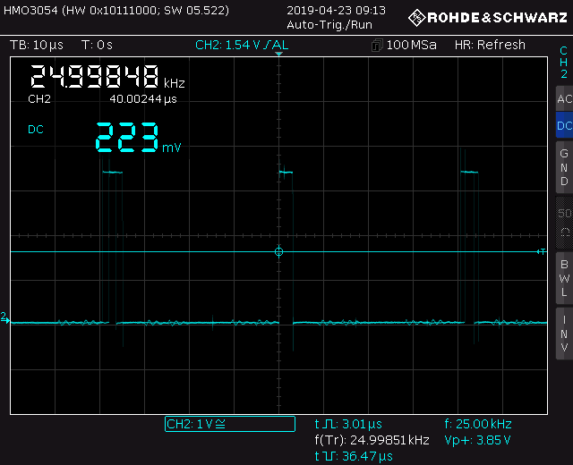
      Here, the signal is at 25kHz:

      0_1556008608949_SCR02.PNG

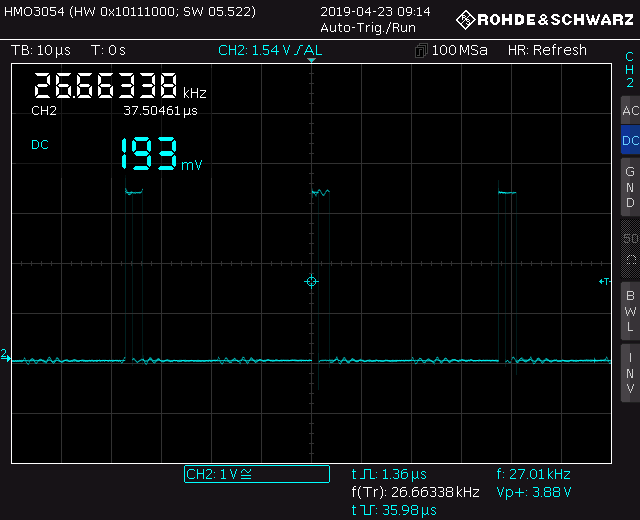
      Here the signal is at 27kHz, where you can see the 1.36us signal, which creates a problem:

      0_1556008646914_SCR03.PNG

      posted in Duet Hardware and wiring
      byaziciundefined
      byazici
    • RE: External drives limited at 25Khz

      Firmware is 2.02RC5(RTOS) (2018-11-28b1)

      posted in Duet Hardware and wiring
      byaziciundefined
      byazici
    • RE: External drives limited at 25Khz

      I have also uploaded a ss from Saleae Logic analyzer, you can see some of the pointers and the measurements that I took from the signal on the right side.
      0_1555951406244_logic.jpg

      posted in Duet Hardware and wiring
      byaziciundefined
      byazici
    • External drives limited at 25Khz

      Hello,

      First of all, let me define my setup:

      • Duet3D Maestro
      • 1x NEMA 23 Z motor
      • 2x External NEMA 23 motors (OMC stepper iss24 https://www.omc-stepperonline.com/download/ISS24.pdf)
      • Core XY setup

      The other items in my setup are irrelevant to my problem.

      I have the config file configured according to posts that I have read on the forum that have a similar setup to mine, which is T3.3:3.3:6:0, and it works up to a point and that point seems to be right around 25kHz for each motor. Any feed that I try to give above that results in lost steps.

      So, I hooked up the output from E3 port to an oscilloscope (Hameg HMO3004) to find out that when I cross the 25kHz boundary, the pulse lengths keep varying between 3.3us and 1.24us, which explains the lost steps as my drive does not accept anything lower than 2.5us but, what is interesting is the pulse-to-pulse time is calculated correct. So, when I increase the feed, lets say, to get a 33.3kHz motion, the pulse length and the gap in between the pulse is correctly set at 33.3kHz but, the pulse length is varrying between the set 3.3us to 1.24us, which baffles me.

      What could be causing this?

      Thank you.

      posted in Duet Hardware and wiring
      byaziciundefined
      byazici