Solved: How to use Leadshine Closed-Loop External Motor Drivers with Duet 2 Wifi and Breakout Expansion Board
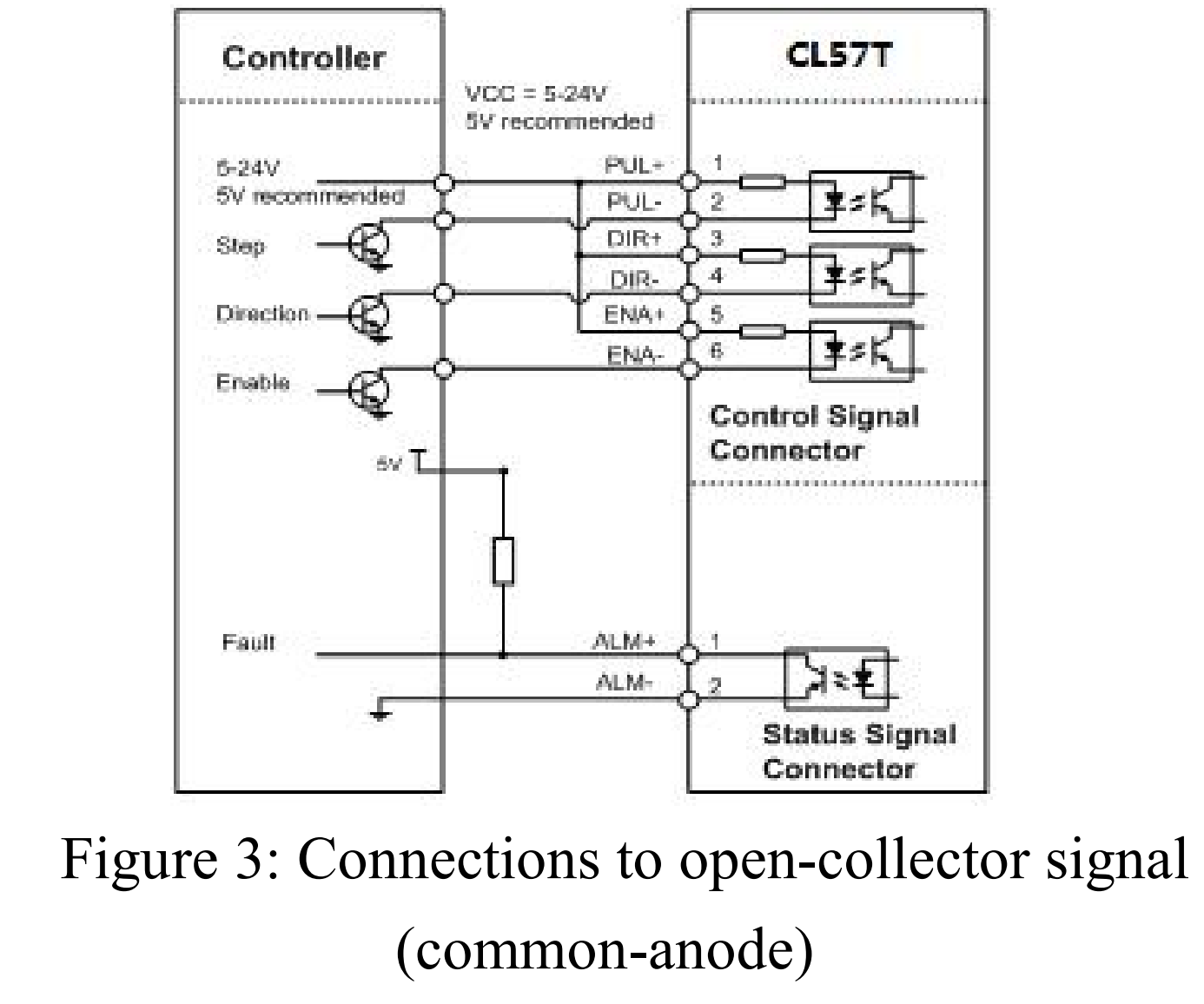
Note: I have wired the external drivers as "Common-Anode" and have supplied them with a +5v power supply. I have also set the DIP Switches to be 6400 Pulses/Revolution.
1- Start with a fresh config file and run through the basic setup as you would for any printer. I used the RRF Config Tool that can be found here: https://configtool.reprapfirmware.org/Start
2- Now go into the Config file and make the following adjustments. (do this before you try using the machine)
Set the M569 values for all of the External Motor Driver Axis
-
in the Config file place the M569 Parameters before all other drive settings. for me this was just after the network settings.
-
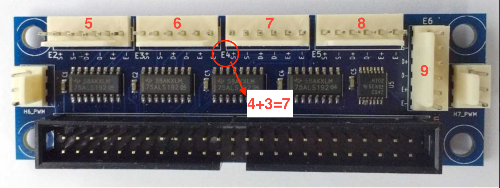
The "P" parameter is very straight forward. Just put the Pin Number from the Expansion Board for each axis. You can find this by looking for the Printed Labels next to each Header and add then add 3.
-
The "S" parameter will be determined by your machine layout. you can always come back and change this if an Axis is running in the wrong direction.
-
Set the "R" parameter to "R1" Active High
-
Use the "Taa:bb:cc:dd" parameter and set it to "T5:2.5:5:7.5" (5us minimum step pulse, 2.5us minimum step interval, 5us DIR setup time and 7.5 hold time. This is the setting I found that worked will all of the different Leadshine Closed-Loop External Motor Drivers I have. if these setting do not work for you begin increasing the minimum step pulse (aa) by intervals of 0.5 until it they work. You can also try reducing the minimum step pulse (aa) and the hold time (dd) by intervals of 0.5 to increase motor speed however these settings are probably plenty fast. Note: Make sure that you do not set the minimum step pulse (aa) below a value of 2.5
-
The finished M569 parameters should look like this: M569 P7 S0 R1 T5:2.5:5:7.5 Make sure to do this for all of the External Headers you are using.
3- Next add the Drive Mapping Parameter M584 to your Config File. Note: Make sure that this comes after the M569 parameters.
Simply match the Header Numbers to the Axis that you have wired them to.
mine ended up looking like this: M584 X7 Y6 Z5 E9
With these setting uploaded you should now be able to move each axis on the machine. once you have verified that all of the External Drivers are moving the stepper motors without an unexpected sounds or movements, you will need to go through the process of setting the M92 (steps per mm) parameter.
You Should now be ready to print! 
After much trial and error, here is what my Drive Settings in my Config File ended up looking like.
; Drive Settings
; Drives driver direction, enable polarity and step pulse timing
;------------------X MOTOR-------------------------------------------------------------
M569 P7 S0 R1 T5:2.5:5:7.5 ; driver 7 direction is backwards and requires an active high enable, 5us minimum step pulse, 2.5us minimum step interval, 5us DIR setup, and 7.5us hold time
;------------------Y MOTOR-------------------------------------------------------------
M569 P6 S0 R1 T5:2.5:5:7.5 ; driver 6 direction is backwards and requires an active high enable, 5us minimum step pulse, 2.5us minimum step interval, 5us DIR setup, and 7.5us hold time
;-----------------Z MOTOR--------------------------------------------------------------
M569 P5 S0 R1 T5:2.5:5:7.5 ; driver 5 direction is backwards and requires an active high enable, 5us minimum step pulse, 2.5us minimum step interval, 5us DIR setup, and 7.5us hold time
;-----------------EXTRUDER 0 MOTOR-----------------------------------------------------
M569 P9 S0 R1 T5:2.5:5:7.5 ; driver 9 direction is backwards and requires an active high enable, 5us minimum step pulse, 2.5us minimum step interval, 5us DIR setup, and 7.5us hold time
M584 X7 Y6 Z5 E9				   ; set drive mapping to external drivers
M92 X171.00 Y171.00 Z1290.00 E400.00               ; set steps per mm
M566 X100.00 Y100.00 Z60.00 E120.00                ; set maximum instantaneous speed changes (mm/min)
M203 X2000.00 Y2000.00 Z180.00 E1200.00            ; set maximum speeds (mm/min)
M201 X100.00 Y100.00 Z100.00 E1000.00              ; set accelerations (mm/s^2)
M906 X1000 Y1000 Z1000 E1000 I30                   ; set motor currents (mA) and motor idle factor in per cent
M84 S30                                            ; Set idle timeout
I found this information to be hard to find, but the community here helped me piece it together so I though it would be good to compile it all in one location. I hope that this will help you through your build!