@mrehorstdmd I am mostly using the Closed Loop system to detect/prevent collisions because of the high speeds that I am running the printer at and Id like the machine to not destroy itself. They are very good at maintaining position at high speeds and after pausing. I have noticed that they do not seem to perform well with coasting setting in prints. I am working on a new print cooling system and should be able to increase my speeds.
Posts made by Cameron
-
RE: Solved: Leadshine Closed-Loop External Motor Drivers with Duet2posted in General Discussion
-
RE: Solved: Leadshine Closed-Loop External Motor Drivers with Duet2posted in General Discussion
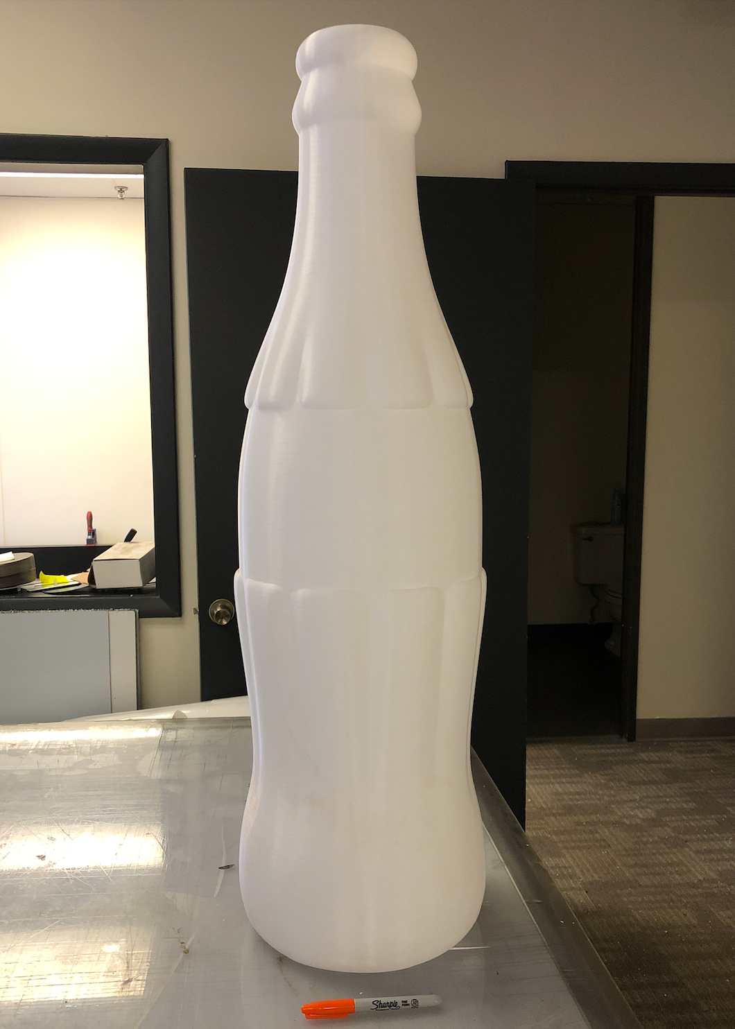
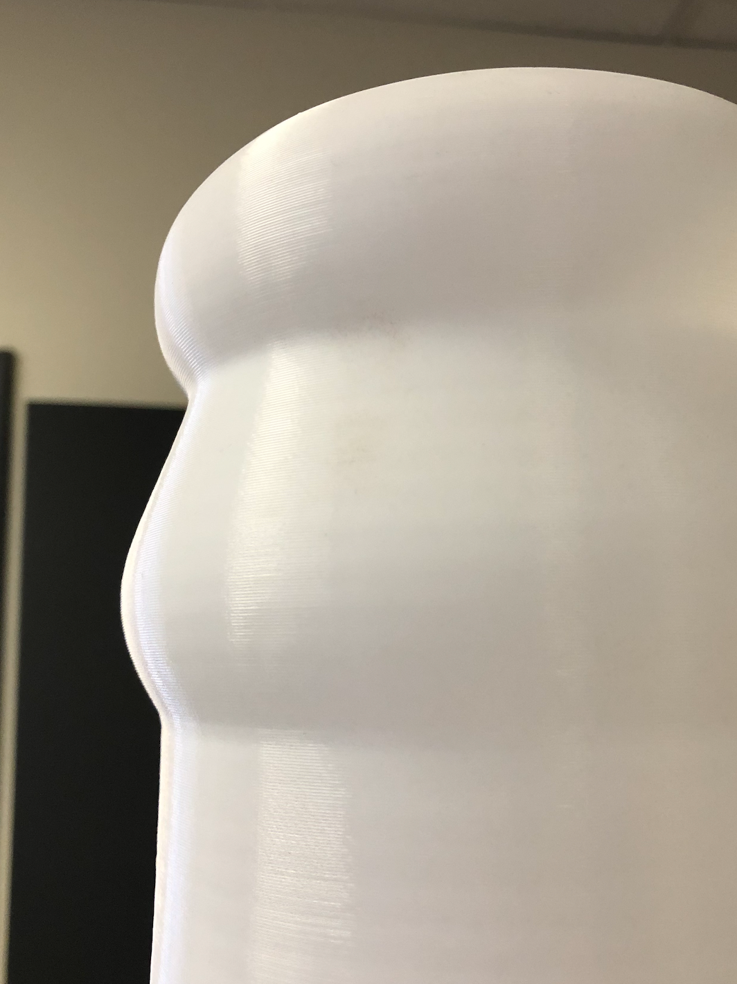
@OwenD Here are some initial results. I am still working on tuning the machine and am currently working on a new extruder/hotend design, but so far I am quite happy with the prints. This Bottle is almost 1 meter tall and used 1Kg of material. I printed it spiralized at .8mm layer height and it tool just over 3 hours. Once I have designed the new extruder assembly I will post an update. my goal is to get to 1kg of material in under an hour and maintain a decent print quality.
Orange Sharpie for Scale

-
Solved: Leadshine Closed-Loop External Motor Drivers with Duet2posted in General Discussion
Solved: How to use Leadshine Closed-Loop External Motor Drivers with Duet 2 Wifi and Breakout Expansion Board
Note: I have wired the external drivers as "Common-Anode" and have supplied them with a +5v power supply. I have also set the DIP Switches to be 6400 Pulses/Revolution.
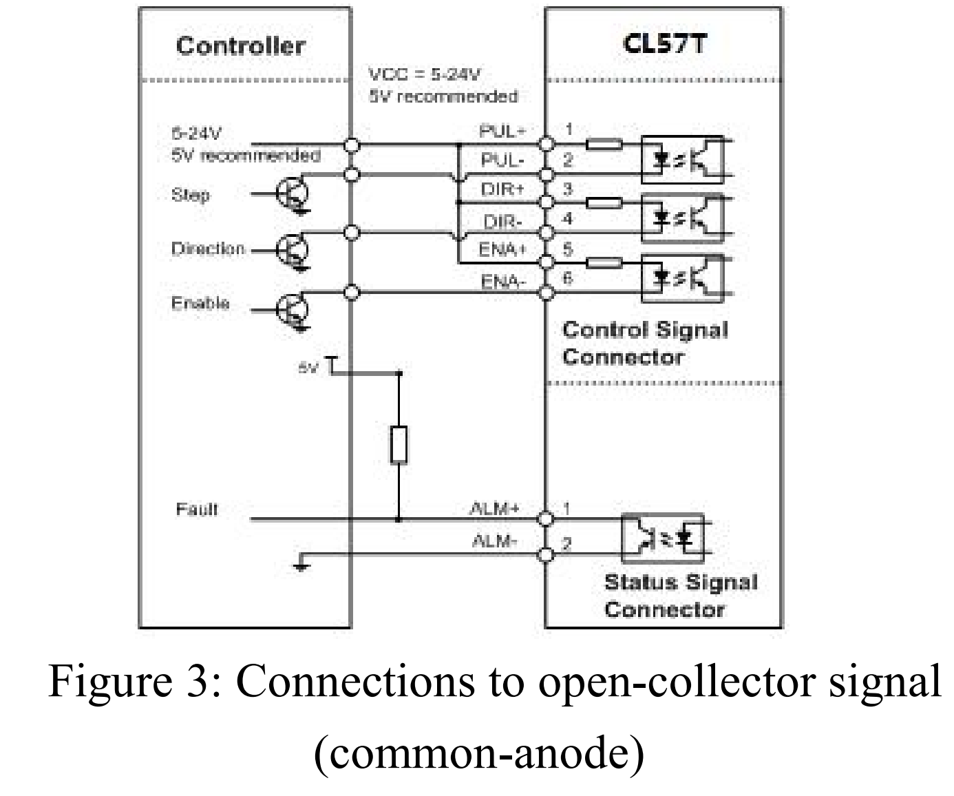
1- Start with a fresh config file and run through the basic setup as you would for any printer. I used the RRF Config Tool that can be found here: https://configtool.reprapfirmware.org/Start
2- Now go into the Config file and make the following adjustments. (do this before you try using the machine)
Set the M569 values for all of the External Motor Driver Axis
-
in the Config file place the M569 Parameters before all other drive settings. for me this was just after the network settings.
-
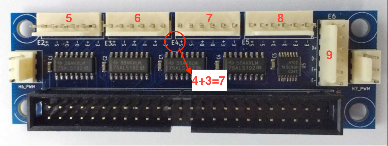
The "P" parameter is very straight forward. Just put the Pin Number from the Expansion Board for each axis. You can find this by looking for the Printed Labels next to each Header and add then add 3.
-
The "S" parameter will be determined by your machine layout. you can always come back and change this if an Axis is running in the wrong direction.
-
Set the "R" parameter to "R1" Active High
-
Use the "Taa:bb:cc:dd" parameter and set it to "T5:2.5:5:7.5" (5us minimum step pulse, 2.5us minimum step interval, 5us DIR setup time and 7.5 hold time. This is the setting I found that worked will all of the different Leadshine Closed-Loop External Motor Drivers I have. if these setting do not work for you begin increasing the minimum step pulse (aa) by intervals of 0.5 until it they work. You can also try reducing the minimum step pulse (aa) and the hold time (dd) by intervals of 0.5 to increase motor speed however these settings are probably plenty fast. Note: Make sure that you do not set the minimum step pulse (aa) below a value of 2.5
-
The finished M569 parameters should look like this: M569 P7 S0 R1 T5:2.5:5:7.5 Make sure to do this for all of the External Headers you are using.
3- Next add the Drive Mapping Parameter M584 to your Config File. Note: Make sure that this comes after the M569 parameters.
Simply match the Header Numbers to the Axis that you have wired them to.
mine ended up looking like this: M584 X7 Y6 Z5 E9With these setting uploaded you should now be able to move each axis on the machine. once you have verified that all of the External Drivers are moving the stepper motors without an unexpected sounds or movements, you will need to go through the process of setting the M92 (steps per mm) parameter.
You Should now be ready to print!

After much trial and error, here is what my Drive Settings in my Config File ended up looking like.
; Drive Settings
; Drives driver direction, enable polarity and step pulse timing
;------------------X MOTOR-------------------------------------------------------------
M569 P7 S0 R1 T5:2.5:5:7.5 ; driver 7 direction is backwards and requires an active high enable, 5us minimum step pulse, 2.5us minimum step interval, 5us DIR setup, and 7.5us hold time
;------------------Y MOTOR-------------------------------------------------------------
M569 P6 S0 R1 T5:2.5:5:7.5 ; driver 6 direction is backwards and requires an active high enable, 5us minimum step pulse, 2.5us minimum step interval, 5us DIR setup, and 7.5us hold time
;-----------------Z MOTOR--------------------------------------------------------------
M569 P5 S0 R1 T5:2.5:5:7.5 ; driver 5 direction is backwards and requires an active high enable, 5us minimum step pulse, 2.5us minimum step interval, 5us DIR setup, and 7.5us hold time
;-----------------EXTRUDER 0 MOTOR-----------------------------------------------------
M569 P9 S0 R1 T5:2.5:5:7.5 ; driver 9 direction is backwards and requires an active high enable, 5us minimum step pulse, 2.5us minimum step interval, 5us DIR setup, and 7.5us hold time
M584 X7 Y6 Z5 E9				   ; set drive mapping to external drivers
M92 X171.00 Y171.00 Z1290.00 E400.00               ; set steps per mm
M566 X100.00 Y100.00 Z60.00 E120.00                ; set maximum instantaneous speed changes (mm/min)
M203 X2000.00 Y2000.00 Z180.00 E1200.00            ; set maximum speeds (mm/min)
M201 X100.00 Y100.00 Z100.00 E1000.00              ; set accelerations (mm/s^2)
M906 X1000 Y1000 Z1000 E1000 I30                   ; set motor currents (mA) and motor idle factor in per cent
M84 S30                                            ; Set idle timeout
I found this information to be hard to find, but the community here helped me piece it together so I though it would be good to compile it all in one location. I hope that this will help you through your build!
-
-
RE: Y Axis loses steps on layer change. External Drivers.posted in Tuning and tweaking
the goal is to both get this printer to print properly, but also fast because of its large build volume I would rather have a fast print than an accurate print. if there are any settings that I should change that can help optimize for this please let me know.
-
RE: Y Axis loses steps on layer change. External Drivers.posted in Tuning and tweaking
I have tested with greater T values as-well as slower speed and acceleration. thee test resulted in significantly slower printing and the prints still have the shift in the Y axis each layer, although the distance of the shift was reduced. Here is the Diagnostic report:
M122
=== Diagnostics ===
RepRapFirmware for Duet 2 WiFi/Ethernet version 2.05.1 running on Duet WiFi 1.02 or later
Board ID: 08DGM-917DA-G4MS4-6J9DG-3SN6S-9SXR8
Used output buffers: 3 of 24 (9 max)
=== RTOS ===
Static ram: 25712
Dynamic ram: 93184 of which 0 recycled
Exception stack ram used: 432
Never used ram: 11744
Tasks: NETWORK(ready,628) HEAT(blocked,1232) MAIN(running,3824) IDLE(ready,160)
Owned mutexes:
=== Platform ===
Last reset 00:16:49 ago, cause: software
Last software reset time unknown, reason: User, spinning module GCodes, available RAM 11736 bytes (slot 0)
Software reset code 0x0003 HFSR 0x00000000 CFSR 0x00000000 ICSR 0x0441f000 BFAR 0xe000ed38 SP 0xffffffff Task 0x4e49414d
Error status: 0
Free file entries: 10
SD card 0 detected, interface speed: 20.0MBytes/sec
SD card longest block write time: 24.2ms, max retries 0
MCU temperature: min 29.9, current 31.5, max 31.9
Supply voltage: min 1.1, current 24.0, max 24.2, under voltage events: 0, over voltage events: 0, power good: yes
Driver 0: standstill, SG min/max not available
Driver 1: standstill, SG min/max not available
Driver 2: standstill, SG min/max not available
Driver 3: standstill, SG min/max not available
Driver 4: standstill, SG min/max not available
Date/time: 2020-06-14 12:05:02
Cache data hit count 3022018625
Slowest loop: 20.31ms; fastest: 0.05ms
I2C nak errors 0, send timeouts 0, receive timeouts 0, finishTimeouts 0, resets 0
=== Move ===
Hiccups: 0, FreeDm: 160, MinFreeDm: 154, MaxWait: 132470ms
Bed compensation in use: none, comp offset 0.000
=== DDARing ===
Scheduled moves: 0, completed moves: 0, StepErrors: 0, LaErrors: 0, Underruns: 0, 0
=== Heat ===
Bed heaters = 0 -1 -1 -1, chamberHeaters = -1 -1
Heater 1 is on, I-accum = 0.2
=== GCodes ===
Segments left: 0
Stack records: 1 allocated, 0 in use
Movement lock held by null
http is idle in state(s) 0
telnet is idle in state(s) 0
file is idle in state(s) 0
serial is idle in state(s) 0
aux is idle in state(s) 0
daemon is idle in state(s) 0
queue is idle in state(s) 0
autopause is idle in state(s) 0
Code queue is empty.
=== Network ===
Slowest loop: 35.84ms; fastest: 0.00ms
Responder states: HTTP(0) HTTP(0) HTTP(0) HTTP(0) FTP(0) Telnet(0) Telnet(0)
HTTP sessions: 1 of 8- WiFi -
Network state is running
WiFi module is connected to access point
Failed messages: pending 0, notready 0, noresp 0
WiFi firmware version 1.23
WiFi MAC address 60:01:94:2e:cd:49
WiFi Vcc 3.40, reset reason Turned on by main processor
WiFi flash size 4194304, free heap 23880
WiFi IP address 192.168.1.112
WiFi signal strength -64dBm, reconnections 0, sleep mode modem
Socket states: 0 0 0 0 0 0 0 0
- WiFi -
-
RE: Y Axis loses steps on layer change. External Drivers.posted in Tuning and tweaking
I cant figure out why the Y axis is shifting over on each layer. I have tries to change the M569 Settings and have only made things worse... any ideas on how I can narrow down this problem would be great!
-
RE: Y Axis loses steps on layer change. External Drivers.posted in Tuning and tweaking
@JoergS5 The Printer is a Large 1000x1000x1000 Chinese Printer That I Gutted and replaced all of the electrical components except for the motors and drivers. Here are a few Pictures of that:
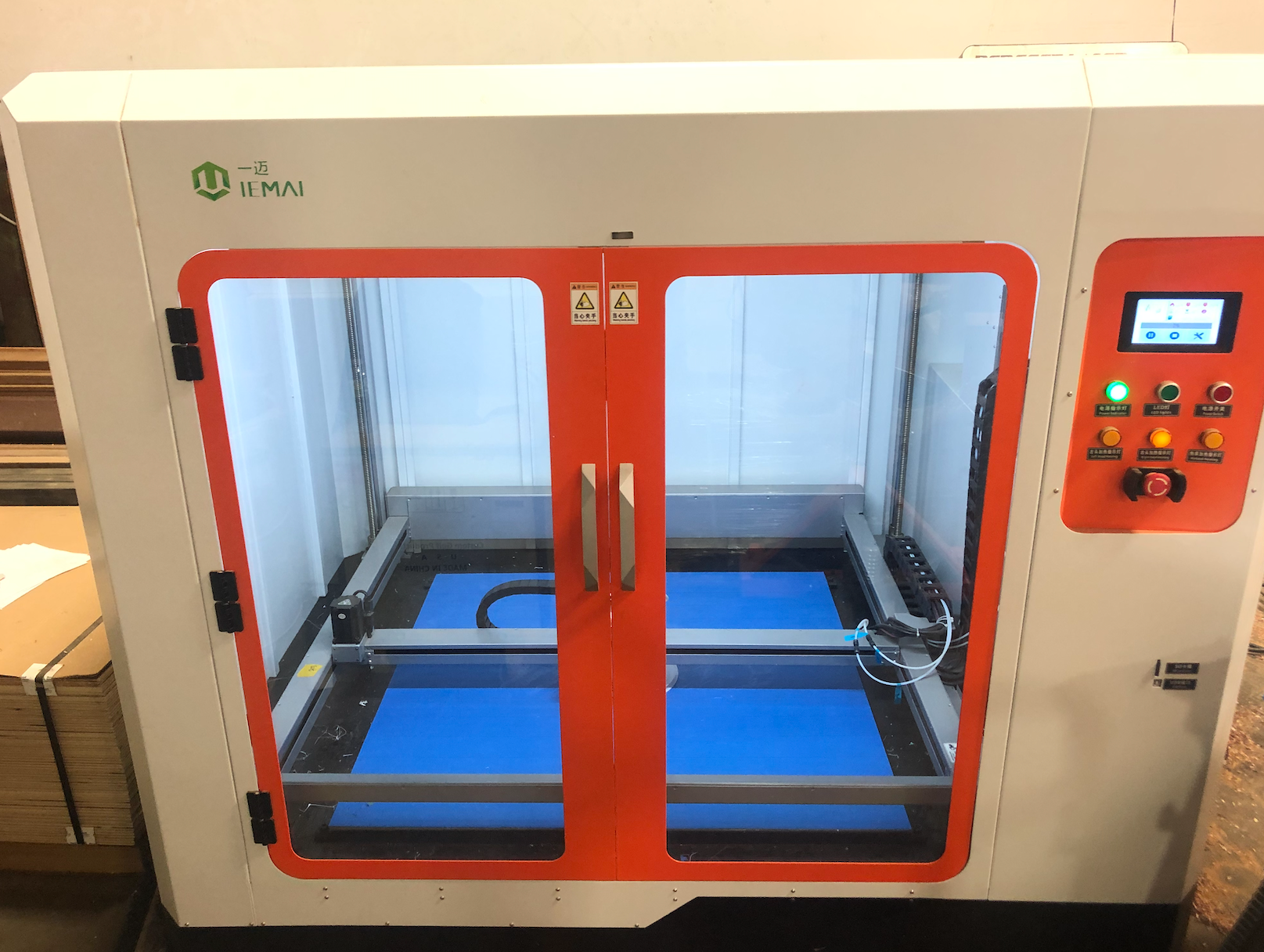
The I am using a Duet 2 Wifi with an expansion Breakout Board to control the Stepper Drivers. Those drivers and corresponding Motors are as follows:
E0 - Leadshine DM556 Driver - unbranded Nema 17 48mm x2
E1 - Leadshine DM556 Driver - unbranded Nema 17 48mm x2
X -- Leadshine CL57 Driver ----- Leadshine Easy Servo Motor D57CME21
Y -- Leadshine CL57 Driver ----- Leadshine Easy Servo Motor D57CME31
Z -- Leadshine CL86 Driver ----- Leadshine Easy Servo Motor 86CME85(for the Extruders there are 2 of these motors one for the beginning of the bowden line and one for direct drive feed)
This is my Current Config
; General preferences
G90 ; send absolute coordinates...
M83 ; ...but relative extruder moves
M550 P"Huge Printer" ; set printer name; Network
M552 S1 ; enable network
M586 P0 S1 ; enable HTTP
M586 P1 S1 ; enable FTP
M586 P2 S0 ; disable Telnet; Drives
; Drives driver direction, enable polarity and step pulse timing;-------------X MOTOR-----------
M569 P7 S0 R1 T2.5:2.5:5:10
;-------------Y MOTOR-----------
M569 P6 S0 R1 T2.5:2.5:5:10
;-------------Z MOTOR-----------
M569 P5 S0 R1 T2.5:2.5:5:10M584 X7 Y6 Z5 E9 ; set drive mapping to external drivers
M92 X183.00 Y318.00 Z1290.00 E400.00 ; set steps per mm
M566 X200.00 Y200.00 Z12.00 E120.00 ; set maximum instantaneous speed changes (mm/min)
M203 X60000.00 Y60000.00 Z180.00 E1200.00 ; set maximum speeds (mm/min)
M201 X500.00 Y500.00 Z50.00 E250.00 ; set accelerations (mm/s^2)
M906 X1000 Y1000 Z1000 E1000 I30 ; set motor currents (mA) and motor idle factor in per cent
M84 S30 ; Set idle timeout; Axis Limits
M208 X0 Y0 Z0 S1 ; set axis minima
M208 X950 Y950 Z1000 S0 ; set axis maxima; Endstops
M574 X1 Y1 Z1 S0 ; set active low and disabled endstops
;M574 X1 Y1 S0 ; X home to min. Y home to min. set active low and disabled endstops
;M574 Z1 S2 ; Define Z to use Probe. Home to Min; Z-Probe
M307 H7 A-1 C-1 D-1 ; disable heater on PWM channel 7 for BLTouch
M558 P9 H5 F100 T9000 ; set Z probe type to bltouch and the dive height + speeds
G31 P500 X-25 Y0 Z0 ; set Z probe trigger value, offset and trigger height
M557 X25:975 Y25:975 S100 ; define mesh grid; Heaters
M305 P0 T100000 B4138 R4700 ; set thermistor + ADC parameters for heater 0
M143 H0 S120 ; set temperature limit for heater 0 to 120C
M305 P1 T100000 B4138 R4700 ; set thermistor + ADC parameters for heater 1
M143 H1 S280 ; set temperature limit for heater 1 to 280C; Fans
M106 P0 S0 I0 F500 H-1 ; set fan 0 value, PWM signal inversion and frequency. Thermostatic control is turned off
M106 P1 S1 I0 F500 H1 T45 ; set fan 1 value, PWM signal inversion and frequency. Thermostatic control is turned on; Tools
M563 P0 D0 H1 F0 ; define tool 0
G10 P0 X0 Y0 Z0 ; set tool 0 axis offsets
G10 P0 R0 S0 ; set initial tool 0 active and standby temperatures to 0C; Custom settings are not defined
; Miscellaneous
M501 ; load saved parameters from non-volatile memory
M911 S10 R11 P"M913 X0 Y0 G91 M83 G1 Z3 E-5 F1000" ; set voltage thresholds and actions to run on power loss -
Y Axis loses steps on layer change. External Drivers.posted in Tuning and tweaking
Hi all,
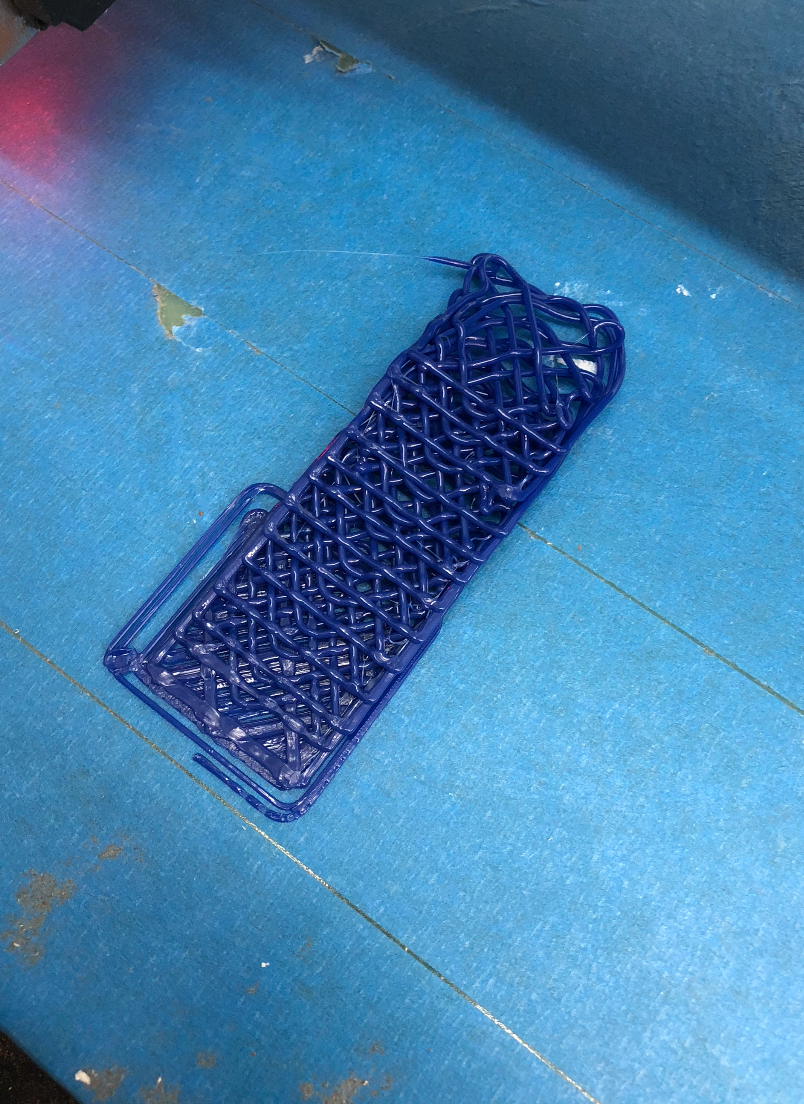
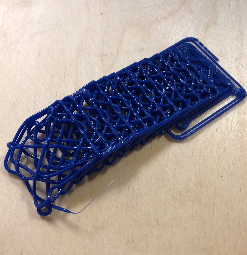
I could really use some help with an issue I am having. I just upgraded my printer to a duet wifi 2 and now when I print the Y-Axis is stepping over every layer change. Here is a picture of a simple text cube with 20% infill. can anyone tell my why this is happening or how to fix it?
-
CL57T and CL68T Stepper Driver With a Duet 2 Wifi?posted in General Discussion
Hi all,
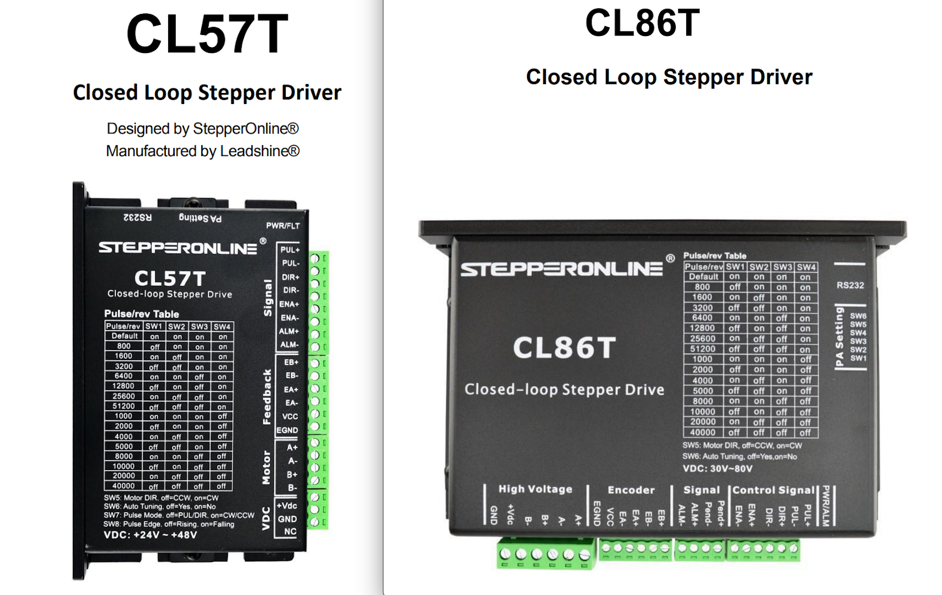
has anyone had success using a CL57T and CL68T Stepper Driver With a Duet 2 Wifi? I have a breakout board, but I am not fully Sure how to wire and configure this hardware.
I am working on converting a huge 3D printer that needs these large drivers to control the steppers that it has.
any info will help. Thanks!
-
How do I connect 220V power switch?posted in General Discussion
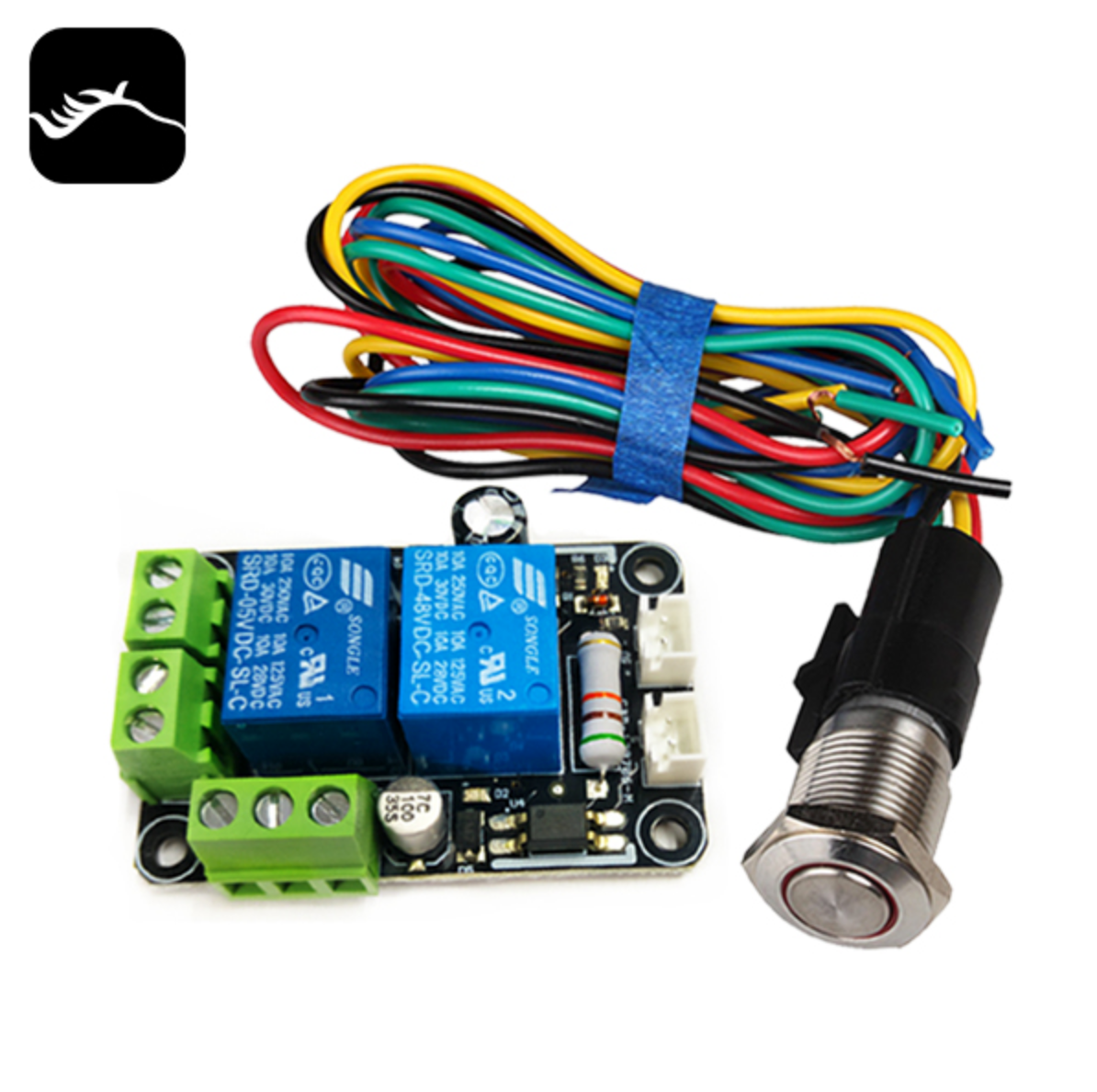
Hello, I need some help with my current project. I am converting a Chinese 3d printer to be controlled by a Duet 2 Wifi and trying to keep as many components original as possible. it originally came with this relay to control the 220V AC mains power.
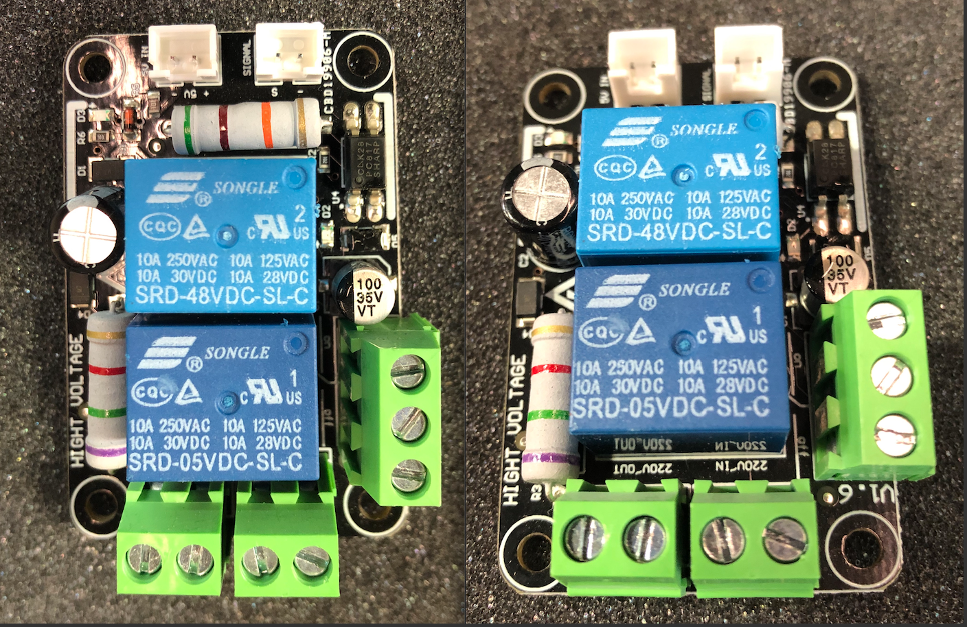
it looks like when you push the momentary switch the 220V turns on and allows power to flow to the boards and such. however if you let go of the momentary switch it stops. if i put 5V into the 5V IN on this board the 200V power is maintained. I am guessing the Signal In is to allow the Control Board to shut the machine down.

Basically how can I supply 5V DC from the Duet 2 Wifi to this board to keep it on and can I use the Signal input to control this?
-
RE: Converting a Large Chinese 3D Printerposted in Duet Hardware and wiring
Please share any help, knowledge, documentation, pictures, etc. of this sort of thing. it could really help me

-
Converting a Large Chinese 3D Printerposted in Duet Hardware and wiring
Hello All,
I am in the middle of converting a 1m x 1m x 1m large Chinese 3d Printer to have more flexibility in future upgrade in hardware and firmware. My current plan is to convert the Chitu board it currently has over to a Duet2 Wifi with a breakout board to control the stepper drivers. I am not super familiar with wiring up and creating firmware for such a large printer with odd Chinese parts. Any help with how to do this and what I should do would be great! Here is a wiring diagram of the original machine that I drew. it is incredibly complex. I'd Like to keep as much of the existing hardware as possible.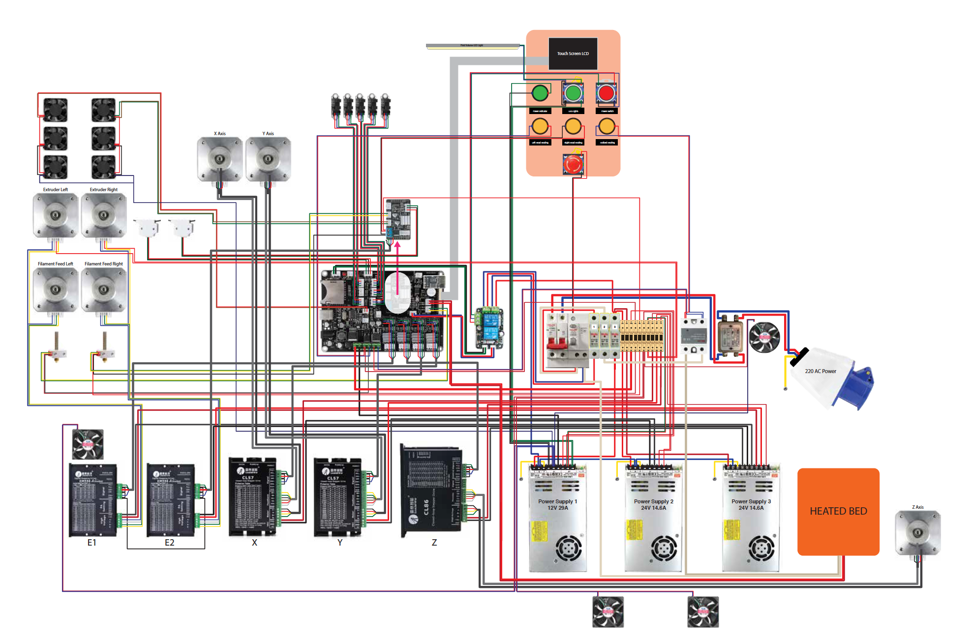 I will also attach a PDF with each components wiring separate for ease of looking at. Huge 3D Printer Wiring diagram 3.pdf