@dc42 thanks for the quick reply!
I will test it as soon as it becomes available.
Is there a reason the ratio 'Encoder counts/rev' vs 'steps/rev' has to be that high? With my current encoder I'll only get a ratio of 2:1.
research engineer at a University
@dc42 thanks for the quick reply!
I will test it as soon as it becomes available.
Is there a reason the ratio 'Encoder counts/rev' vs 'steps/rev' has to be that high? With my current encoder I'll only get a ratio of 2:1.
Hi,
I have problems getting my encoder to work.
The relevant config.g line looks like this:
M569.1 P50.0 T2 C400.0 S200.0 R100.0 I0.0 D0.0
M569 P50.0 D4 S0
This doesn't seemed to be supported by the firmware, because I get this error:
"Error in start-up file macro line 26: Encoder counts/rev must be at least four times steps/rev"
The encoder is an RLS LM10IA Linear encoder that outputs an quadrature signal. The encoder and the steps/revolution is fixed. Is there someway I can ignore the error meassage?
The purpose of the encoder is to counteract a bad/inconsistent Linear Motion System.
I know that linear encoders should be combined with a magnetic shaft encoder but why shouldn't it work standalone?
Thanks!
@t3p3tony thanks for the quick response/help!
I want to design a DIN Rail Adapter for the Duet 3 Expansion 1HCL.
A CAD-File would be helpfull, but I can't find it anywhere (not on docs.duet3d.com or github).
Am I missing something or is the file not uploaded yet?
Since I manually cool my hotend and swap it with the milling tool, I only have a post.g for tool 4:
I didn't have time to the test yet, but updating the firmware to 3.3 hasn't changed anything.
@generisi
Thanks for trying to help me out!
I'm running RFF 3.2.2 (2021-02-11).
Your first Idea seems to be the same as powering the printer down and restarting it. I do this every day and still get different results.
I'll try these 3 variations next Wednesday since I don't have access to the printer up till then.
Hopefully some of these test will reveal the reasons I'm having these problems
This is my result after homing+milling 5 times the same spot. I could't spot any difference.

I know, that this is not the center of my part, this is due to the problem with the offset of the milling tool
I know that the ASMBL is not meant for milling the whole part, thats why I'm milling very slowly.
My steps are:
I did this a few times. The gcodes for milling and printing stayed the same. I didn't copy those codes together but used them individually, as they came out of Cura and Fusion360.
The reason I did this is to dial in the offset for the milling tool. The printhead/Tool 1 has no Offset in X/Y (G10 P1 X0 Y0 Z-0.50). The offset for the milling tool right now is G10 P4 X-14.49 Y4.14 Z-17.00
At first I thought the problem was the gcode from Fusion360. So I wrote the milling-gcode by myself. But the problems stayed the same.
So my next step was to check if the toolchanging system had a problem. I printed and milled the part and then changed to the printhead again. I moved the printhead a few mm in every direction and then switched to the milling tool again. I milled the exact same part, that I milled before, again and noticed no deviation. This should mean, that my toolchanging system has no significant tolerance.
Thats when I started the tests as described above. Since my first post I have got more test/measuring results:
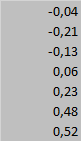
deviation in Y [mm]:
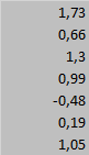
deviation in X [mm]:
I will try the test you proposed and report back with the results. But I'll still thing that homing should not matter.
@generisi i have endstops. But those should impact the tool offset.
I'm using something similar to this: https://e3d-online.com/blogs/news/asmbl
The goal is to get increase the accuracy of the dimensions of the printed part and also to improve the quality of the surface.
To adjust to offset between the printhead and the milling tool I printed this part:
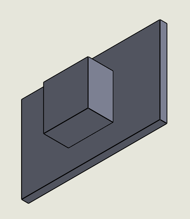
After milling it I me measured X1, X2, Y1 and Y2 (see drawing below)
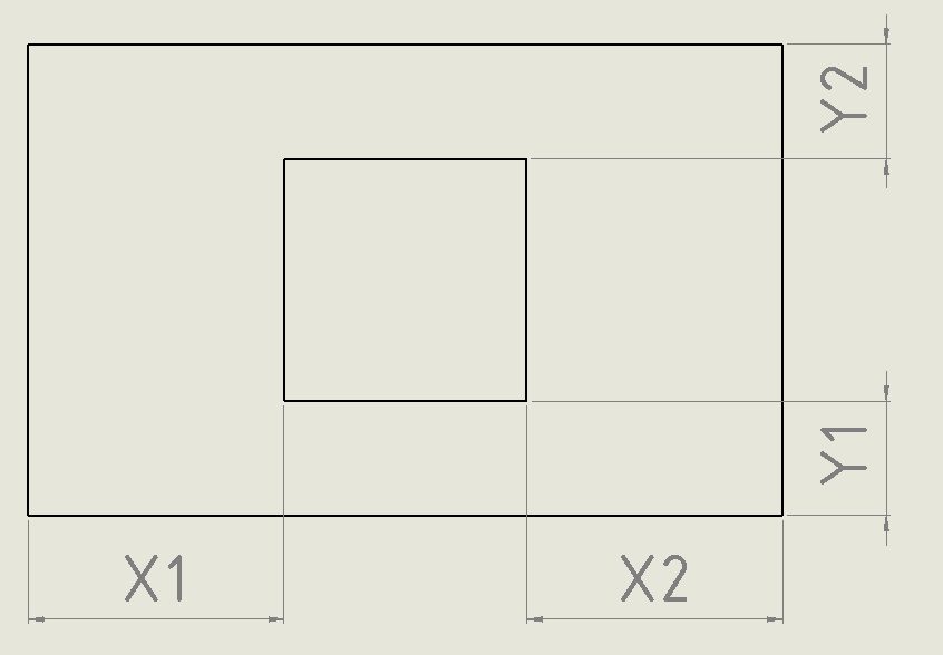
The dimensions in my first post are the difference between X1/X2 and Y1/Y2. According to the constrution of the part and the milling programm the difference should be close to 0. But it keeps changing (especially in the Y-direction).
I hope you can understand my problem better now.