Thank you so much !!
M105 reports 24.6 C which seems to be correct
I also heated it up and and cooled in back down and seems to work correctly.
Thank you so much !!
M105 reports 24.6 C which seems to be correct
I also heated it up and and cooled in back down and seems to work correctly.
Hello All,
I recently started work at a engineering firm and have been tasked with getting a large build volume 3D printer up and running.
The printer is a Ratrig Vcore-3 500 x 500 x 500 mm printer. It uses core XY architecture and has 3 lead screws for the z axis.
I am using a Duet 3 MB 6HC board. I have duet firmware 3.5.1.
I got the X and Y axis working along with the end stops.
I am trying to solve 2 issues.
I would like to know how to wire my inductive z probe. Also on the configuration tool what type of Z probe do I choose ?
How do I level the bed with 3 lead screws ? Is there any special G code command that I need to use.
Thank you for your time and support!
I have the 5V super pinda probe, I cant post a link but its on the ratrig website
But I am not sure which wire would be signal, power and ground , is there a way to test it before I plug them in ?
Also what do I choose for the Z endstop in the rrf configuration tool (Image attached)

I did read through the 3 motor levelling, is that a feature inside the rrf tool as well or do I need to write the code in the config.g and bed.g files
Thank you for your time!
Yes my board is the duet3 MB 6HC.
Thank you for your comments.
I plan to use the same power source for my heater bed as well just with a SSR which will control the AC power
Hello all,
I am trying to get my heated bed working.
I am using a SSR and controlling it using the out0 port. I have not given any power to the input of out0.
My heated bed shows up on the DWC but it does not heat up.
My question is whether I need to supply power to input of out0 for the heater bed to work ?
Thank you
Below is my config file
; General
G90 ; absolute coordinates
M83 ; relative extruder moves
M550 P"Duet 3" ; set hostname

; Network
M552 P0.0.0.0 S1 ; configure Ethernet adapter
M586 P0 S1 ; configure HTTP

; Smart Drivers
M569 P0.0 S0 D2 ; driver 0.0 goes forwards (X axis)
M569 P0.1 S0 D2 ; driver 0.1 goes forwards (Y axis)
M569 P0.2 S1 D2 ; driver 0.2 goes forwards (Z axis)
M569 P0.3 S1 D2 ; driver 0.3 goes forwards (Z axis)
M569 P0.4 S1 D2 ; driver 0.4 goes forwards (Z axis)
M569 P0.5 S0 D2 ; driver 0.5 goes forwards (extruder 0)

; Motor Idle Current Reduction
M906 I30 ; set motor current idle factor
M84 S30 ; set motor current idle timeout

; Axes
M584 X0.0 Y0.1 Z0.2:0.3:0.4 ; set axis mapping
M350 X16 Y16 Z16 I1 ; configure microstepping with interpolation
M906 X800 Y800 Z800 ; set axis driver currents
M92 X80 Y80 Z400 ; configure steps per mm
M208 X0:500 Y0:500 Z0:500 ; set minimum and maximum axis limits
M566 X900 Y900 Z12 ; set maximum instantaneous speed changes (mm/min)
M203 X6000 Y6000 Z180 ; set maximum speeds (mm/min)
M201 X500 Y500 Z20 ; set accelerations (mm/s^2)

; Extruders
M584 E0.5 ; set extruder mapping
M350 E16 I1 ; configure microstepping with interpolation
M906 E1000 ; set extruder driver currents
M92 E420 ; configure steps per mm
M566 E120 ; set maximum instantaneous speed changes (mm/min)
M203 E3600 ; set maximum speeds (mm/min)
M201 E250 ; set accelerations (mm/s^2)

; Kinematics
M669 K1 ; configure CoreXY kinematics

; Probes
M558 K0 P5 C"io2.in" H5 F120 T6000 ; configure digital probe via slot #0
G31 P500 X-28.1 Y-14.95 Z1.35 ; set Z probe trigger value, offset and trigger height

; Endstops
M574 X1 P"io0.in" S1 ; configure X axis endstop
M574 Y2 P"io1.in" S1 ; configure Y axis endstop
M574 Z1 S2 ; configure Z axis endstop

; Sensors
M308 S0 P"temp1" Y"thermistor" A"Nozzle" T100000 B4725 C7.06e-8 ; configure sensor #0
M308 S1 P"temp0" Y"thermistor" A"Heated bed" T100000 B4725 C7.06e-8 ; configure sensor #1

; Heaters
M950 H0 C"out1" T0 ; create heater #0
M143 H0 P0 T0 C0 S285 A0 ; configure heater monitor #0 for heater #0
M307 H0 R2.43 D5.5 E1.35 K0.56 B0 ; configure model of heater #0
M950 H1 C"out0" T1                ; create heater #1
M143 H1 P0 T1 C0 S140 A0          ; configure heater monitor #0 for heater #1
M307 H1 R2.43 D5.5 E1.35 K0.56 B0 ; configure model of heater #1

; Heated beds
M140 P0 H1                        ; configure heated bed #0

; Fans
M950 F0 C"out4+out4.tach" ; create fan #0
M106 P0 S0 L0 X1 B0.1     ; configure fan #0
M950 F1 C"out2"           ; create fan #1
M106 P1 S0 B0.1 H0 T45    ; configure fan #1

; Tools
M563 P0 D0 H0 F0 ; create tool #0
M568 P0 R0 S0 ; set initial tool #0 active and standby temperatures to 0C

; bed leveling stuff
M584 X0.0 Y0.1 Z0.2:0.3:0.4 E0.5 ; three Z motors connected to driver 2 (front left), driver 3 (rear middle) and driver 4 (front right)
M671 X-46:250:551 Y-11:557:-11 S0.5 ; position of leadscrew/bed pivot point at front left, rear middle and front right
M208 X0:500 Y0:500 ; X carriage moves from 0 to 500, Y bed goes from 0 to 500
thank you so much for your response!
I assume the same is true for Out 2 for Fan 1 where V fused is +ve 24 v and out 2 is -ve.
Thanks again!
Hello,
I am using a Duet 3 MB 6HC to control my 3D printer and am in the process of wiring the machine and getting things working.
I have read the documentation on wiring fans but I have a few questions still.
I need to wire a part cooling fan which is Fan 0 and a cooling fan for the hotend which is Fan 1. Fan1 can be linked to the thermistor of the nozzle.
I am using a 24 V power source.
For wiring Fan 0 which is a 12 V fan I plan to use out_4. My fan has a 2 wires. My jumper pins have 12 v and the center pin connected for out_4 to out_6.
Can I connect the red wire of fan to V_outlc1 or to out4? what's the difference between those two pins?
Attached image of the board below.
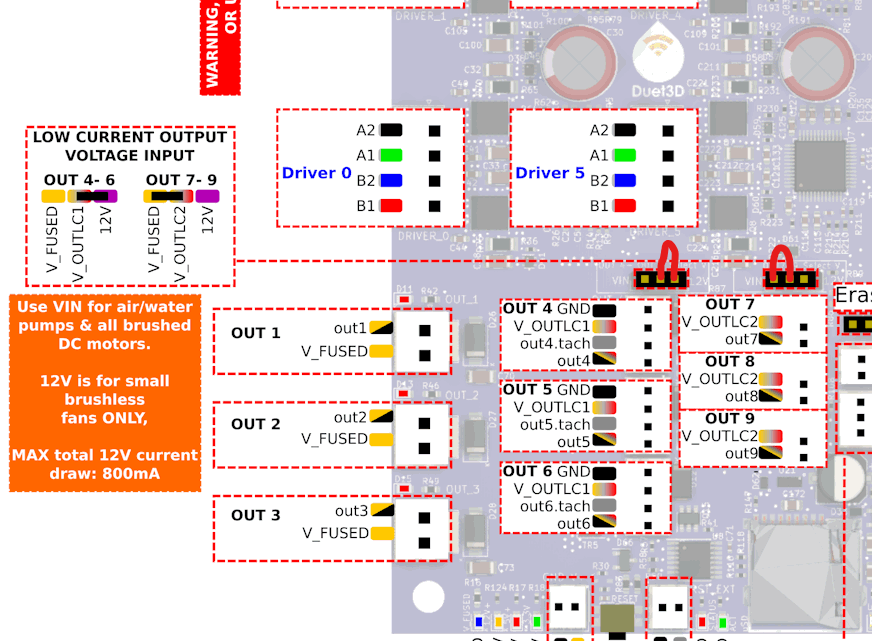
For my Fan 1 which is 24 V fan I plan to use out_2. This fan is also 2 wired. I plan on having the red wire connected to V_fused and the black one to out2. is that the correct way to wire the fan ?
Thank you for your help!
My X, Y and Z axis are moving in the correct direction.
When I home the z axis the X and Y axis move to the 0,0 position which shifts the inductive probe off the bed. I was trying to have the X and Y axis at 250 , 250 mm when Z was homing.
I have modified the homez.g and homeall.g files and it seems to working fine for now, I have not tried to print anything yet.
Regarding bed leveling:
Do I need to know the position of the lead screw ? cause I did not design the machine so its hard for me to know where the lead screw would be.
A question I have regarding leveling the bed:
Do I need to know the position of the lead screw itself with respect to the origin.
below is a piece of code from the instructions
M671 X-15:100:215 Y-10:190:-10 S0.5 ; position of leadscrew/bed pivot point at front left, rear middle and front right
How would I be able to tell the position of the lead screws if I did not design the machine?
for now I have manually changed the homez.g file to look like this
; home Z
var xCenter = move.compensation.probeGrid.mins[0] + (move.compensation.probeGrid.maxs[0] - move.compensation.probeGrid.mins[0]) / 2 - sensors.probes[0].offsets[0]
var yCenter = move.compensation.probeGrid.mins[1] + (move.compensation.probeGrid.maxs[1] - move.compensation.probeGrid.mins[1]) / 2 - sensors.probes[0].offsets[1]
;G1 X{var.xCenter} Y{var.yCenter} F6000 ; go to bed centre
G1 X250 Y250 F6000
G30 ; probe the bed
and it seems to work file
I will do the same to the homeall.g file as well.
Does G28 call the homeall.g file ?
I just got it working using the digital mode
M558 K0 P5 C"io2.in" H5 F120 T6000
I changed p3 to p5 and its working,
the issue I am having now is that while homing the head goes to 0,0 position on the x and y and this pushes the probe outside the bed.
Is there a way I can tell the head to move to a center location. i know its in the forums somewhere but I am digging to find it .
This is the code from my home z
; homez.g
; called to home the Z axis
;
; generated by RepRapFirmware Configuration Tool v3.5.10 on Thu Mar 06 2025 13:28:18 GMT-0500 (Eastern Standard Time)

; increase Z
G91 ; relative positioning
G1 H2 Z5 ; move Z relative to current position to avoid dragging nozzle over the bed
G90 ; absolute positioning

; home Z
var xCenter = move.compensation.probeGrid.mins[0] + (move.compensation.probeGrid.maxs[0] - move.compensation.probeGrid.mins[0]) / 2 - sensors.probes[0].offsets[0]
var yCenter = move.compensation.probeGrid.mins[1] + (move.compensation.probeGrid.maxs[1] - move.compensation.probeGrid.mins[1]) / 2 - sensors.probes[0].offsets[1]
G1 X{var.xCenter} Y{var.yCenter} F6000 ; go to bed centre
G30 ; probe the bed
the line above G30 does tell the head to go to the center so I dont know why it goes to 0,0 unless it thinks thats the center
maybe I can add offsets in the config.g file
")