@dc42 @droftarts thank you again! I'll get back to experimenting and will post an update on my progress.
Posts made by Jords27
-
RE: Roto toolboard extra fansposted in Duet Hardware and wiring
-
Roto toolboard extra fansposted in Duet Hardware and wiring
Hello everyone,
I was wondering if it would be possible to add an extra fan to the Roto Toolboard? I have already used up OUT_1 and OUT_2, but I’m considering adding an extra driver circuit on IO_0_OUT to connect another fan. Would this be feasible or is there another option?
Additionally, I’m exploring the use of only 4-wire fans. Would it be possible to connect the tachometer and PWM signals from such a fan to OUT2 on the Roto Toolboard, while powering the fan from an external source?
Thank you all in advance for your help!
-
RE: Uploading bootloader and firmware using Atmel Studioposted in Firmware installation
@dc42 Thank you again for your help. It took a while but we figured out that the external oscillator was not producing the correct frequency. After replacing the oscillator with another model everything was working as expected!
-
RE: Uploading bootloader and firmware using Atmel Studioposted in Firmware installation
@dc42 and @gloomyandy thank you again for your help, experimenting with this has been fun and insightfull.
It has been a while but last week I tried uploading the roto toolboard firmware to a devboard with the same MCU as the roto toolboard. I select the Atmel-ICE and ATSAME51G19A, and am then able to get the correct device signature and 3.3V as the Target Voltage. I upload the bootloader to 0x0 and after that the TOOL1RR firmware to 0x10000. Doing al this I don't get any errors. I would assume that after doing that the devboard "thinks" it is a roto toolboard but when connection it to a 6hc mainboard there isn't any sign of life. I have also tested this method on a completely whiped Roto Toolboard. This seemed to work because the Roto Toolboard worked just as expected after. Would you or someone else know if I could be missing something?
Thanks to everyone again on this forum, everyone here is always awesome!
-
RE: Optocoupler in Roto Toolboardposted in Duet Hardware and wiring
@dc42 Thank you, that makes sense!
-
Optocoupler in Roto Toolboardposted in Duet Hardware and wiring
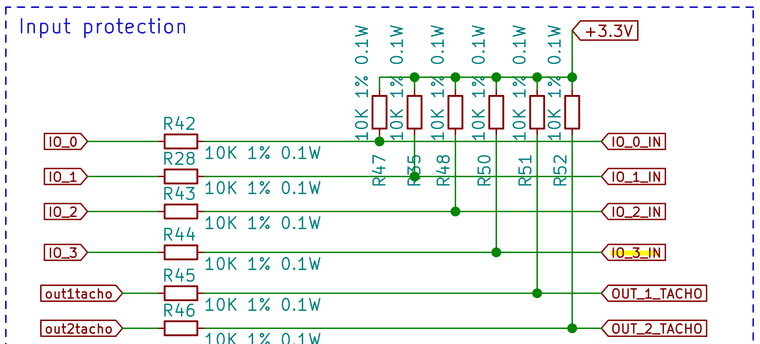
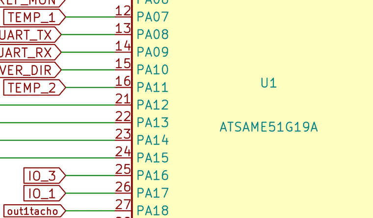
Hello everyone. I was looking at the Roto Toolboard schematic and saw that IO3 isn't routed to a connector. It is routed the same way as the other IO pins, but where the other IO pins route to a connector, IO_3_IN is connected to GND through an optocoupler. The optocoupler is continuously activated by the 3.3V supply. Wouldn't that then mean that IO_3_IN is continuously pulled to GND?
Thank you all in advance once again.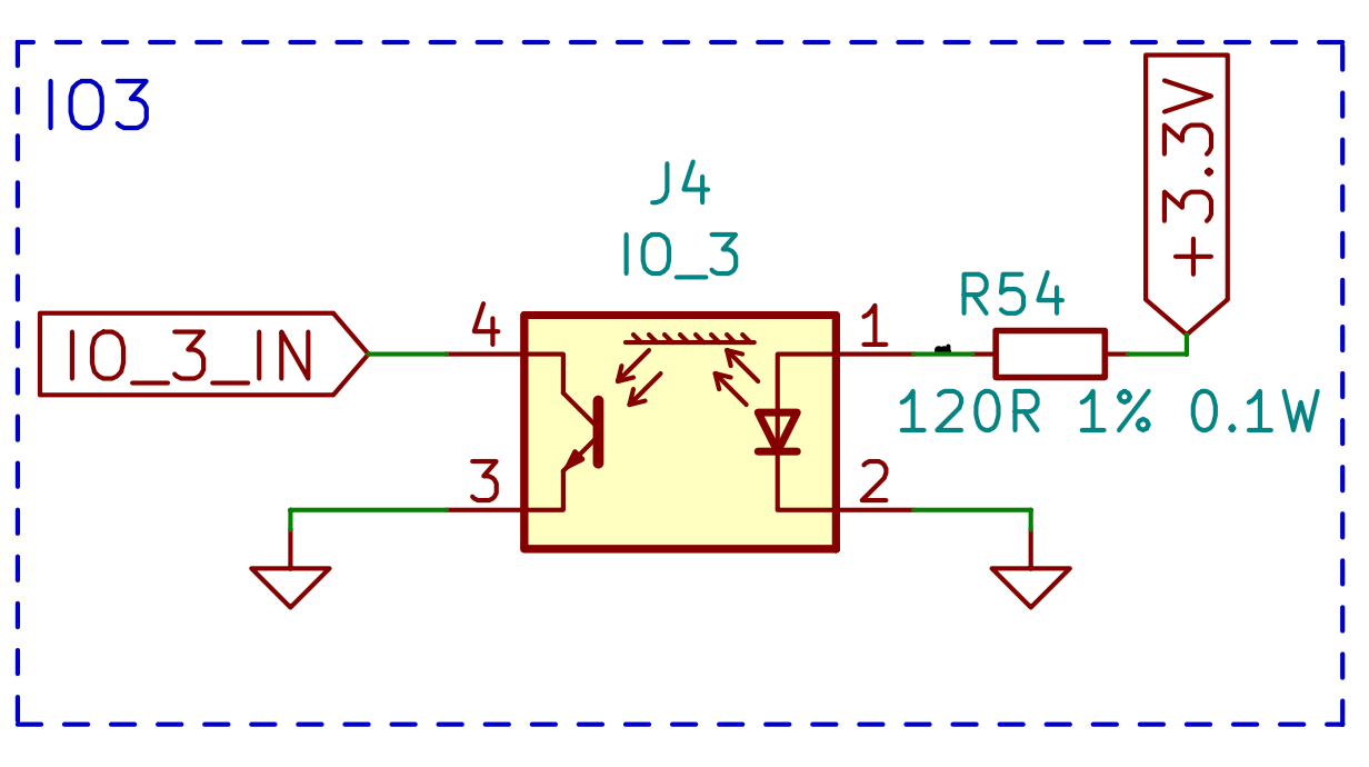
-
RE: Uploading bootloader and firmware using Atmel Studioposted in Firmware installation
@gloomyandy Thanks for your response. I accidentally tried uploading to the user page once, but it just remained there. If I upload the bootloader first, followed by the firmware, how can I ensure that the bootloader is not erased in the process?
-
Uploading bootloader and firmware using Atmel Studioposted in Firmware installation
Re: Help updating bootloader with Atmel-ICE
Hello everyone,
I saw the topic mentioned above, and I am working on something similar. I am trying to program an Adafruit Feather M4 CAN Express with the "Duet3Bootloader-SAME5x.bin" file and a modified version of the Roto Toolboard and EXP3HC firmware. I am using Atmel Studio and an Atmel-ICE for this task. Are specific programming addresses required for flashing the bootloader and firmware?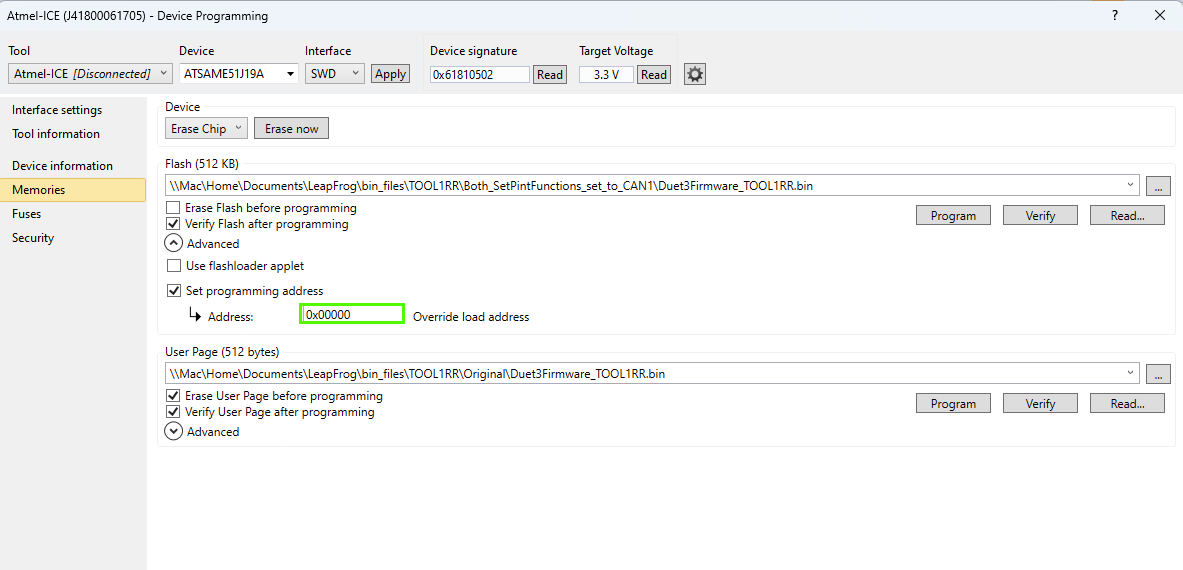
-
RE: barebones expansion firmwareposted in Firmware installation
@chrishamm and @dc42, thank you for your responses. I have not flashed the bootloader. When I upload the firmware, nothing seems to happen. When I upload the .bin file for the TOOL1RR board, nothing seems to happen, but when I upload a basic project controlling an LED using the same method, it does work. I have tried changing the pin declaration for CAN and changing UseAlternateCanPins = true to false, but that also didn't work. After that, I tried setting a pin high in the Platform::Init() function in Platform.cpp, and that also didn't do anything. I am now thinking that something else might be wrong, but I have not yet figured out what. I will keep looking into it and will let you know when I have figured it out.
-
barebones expansion firmwareposted in Firmware installation
I am trying to develop a custom expansion board for the Duet mainboard using the CAN-FD bus. Is there some barebones firmware available for something like the Roto Toolboard?
Currently, we are trying to modify the Roto Toolboard firmware to work on an Adafruit Feather M4 CAN but have not yet succeeded in communicating with the 6HC mainboard. The Feather uses the 64-pin version of the same IC as the Roto Toolboard. Since the Feather uses different pins for connecting to the CAN transceiver, we have tried to alter SetPinFunction in CanInterface.cpp, but that also didn't work. It doesn't produce any errors, but the Feather just doesn't start communicating after the firmware has been uploaded. If someone has a tip, that would be awesome; anything could be helpful at this stage.
-
RE: RepRapFirmware on Adafruit Feather M4 CAN Expressposted in Firmware installation
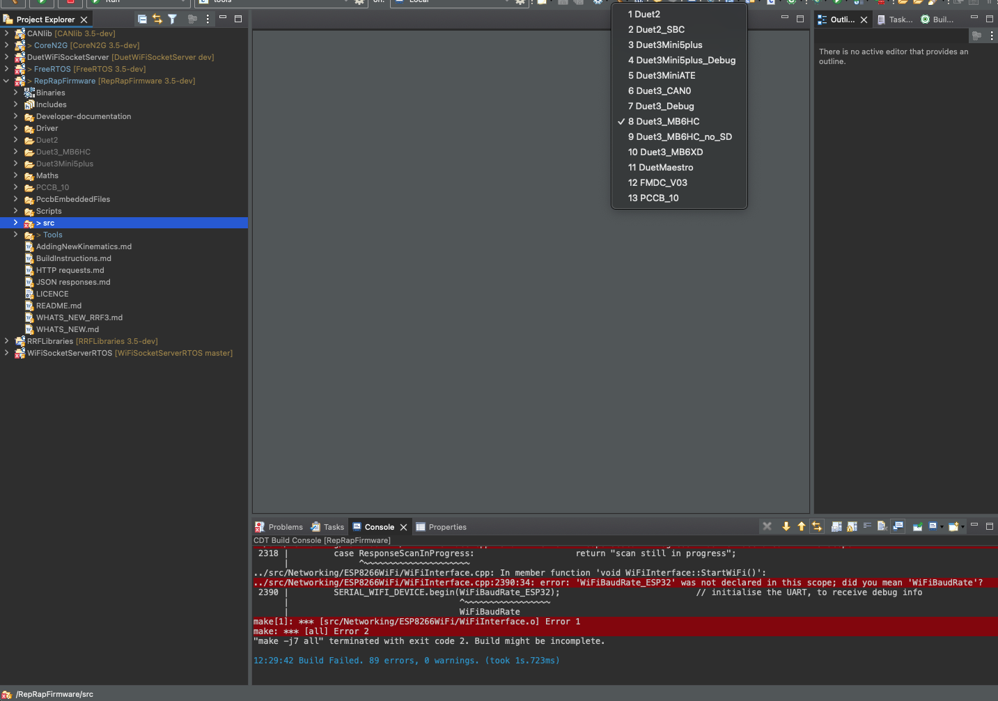
I also still get those wifi errors when building for the DUET3_MB6HC as shown in the picture so does somewone know how to resolve that?
-
RE: RepRapFirmware on Adafruit Feather M4 CAN Expressposted in Firmware installation
@chrishamm Thank you for your response. I have looked at that github page and followed of those steps. Unfortunately I haven't been able to find the Duet3Expansion repo. If you or somewone else could show me then that would be awesome.
-
RepRapFirmware on Adafruit Feather M4 CAN Expressposted in Firmware installation
Hello everyone,
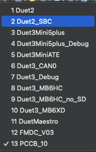
I am trying to deepen my understanding of the DUET3D firmware. I would like to be able to put the RepRapFirmware on an Adafruit Feather M4 CAN Express and communicate through the can bus with the rest of the DUET3D ecosystem. Just like the Duet 3 Roto Toolboard the Feather M4 also has an ATSAME51 so I thought I would be able to put that firmware on the Feather. When building the Firmware I just can't find the option to build for the Roto Toolboard. Is there an option for that somewere else or is It not an option?
My second question is that when I try to build the firmware for example for the DUET3_MB6HC I get multiple wifi related errors. Is there something I can do to resolve this?
thank you in advance!
-
RE: Function of two can busses.posted in Duet Hardware and wiring
@droftarts Thanks for that response, that is really helpful!
-
Function of two can busses.posted in Duet Hardware and wiring
I am developing specific hardware for the DUET using the can-fd protocol. I just can't figure out why most of the DUET board have two can connections with 4 wires? I have also seen that the Duet 3 Roto Toolboard has just one can connection with 2 wires. In the can basisc documentation I found that just can1 is used for now and that CAN0 is for future expansion. Are the can0 wires just not active?