Thank you very much for your time! 
That did the trick.
I needed a normaly open switch so there is no connection between the wires when the filament is loaded.
kind regards,
Leon.
Thank you very much for your time!
That did the trick.
I needed a normaly open switch so there is no connection between the wires when the filament is loaded.
kind regards,
Leon.
Hi to you all,
I'm using firmware version:
FIRMWARE_NAME: RepRapFirmware for Duet 2 WiFi/Ethernet FIRMWARE_VERSION: 2.0(RTOS) ELECTRONICS: Duet Ethernet 1.02 or later FIRMWARE_DATE: 2018-06-05b3
I have connected a simple switch with two leads going to the E0-stop on the ground and the signal pin.
I have put a piece of filament in de sensor housing gausing the switch to be closed.
In de config.g I have:
; Endstops
M574 X1 Y1 Z0 E1 S0
; Filament runout sensor
M591 D1 P1 C3
With a M119 the E-stop does not show up.
What am I doing wrong?
regards,
Leon.
Found the solution already by using a typical Homez.g file for a probe.
G91 ; relative mode
G1 S2 Z4 F200 ; raise head 4mm to ensure it is above the Z probe trigger height
G90 ; back to absolute mode
G1 X100 Y100 F2000 ; put head over the centre of the bed, or wherever you want to probe
G30 ; lower head, stop when probe triggered and set Z to trigger height
Thanks for the help!!
Kind regads,
Leon
@dc42
Yes thank you very much that did the job!
Instructions followed and they work now.
But please hang on with me.
I want to set the probing grid but have problems with the Z-homing. The sensor does not respond and the nozzle hits the build plate.
Must be something wrong in the homez.g
Firmware Name: RepRapFirmware for Duet 2 WiFi/Ethernet
Firmware Electronics: Duet Ethernet 1.02 or later
Firmware Version: 2.0(RTOS) (2018-06-05b3)
Web Interface Version: 1.19.3
; Endstops
M574 X1 Y1 Z2 S0 ; Set active low endstops
; Z-Probe
M558 P1 H2 F120 T6000 ; Set Z probe type to switch and the dive height + speeds
G31 P500 X0 Y0 Z0.390 ; Set Z probe trigger value, offset and trigger height
;M557 X60:700 Y60:400 S20 ; Define mesh grid
M557 X0:200 Y0:220 S20
; homez.g
; called to home the Z axis
;
; generated by RepRapFirmware Configuration Tool on Thu Oct 04 2018 14:52:24 GMT+0200 (Midden-Europese zomertijd)
G91 ; relative positioning
G1 Z5 F10 S2 ; lift Z relative to current position
G1 S1 Z-100 F500 ; move Z down until the endstop is triggered
G92 Z5 ; set Z position to axis minimum (you may want to adjust this)
; Uncomment the following lines to lift Z after probing
;G91 ; relative positioning
;G1 S2 Z5 F100 ; lift Z relative to current position
;G90 ; absolute positioning
I'm back with a brand-new Duet Ethernet board and a new Ir-sensor. Ir sensor is flashing 4 times when starting up.
I followed all the instruction several times over here but for some reason it does not work. Constantly getting the message after send "M558 P1 and G31 P500 Z1.0"
"G30 S-1
Error: Z probe already triggered at start of probing move"
Even when sensor is way up like 15 cm.
Reading is 1000 sensor way up, getting closer and touch the sensor reading 461?!
sensor lids red when touching
M119
Endstops - X: not stopped, Y: not stopped, Z: not stopped, Z probe: at min stop
here a piece of my config.g where probably something is wrong
config.g
; Drives
M569 P5 S1 R1 T1 ;Y-as
M569 P6 S0 R1 T1 ;X-as
M569 P7 S0 R1 T4 ;Z-as
M584 X6 Y5 Z7 E3 ; Apply custom drive mapping
M564 S0 H0
M350 X8 Y8 Z8 E8 I1 ; Configure microstepping with interpolation
M92 X125.98 Y125.98 Z500 E495 ; Set steps per mm
M566 X300 Y300 Z50 E120 ; Set maximum instantaneous speed changes (mm/min)
M203 X5000 Y5000 Z500 E500 ; Set maximum speeds (mm/min)
M201 X200 Y200 Z50 E100 ; Set accelerations (mm/s^2)
M906 X7200 Y7200 Z4000 E800 I30 ; Set motor currents (mA) and motor idle factor in per cent
M84 S50 ; Set idle timeout
; Axis Limits
M208 X0 Y0 Z0 S1 ; Set axis minima
M208 X700 Y400 Z100 S0 ; Set axis maxima
; Endstops
M574 X1 Y1 Z2 S0 ; Set active low endstops
; Z-Probe
M558 P1 I1 H2 F120 T6000 ; Set Z probe type to switch and the dive height + speeds
G31 P500 X0 Y0 Z0 ; Set Z probe trigger value, offset and trigger height
M557 X60:700 Y60:400 S20 ; Define mesh grid
; bed.g
; called to perform automatic bed compensation via G32
;
; generated by RepRapFirmware Configuration Tool on Thu Oct 04 2018 14:52:24 GMT+0200 (Midden-Europese zomertijd)
M561 ; clear any bed transform
; Probe the bed at 4 points
G30 P0 X60 Y60 H0 Z0
G30 P1 X60 Y400 H0 Z0
G30 P2 X750 Y400 H0 Z0
G30 P3 X750 Y60 H0 Z0
; homez.g
; called to home the Z axis
;
; generated by RepRapFirmware Configuration Tool on Thu Oct 04 2018 14:52:24 GMT+0200 (Midden-Europese zomertijd)
G91 ; relative positioning
G1 Z5 F10 S2 ; lift Z relative to current position
G1 S1 Z-100 F500 ; move Z down until the endstop is triggered
G92 Z0 ; set Z position to axis minimum (you may want to adjust this)
; Uncomment the following lines to lift Z after probing
;G91 ; relative positioning
;G1 S2 Z5 F100 ; lift Z relative to current position
;G90 ; absolute positioning
I hope it is a simple fault. I'm almost there to get this printer working, dealing with the frustration the nozzle has crashed several times into the build plate and the heat brake is broken now 
I made a terrible mistake. Not looking good I plugged the signal wire from the IR probe into the UTXD0 pin.
When starting up de wire begon to smoke intens. No connection possible with the board anymore using ethernet consol to a PC. Also no cnnection with LCD 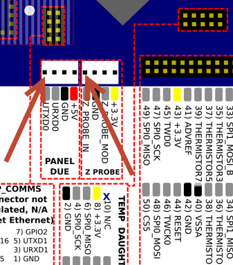
Is there some information available what is really damaged or do I have to replace the whole board. Seems like a chip on de little ethernet board is fried? 2 of the steppermotors make a load buzzing noise to. O boy!

Thanks!, that what I think too. I will go to my supplier.
In the control panel there is a distance probe reading like the 465 and 535.
After I zero the nozzle tip to the buildplate with G92 Z0
I entered the G30 S-1 after going 5mm up.
I get a reading of 1.15mm so I asume the sensor is triggering something?
I remembered I did not connect the board first with USB but ride away using
the ethernet cable. Could that be the reason for not flashing the led's?
Hello to you all,
Connected the IR probe version 1.3 to the board (Duet Ethernet) and when powered on there is no flashing of the leds at all.
I have measured the VCC+ en ground on the little board and there is 3.3v. Also measured if the signal lead is connected to the main board with an ohm meter and that is also fine. The probe does respond to the surface but when probing to all the points, there is no flashing and If got the message "Z probe was not triggered during probing move". Looks like the there is something wrong with the IR-probe board. What can I do. Wires to the probe are quite long around 3 meters.
kind regards,
Leon.
To complete this thread for others. I had to use the 5v connection from the breakout board to make the DM556 to work properly. For some reason the 3.3v voltage from the +signals ENA PUL and DIR does not do the job for this driver.
@dc42
The TB6600 stepper driver seems to be not a suitable driver for the duet.
This week arrived the DM556 drivers and they work without any problems.
Thanks for all the help!
Kind regards,
Leon.
My problem is still not solved. If there are no options left over please let me know.
I will trow this well developed board out of the window and never look at it again.
After a reset off everything I measure this -3.53v
After pushing the y move button the voltage change to plus +3.53v
The led down under is bright all the time
The led above is pulsing when pushing the move button.
Same measurement on the breakout board self without stepper driver connected.

@dc42 said in Breakout board produces no 5v signals:
M569 P5 R1 T2
No, sorry no results. Second led is pulsing but it seems there is no current at all to drive the motor.
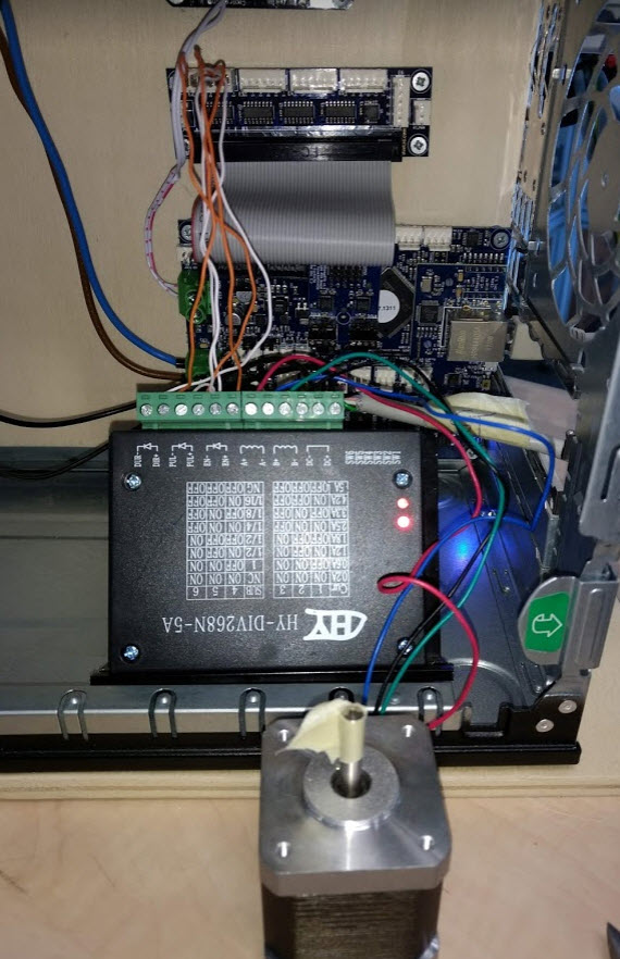
Extra info: the stepper driver has a 48v dc connection
The attached motor is a standard nema 17 to see if it works (must be later on a nema23)
; Drives
M569 P0 S1 ; Drive 0 goes forwards
;M569 P1 S1 ;does not work
;M569 P5 S0 ;does not work
;M569 P5 R1 ;does not work
;M569 P5 R1 T1 ;does not work
;M569 P5 R1 T2 ;does not work
;M569 P5 R1 T5 ;does not work
;M569 P5 R0 T2 ;does not work
M569 P5 R0 T4 ; does not work
M569 P2 S1 ; Drive 2 goes forwards
M569 P3 S1 ; Drive 3 goes forwards
M584 X0 Y5 Z2 E3 ; Apply custom drive mapping
M564 S0 H0
@adavidm
Yes I have changed P1 to P5 and nothing.
I thought the drive mapping should do the job but I understand you have to assign the drive (on the break out board) in the M569 also.
Here the specs if this is what you need for the TB6600.
The stepperdriver is connected to a 48v dc powersupply.
Specification
Input Current: 0~5A
Output Current: 0.5~4.0A
Control Signal 3.3~24V
Power (MAX): 160W
Micro Step:1, 2/A, 2/B, 4, 8, 16, 32
Temperature: -10~45℃
Humidity:No Condensation
Weight: 0.2 kg
Dimension: 96 * 71 * 37 mm
Or a link to this wiki here
Please explain how I can switch to 5v, Is there somebody out there who have done this.
Thanks for the help.
regards,
Leon.
@dc42 said in Breakout board produces no 5v signals:
M569 P1 R1 T3
Thanks for the help but it did not work.
I have tried all these settings also on P1.
; Drives
M569 P0 S1 ; Drive 0 goes forwards
;M569 P1 S1 ;does not work
;M569 P5 S0 ;does not work
;M569 P5 R1 ;does not work
;M569 P5 R1 T1 ;does not work
M569 P5 R1 T2 ;does not work
M569 P2 S1 ; Drive 2 goes forwards
M569 P3 S1 ; Drive 3 goes forwards
M584 X0 Y5 Z2 E3 ; Apply custom drive mapping
M350 X16 Y16 Z16 E16 I1 ; Configure microstepping with interpolation
M92 X80 Y80 Z4000 E420 ; Set steps per mm
M566 X900 Y900 Z12 E120 ; Set maximum instantaneous speed changes (mm/min)
M203 X6000 Y6000 Z180 E1200 ; Set maximum speeds (mm/min)
M201 X500 Y20 Z250 E250 ; Set accelerations (mm/s^2)
M906 X800 Y5000 Z800 E800 I30 ; Set motor currents (mA) and motor idle factor in per cent
M84 S60 ; Set idle timeout
De second LED on de stepperdriver flashes like it is pulsing, but there is no movement in de stepper motor at all.
Set the current on the stepper driver from 1 to 5 amp but no effect. Current in de config is set to 5000.
Please help me out I don't want to struggle another day ")
regards,
Leon.
I'm trying to drive an External stepper driver using the breakout board on a new Duet Ethernet. I assuming the signals from the board will be boost up from 3.3 to 5v but I'm afraid I misunderstood. When I measure with a multimeter there's 3.3v DC on the dir+ and dir- and en+ and en- when idle. When I try to move the y-axes there appears hardly no voltage on the pul+ and pul- signal. I want to drive a Nema 23 but for testing purposes I hooked up an Nema17. No movement at all. My external driver is a TB6600 see picture below and hier a piece of my config:
; Drives
M569 P0 S1 ; Drive 0 goes forwards
;M569 P1 S1 ; Drive 1 goes forwards
M569 P1 R1 T3
M569 P2 S1 ; Drive 2 goes forwards
M569 P3 S1 ; Drive 3 goes forwards
M584 X0 Y5 Z2 E3 ; Apply custom drive mapping
M350 X16 Y16 Z16 E16 I1 ; Configure microstepping with interpolation
M92 X80 Y80 Z4000 E420 ; Set steps per mm
M566 X900 Y900 Z12 E120 ; Set maximum instantaneous speed changes (mm/min)
M203 X6000 Y6000 Z180 E1200 ; Set maximum speeds (mm/min)
M201 X500 Y20 Z250 E250 ; Set accelerations (mm/s^2)
M906 X800 Y5000 Z800 E800 I30 ; Set motor currents (mA) and motor idle factor in per cent
M84 S60 ; Set idle timeout
What can I do to boost up the signal to 5v if that's the problem.
I'm stuck on this way to long so any help would be great.
Kind regards,
Leon.
I received a new duet wifi and everything works fine. The sd card reader was not functioning.
In an other thread new problems with the router I used. The card is fine.
@phaedrux
I used an old wifi router that I had laying around at home. It worked fine with the Duet, but then many colleagues began to complain about the bad wifi. It was my router so I had to turn it down.
I don't know what will happen if I turn the duet into access point mode but I will try. I assume a duet as an access point will cause the same problems? The duet acts like a wifi-router?