@dc42 In a closed loop, D is 0, and still, for a 0.8 nozzle, I tend to run at 30-40 mm/s, and at that speed, it is very noisy. The assisted open loop leads to shifts. Unfortunately, these parts are in production, and I just went back to open loop with reduced Acceleration and higher motor current. We will deal with the setup after this job is finished
Posts made by martin7404
-
RE: Plan to switch from normal steppers to 1HCL+ magnetic encodersposted in Using Duet Controllers
-
RE: Plan to switch from normal steppers to 1HCL+ magnetic encodersposted in Using Duet Controllers
@martin7404 From time to time, it pauses due to these errors, and when I resume,e there is a slight layer shift
For now, for the big nozzle, I am switching to open loop with high current on the motors.
And will use a closed loop when printing with a smaller nozzle
May be in the future I will switch the motors to 1.8 and will test tuning them again -
RE: Plan to switch from normal steppers to 1HCL+ magnetic encodersposted in Using Duet Controllers
@dc42 Everything works but with 0.8 nozzle, I have to run pretty slow and there is too much vibration in closed-loop mode, so I switched to assisted open loop
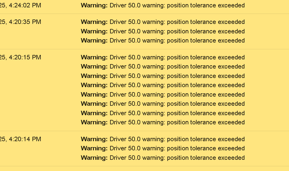
I get a lot of these
Do you mean R value in M569.1 ? -
RE: Klicky probe configposted in Duet Hardware and wiring
@Dad003 But the wiring is the same as using a regular stop switch . And the solder jumper is well described in klicky documentation
-
RE: Klicky probe configposted in Duet Hardware and wiring
@Dad003 Can you share photos of your klicky? Is it PCB klicky? There is a solder "jumper " to switch 5 V to 24 V circuit on PCB clicky
I had made this mistake, and for some reason, it worked ok and, in one moment, started to be intermittent until I found my mistake. Also, I would suggest using 5V and not 3.3 power
Please share info and we can help further.
I have Klicky setup and running on both Duet wifi and Duet 3 with tool board -
RE: Plan to switch from normal steppers to 1HCL+ magnetic encodersposted in Using Duet Controllers
the final config.g
; Configuration file for Duet 3 (firmware version 3) ; executed by the firmware on start-up ; ; generated by RepRapFirmware Configuration Tool v3.2.3 on Thu May 27 2021 13:17:12 GMT+0300 (Eastern European Summer Time) ; General preferences G90 ; send absolute coordinates... M83 ; ...but relative extruder moves M550 P"CoreXY500" ; set printer name M669 K1 ; select CoreXY mode ; Network M552 P192.168.1.27 S1 ; enable network and acquire dynamic address via DHCP M586 P0 S1 ; enable HTTP M586 P1 S0 ; disable FTP M586 P2 S0 ; disable Telnet G4 S2 ;wait for expansion boards to start ; Drives M569.1 P50.0 T3 E4:8 S400 R40 I1500 D0.05 V400 A200000 H10 ; Configure the Duet 3 Expansion 1HCL board at CAN address 50 with a Duet 3 magnetic encoder, warn if 1 fullstep threshold exceeded, error if 2 full steps threshold exceeded. M569 P50.0 D4 S1 ; ;M569 P0.0 S1 ; physical drive 0.0 goes forwards ;M569 P0.1 S0 ; physical drive 0.1 goes forwards M569.1 P51.0 T3 E4:8 S400 R40 I1500 D0.05 V400 A200000 H10 ; Configure the Duet 3 Expansion 1HCL board at CAN address 50 with a Duet 3 magnetic encoder, warn if 1 fullstep threshold exceeded, error if 2 full steps threshold exceeded. M569 P51.0 D4 S0 M569 P0.3 S0 M569 P0.4 S1 M569 P0.5 S1 ; physical drive 0.2 goes forwards M569 P121.0 S1 ; physical drive 121.0 goes forwards M584 X50.0 Y51.0 Z0.3:0.4:0.5 E121.0 ; set drive mapping M350 X16 Y16 Z16 E16 I1 ; configure microstepping with interpolation M92 X160.00 Y160.00 Z8280.00 E395.70 ; set steps per mm ;M350 X32 Y32 Z16 E16 I1 M566 X300.00 Y300.00 Z50.00 E120.00 ; set maximum instantaneous speed changes (mm/min) M203 X12000.00 Y12000.00 Z150.00 E1200.00 ; set maximum speeds (mm/min) M201 X1000.00 Y1000.00 Z20.00 E500.00 ; set accelerations (mm/s^2) M906 Z1000 E800 I30 ; set motor currents (mA) and motor idle factor in per cent M906 X1700 Y1700 I30 M84 S30 ; Set idle timeout ; Axis Limits M208 X-26 Y0 Z0 S1 ; set axis minima M208 X500 Y330 Z365 S0 ; set axis maxima ; Endstops M574 X1 S4 ; configure sensorless endstop for low end on X M574 Y1 S4 ; configure sensorless endstop for low end on Y M574 Z1 S2 ; configure Z-probe endstop for low end on Z ;M574 E1 S1 ;Filament sensor BTT E1 M591 D0 P2 C"io8.in" S1 ;configure BTT smart filament sensor ; Z-Probe M671 X-31.39:250:531.36 Y-18:433.3:-18 S10 ; Locations left, center, right M558 P8 C"121.io2.in" H3 F1000 T6000 A20 S0.005 ; PINDA set Z probe type to switch and the dive height + speeds ;M308 S2 P"121.temp1" A"PINDA" Y"thermistor" T100000 B3950 ;M950 H2 C"out1" T2 ; create nozzle heater output on 121.out0 and map it to sensor 1 ;M307 H2 B0 S1.00 ; disable bang-bang mode for heater and set PWM limit ;M141 H2 ;M143 H2 S90 ; set temperature limit for heater 1 to 280C G31 P500 X30 Y0 Z1.48 ; set Z probe trigger value, offset and trigger height M557 X20:450 Y5:320 P5 ; define mesh grid ; Heaters M308 S0 P"temp0" Y"thermistor" T100000 B4138 ; configure sensor 0 as thermistor on pin temp0 M950 H0 C"out0" T0 Q10 ; create bed heater output on out0 and map it to sensor 0 M307 H0 B0 S1 ; disable bang-bang mode for the bed heater and set PWM limit M140 H0 ; map heated bed to heater 0 M143 H0 S130 ; set temperature limit for heater 0 to 120C M308 S1 P"121.temp0" Y"thermistor" T100000 B4725 C7.060000e-8 ; configure sensor 1 as thermistor on pin 121.temp0 M950 H1 C"121.out0" T1 ; create nozzle heater output on 121.out0 and map it to sensor 1 M307 H1 B0 S1.00 ; disable bang-bang mode for heater and set PWM limit M143 H1 S290 ; set temperature limit for heater 1 to 280C M308 S2 A"Chamber" P"temp2" Y"thermistor" T100000 B4725 C7.06e-8 M950 H2 C"out2" T2 ; create nozzle heater output on 121.out0 and map it to sensor 1 M307 H2 R0.001 A11 C99999 D4000 B1 ; disable bang-bang mode for heater and set PWM limit M141 H2 M143 H2 S70 ; Fans M950 F0 C"121.out1" ; create fan 0 on pin 121.out1 and set its frequency M106 P0 S0 B0.5 H-1 ; set fan 0 value. Thermostatic control is turned off M950 F1 C"121.out2" Q500 ; create fan 1 on pin 121.out2 and set its frequency M106 P1 S1 H1 T45 ; set fan 1 value. Thermostatic control is turned on ; Tools M563 P0 D0 H1 F0 ; define tool 0 G10 P0 X0 Y0 Z-0.15 ; set tool 0 axis offsets G10 P0 R0 S0 ; set initial tool 0 active and standby temperatures to 0C ; Custom settings are not defined M955 P121.0 I05 ;Accelerometer on Toolboard ; Miscellaneous M575 P1 S1 B57600 ; enable support for PanelDue M572 D0 S0.045 ; PA for ABS GD filament 0.4 nozzle M501 ; load saved parameters from non-volatile memory M911 S22.5 R23.5 P"M913 X0 Y0 G91 M83 G1 Z3 E-5 F1000" ; set voltage thresholds and actions to run on power loss ``' -
RE: Plan to switch from normal steppers to 1HCL+ magnetic encodersposted in Using Duet Controllers
this is the second motor
-
RE: Plan to switch from normal steppers to 1HCL+ magnetic encodersposted in Using Duet Controllers
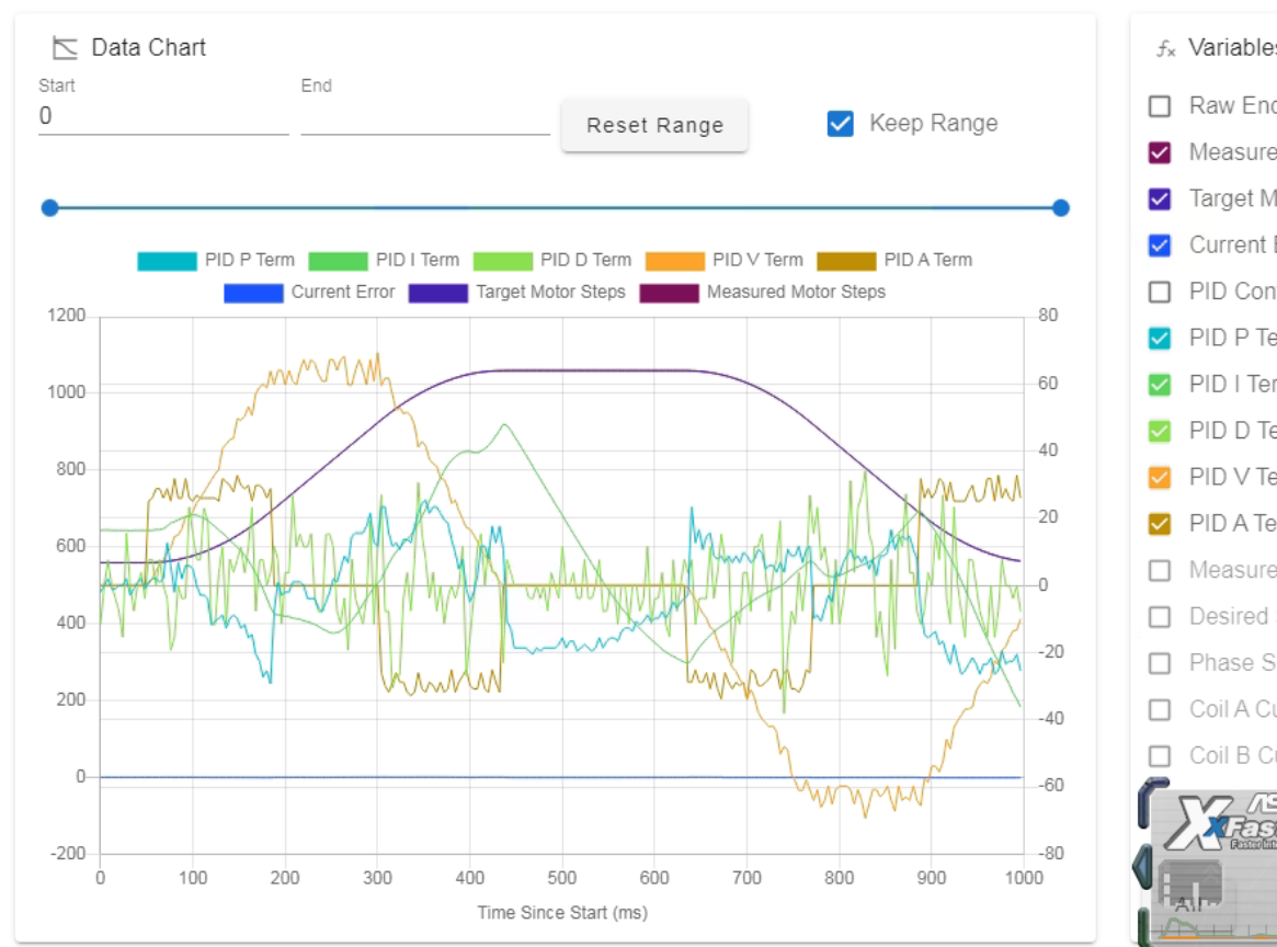
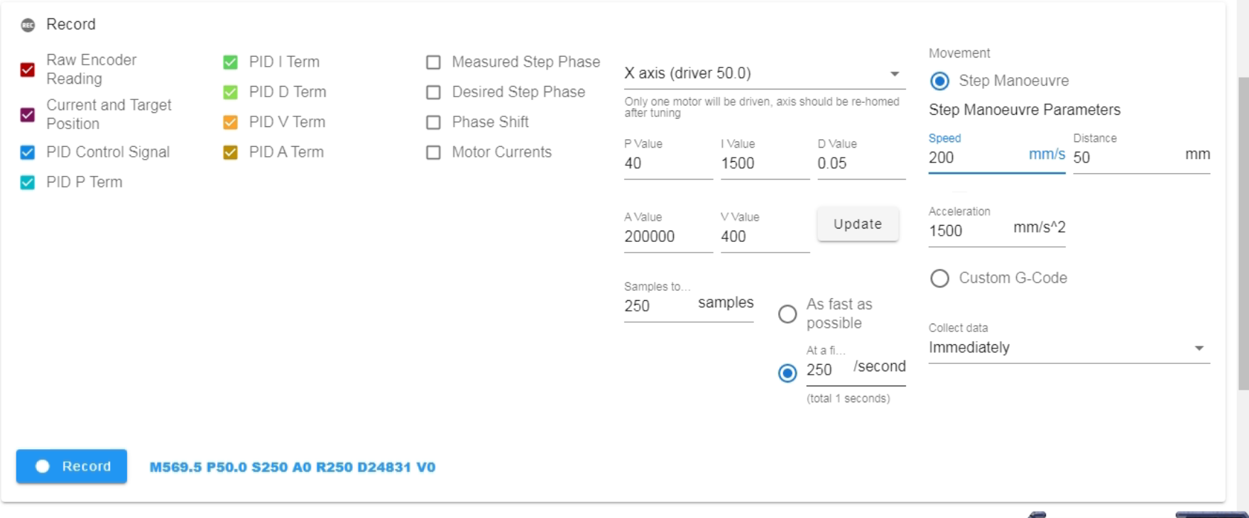
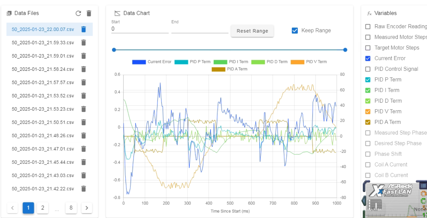
@dc42 does this manual tooling look OK?
This is what I cma up after following the tuning guide
-
RE: Plan to switch from normal steppers to 1HCL+ magnetic encodersposted in Using Duet Controllers
@dc42 Something to ask
When you do manual tuning with the plugin after it is finished.
How to save the tuned parameters?
Do I need to enter them in config.g in the 569.1 command? -
RE: Plan to switch from normal steppers to 1HCL+ magnetic encodersposted in Using Duet Controllers
@dc42 Thank you . I get this but these are on the machine. Any guidelines about PID tuning. I managed to make it today following the wiki guide and my graphs are more "noisy" is this to be expected. It is a big machine with 0.6 and 0.8revo nozzles. But I limit the acceleration a lot , hopin to improve this by going closed loop
-
RE: Plan to switch from normal steppers to 1HCL+ magnetic encodersposted in Using Duet Controllers
@dc42 Does that mean 0.9 steppers will have problems running in closed loop ?
-
RE: Plan to switch from normal steppers to 1HCL+ magnetic encodersposted in Using Duet Controllers
I think I found the culprit.
Originally due to heavy gantry my motors LDO-42STH60-MAC were runing at 1700 mA max current cutoff (2 Amps max)
I reduced the current to 1200 mA and now it is without vibrations in closed loop mode1/20/2025, 10:05:28 PM m569.6 p50.0 v3 Driver 50.0 calibration check succeeded, measured backlash is -0.067 step Residual encoder reading errors: min -5.0, max 11.3, rms 1.4 1/20/2025, 10:04:47 PM m569.6 p50.0 v2 Driver 50.0 calibration succeeded, measured backlash is -0.074 step Original encoder reading errors: min -13.8, max 14.1, rms 5.7 Corrections made: min -9.6, max 9.2, rms 5.6 1/20/2025, 10:04:11 PM m17 1/20/2025, 10:04:05 PM M906 X1200 Y1200 I0I still do not know if these numbers are good
-
RE: Plan to switch from normal steppers to 1HCL+ magnetic encodersposted in Using Duet Controllers
@jay_s_uk here is new calibration
and then the m122 p50.0
m122 b50 Diagnostics for board 50: Duet EXP1HCL rev 1.0a or earlier firmware version 3.6.0-beta.3 (2025-01-15 18:54:31) Bootloader ID: SAME5x bootloader version 2.4 (2021-12-10) All averaging filters OK Never used RAM 51588, free system stack 184 words Tasks: EncCal(1,nWait 6,0.3%,183) Move(3,nWait 7,0.0%,167) CLSend(3,nWait 6,0.0%,149) TMC(4,nWait 6,66.5%,317) HEAT(2,nWait 6,0.1%,105) CanAsync(5,nWait 4,0.0%,66) CanRecv(3,nWait 1,0.0%,65) CanClock(5,nWait 1,0.0%,64) MAIN(1,running,32.0%,253) IDLE(0,ready,0.0%,29) AIN(2,nWait 2,1.2%,255), total 100.0% Owned mutexes: Last reset 00:05:44 ago, cause: software Last software reset data not available Moves scheduled 0, hiccups 0 (0.00/0.00ms), segs 0, step errors 0 (types 0x0), maxLate 0 maxPrep 0, ebfmin 0.00 max 0.00 Phase step loop runtime (us): min=26, max=65, frequency (Hz): min=4807, max=18292 Peak sync jitter -7/7, peak Rx sync delay 190, resyncs 0/0, next timer interrupt due in 2 ticks, enabled, next step interrupt due in 4036578614 ticks, disabled VIN voltage: min 24.2, current 24.3, max 24.3 V12 voltage: min 12.0, current 12.0, max 12.1 MCU temperature: min 28.4C, current 29.1C, maDriver 0: pos 690, 320.0 steps/mm, position tolerance exceeded, failed to maintain position, SG min n/a, mspos 4, reads 25157, writes 8 timeouts 0 Last sensors broadcast 0x00000000 found 0 89 ticks ago, 0 ordering errs, loop time 0 CAN messages queued 2421, send timeouts 0, received 3688, lost 0, ignored 0, errs 0, boc 0, free buffers 38, min 38, error reg 0 dup 0, oos 0/0/0/0, bm 0, wbm 0, rxMotionDelay 0 Closed loop driver 0 mode: closed loop, pre-error threshold: 10.00, error threshold: 20.00, encoder type rotaryAS5047, position -1966 Encoder reverse polarity: no, full rotations -1, last angle 14418, minCorrection=-9.0, maxCorrection=9.2, agc 79, mag 4747, no error Tuning mode: 0, tuning error: 0, collecting data: no Accelerometer: none I2C bus errors 0, naks 0, contentions 0, other errors 0 -
RE: Plan to switch from normal steppers to 1HCL+ magnetic encodersposted in Using Duet Controllers
@jay_s_uk Reboot is fixed I uped the error in m596.1
It now just gives a warning when I send m17
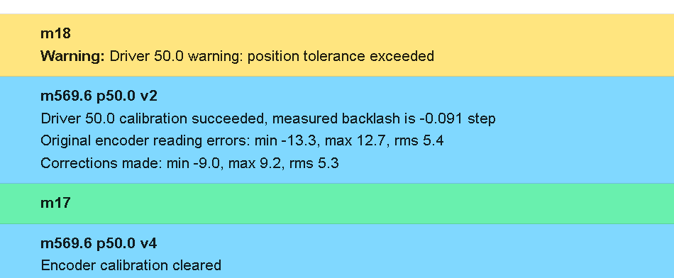
if I reset the tuning 569.6 p50.0 v4 it goes away
so the problem seems to be 0.9 steppers
it performs calibration and after that goes in resonance -
RE: Plan to switch from normal steppers to 1HCL+ magnetic encodersposted in Using Duet Controllers
I am stupid these are 0.9 mottors
tried to edit M569.1 with S400 parameter and the calibration went well , but after that the motor entered in such big resonance in stoped position , that crashed the whole board1/20/2025, 8:37:55 PM Connection established 1/20/2025, 8:37:25 PM Connection interrupted, attempting to reconnect... Network error: Request timed out 1/20/2025, 8:37:17 PM Warning: Driver 50.0 warning: position tolerance exceeded 1/20/2025, 8:37:16 PM m17 1/20/2025, 8:36:28 PM Warning: Driver 50.0 warning: position tolerance exceeded 1/20/2025, 8:36:27 PM Connection established 1/20/2025, 8:36:12 PM Connection interrupted, attempting to reconnect... Network error: Request timed out 1/20/2025, 8:36:03 PM m569.6 p50.0 v2 Driver 50.0 calibration succeeded, measured backlash is -0.084 step Original encoder reading errors: min -12.3, max 14.8, rms 5.2 Corrections made: min -9.0, max 10.0, rms 5.1 Warning: Driver 50.0 warning: position tolerance exceeded Warning: Driver 50.0 warning: position tolerance exceeded Warning: Driver 50.0 warning: position tolerance exceeded Warning: Driver 50.0 warning: position tolerance exceeded Warning: Driver 50.0 warning: position tolerance exceeded Warning: Driver 50.0 warning: position tolerance exceeded Warning: Driver 50.0 warning: position tolerance exceeded Warning: Driver 50.0 warning: position tolerance exceeded Warning: Driver 50.0 warning: position tolerance exceeded Warning: Driver 50.0 warning: position tolerance exceeded Warning: Driver 50.0 warning: position tolerance exceeded Warning: Driver 50.0 warning: position tolerance exceeded Warning: Driver 50.0 warning: position tolerance exceeded Warning: Driver 50.0 warning: position tolerance exceeded Warning: Driver 50.0 warning: position tolerance exceeded 1/20/2025, 8:35:37 PM m569.6 p50.0 Error: M569.6: Driver 50.0 calibration failed (no reason available) 1/20/2025, 8:35:14 PM m569.1 p50.0 Encoder type: rotaryAS5047 Magnetic encoder motor steps/rev 400, agc 80, mag 4715 PID parameters P=100.0 I=0.000 D=0.000 V=1000.0 A=0.0, torque constant 1.00Nm/A Warning/error threshold 1.00/2.00 1/20/2025, 8:35:03 PM m17 1/20/2025, 8:34:47 PM Upload of config.g successful after 0s 1/20/2025, 6:39:33 PM Connection established -
RE: Plan to switch from normal steppers to 1HCL+ magnetic encodersposted in Using Duet Controllers
Just in case downgraded back to 3.5.4 and the result is the same
-
RE: Plan to switch from normal steppers to 1HCL+ magnetic encodersposted in Using Duet Controllers
FAIL of the initial tuning
So after yestarday everythig was set in open loop and working , homing etc.
Today I remembered I have m3 treaded rods and managed to attach the first encoder
I unloaded the stepper ( removed the belt) and hit the wall
here is what I get1/20/2025, 5:05:29 PM M569.6 P50.0 V3 Error: M569.6: Driver 50.0 calibration failed (no reason available) 1/20/2025, 5:00:24 PM M569.6 P50.0 V2 Error: M569.6: Driver 50.0 calibration failed, the measured motion was less than expected, measured counts/step is about 41.0 Warning: Driver 50.0 warning: tuning/calibration failed 1/20/2025, 4:59:51 PM m17 1/20/2025, 4:59:29 PM M569.6 P50.0 V2 Error: M569.6: Driver is not enabled 1/20/2025, 4:59:05 PM Upload of config.g successful after 0sHere is my config.g
; Configuration file for Duet 3 (firmware version 3)
; executed by the firmware on start-up
;
; generated by RepRapFirmware Configuration Tool v3.2.3 on Thu May 27 2021 13:17:12 GMT+0300 (Eastern European Summer Time)

; General preferences
G90                                                    ; send absolute coordinates...
M83                                                    ; ...but relative extruder moves
M550 P"CoreXY500"                                     ; set printer name
M669 K1                                                ; select CoreXY mode

; Network
M552 P192.168.1.27 S1                                       ; enable network and acquire dynamic address via DHCP
M586 P0 S1                                             ; enable HTTP
M586 P1 S0                                             ; disable FTP
M586 P2 S0                                             ; disable Telnet
G4 S2   ;wait for expansion boards to start


; Drives
M569.1 P50.0 T3 E1:2 R100 I0 D0 ; Configure the Duet 3 Expansion 1HCL board at CAN address 50 with a Duet 3 magnetic encoder, warn if 1 fullstep threshold exceeded, error if 2 full steps threshold exceeded.
M569 P50.0 D4 S1 ;
;M569 P0.0 S1                                           ; physical drive 0.0 goes forwards
M569 P0.1 S0                                    ; physical drive 0.1 goes forwards
M569 P0.3 S0
M569 P0.4 S1
M569 P0.5 S1                                           ; physical drive 0.2 goes forwards
M569 P121.0 S1                                         ; physical drive 121.0 goes forwards
M584 X50.0 Y0.1 Z0.3:0.4:0.5 E121.0                             ; set drive mapping
M350 X16 Y16 Z16 E16 I1                                ; configure microstepping with interpolation
M92 X160.00 Y160.00 Z8280.00 E395.70                      ; set steps per mm
M350 X32 Y32 Z16 E16 I1
M566 X300.00 Y300.00 Z50.00 E120.00                    ; set maximum instantaneous speed changes (mm/min)
M203 X12000.00 Y12000.00 Z150.00 E1200.00                ; set maximum speeds (mm/min)
M201 X500.00 Y500.00 Z20.00 E500.00                    ; set accelerations (mm/s^2)
M906 X1700 Y1700 Z1000 E800 I30                           ; set motor currents (mA) and motor idle factor in per cent
M84 S30                                                ; Set idle timeout

; Axis Limits
M208 X-26 Y0 Z0 S1                                       ; set axis minima
M208 X500 Y330 Z365 S0                                 ; set axis maxima

; Endstops
M574 X1 S4                                             ; configure sensorless endstop for low end on X
M574 Y1 S4                                             ; configure sensorless endstop for low end on Y
M574 Z1 S2                                             ; configure Z-probe endstop for low end on Z
;M574 E1 S1
;Filament sensor BTT E1
M591 D0 P2 C"io8.in" S1 ;configure BTT smart filament sensor
; Z-Probe
M671 X-31.39:250:531.36 Y-18:433.3:-18 S10       ; Locations left, center, right
M558 P8 C"121.io2.in"  H3 F1000 T6000 A20 S0.005 ; PINDA set Z probe type to switch and the dive height + speeds
;M308 S2 P"121.temp1" A"PINDA" Y"thermistor" T100000 B3950
;M950 H2 C"out1" T2                                 ; create nozzle heater output on 121.out0 and map it to sensor 1
;M307 H2 B0 S1.00                                       ; disable bang-bang mode for heater  and set PWM limit
;M141 H2
;M143 H2 S90                                           ; set temperature limit for heater 1 to 280C
G31 P500 X30 Y0 Z1.48                            ; set Z probe trigger value, offset and trigger height
M557 X20:450 Y5:320 P5                             ; define mesh grid

; Heaters
M308 S0 P"temp0" Y"thermistor" T100000 B4138           ; configure sensor 0 as thermistor on pin temp0
M950 H0 C"out0" T0 Q10                                     ; create bed heater output on out0 and map it to sensor 0
M307 H0 B0 S1                                      ; disable bang-bang mode for the bed heater and set PWM limit
M140 H0                                                ; map heated bed to heater 0
M143 H0 S130                                          ; set temperature limit for heater 0 to 120C
M308 S1 P"121.temp0" Y"thermistor" T100000 B4725 C7.060000e-8       ; configure sensor 1 as thermistor on pin 121.temp0
M950 H1 C"121.out0" T1                                 ; create nozzle heater output on 121.out0 and map it to sensor 1
M307 H1 B0 S1.00                                       ; disable bang-bang mode for heater  and set PWM limit
M143 H1 S290     ; set temperature limit for heater 1 to 280C

M308 S2 A"Chamber" P"temp2" Y"thermistor" T100000 B4725 C7.06e-8
M950 H2 C"out2" T2                                 ; create nozzle heater output on 121.out0 and map it to sensor 1
M307 H2 R0.001 A11 C99999 D4000 B1   ; disable bang-bang mode for heater  and set PWM limit
M141 H2
M143 H2 S70

; Fans
M950 F0 C"121.out1"                               ; create fan 0 on pin 121.out1 and set its frequency
M106 P0 S0 B0.5 H-1                                         ; set fan 0 value. Thermostatic control is turned off
M950 F1 C"121.out2" Q500                               ; create fan 1 on pin 121.out2 and set its frequency
M106 P1 S1 H1 T45                                      ; set fan 1 value. Thermostatic control is turned on

; Tools
M563 P0 D0 H1 F0                                       ; define tool 0
G10 P0 X0 Y0 Z-0.15                                        ; set tool 0 axis offsets
G10 P0 R0 S0                                           ; set initial tool 0 active and standby temperatures to 0C

; Custom settings are not defined
M955 P121.0 I05 ;Accelerometer on Toolboard
; Miscellaneous
M575 P1 S1 B57600                                      ; enable support for PanelDue
M572 D0 S0.045 ; PA for ABS GD filament 0.4 nozzle
M501                                                   ; load saved parameters from non-volatile memory
M911 S22.5 R23.5 P"M913 X0 Y0 G91 M83 G1 Z3 E-5 F1000" ; set voltage thresholds and actions to run on power loss
and here are diagnostics right after the error
systemm122 === Diagnostics === RepRapFirmware for Duet 3 MB6HC version 3.6.0-beta.3 (2025-01-16 19:09:36) running on Duet 3 MB6HC v1.01 (standalone mode) Board ID: 08DJM-9P63L-DJMSS-6JKDA-3S86L-1BDB9 Used output buffers: 1 of 40 (21 max) === RTOS === Static ram: 136892 Dynamic ram: 127588 of which 16 recycled Never used RAM 79560, free system stack 200 words Tasks: NETWORK(1,ready,28.2%,175) ETHERNET(5,nWait 7,0.1%,316) HEAT(3,nWait 6,0.0%,347) Move(4,nWait 6,0.0%,333) TMC(4,nWait 6,3.1%,375) CanReceiv(6,nWait 1,0.0%,794) CanSender(5,nWait 7,0.0%,334) CanClock(7,delaying,0.0%,350) MAIN(1,running,68.5%,103) IDLE(0,ready,0.0%,29) USBD(3,blocked,0.0%,149), total 100.0% Owned mutexes: === Platform === Last reset 00:14:48 ago, cause: software Last software reset at 2025-01-20 16:59, reason: User, Gcodes spinning, available RAM 78828, slot 2 Software reset code 0x0003 HFSR 0x00000000 CFSR 0x00000000 ICSR 0x00400000 BFAR 0x00000000 SP 0x00000000 Task MAIN Freestk 0 n/a Error status: 0x00 Aux0 errors 0,0,0 MCU temperature: min 25.3, current 26.1, max 26.3 Supply voltage: min 24.1, current 24.1, max 24.2, under voltage events: 0, over voltage events: 0, power good: yes 12V rail voltage: min 12.1, current 12.1, max 12.2, under voltage events: 0 Heap OK, handles allocated/used 99/1, heap memory allocated/used/recyclable 2048/12/0, gc cycles 0 Events: 1 queued, 1 completed Date/time: 2025-01-20 17:13:57 Slowest loop: 3.22ms; fastest: 0.07ms USB interrupts 2 === Storage === Free file entries: 20 SD card 0 detected, interface speed: 25.0MBytes/sec SD card longest read time 1.0ms, write time 0.0ms, max retries 0 === Move === Segments created 0, maxWait 0ms, bed comp in use: none, height map offset 0.000, hiccups added 0/0 (0.00/0.00ms), max steps late 0, ebfmin 0.00, ebfmax 0.00 Pos req/act/dcf: 0.00/0/0.00 0.00/0/0.00 0.00/0/0.00 next step interrupt due in 9 ticks, disabled Driver 0: standstill, SG min n/a, mspos 8, reads 7783, writes 11 timeouts 0 Driver 1: standstill, SG min n/a, mspos 4, reads 7773, writes 21 timeouts 0 Driver 2: standstill, SG min n/a, mspos 8, reads 7783, writes 11 timeouts 0 Driver 3: standstill, SG min n/a, mspos 8, reads 7773, writes 21 timeouts 0 Driver 4: standstill, SG min n/a, mspos 8, reads 7773, writes 21 timeouts 0 Driver 5: standstill, SG min n/a, mspos 8, reads 7773, writes 21 timeouts 0 Phase step loop runtime (us): min=0, max=89, frequency (Hz): min=1666, max=2500 === DDARing 0 === Scheduled moves 0, completed 0, LaErrors 0, Underruns [0, 0, 0] Segments left 0, axes/extruders owned 0x00000000, drives owned 0x00000000 Code queue is empty === DDARing 1 === Scheduled moves 0, completed 0, LaErrors 0, Underruns [0, 0, 0] Segments left 0, axes/extruders owned 0x00000000, drives owned 0x00000000 Code queue is empty === Heat === Bed heaters 0 -1 -1 -1 -1 -1 -1 -1 -1 -1 -1 -1, chamber heaters 2 -1 -1 -1 -1 -1 -1 -1, ordering err=== GCodes === Movement locks held by null, null HTTP is idle in state(s) 0 Telnet is idle in state(s) 0 File is idle in state(s) 0 USB is idle in state(s) 0 Aux is idle in state(s) 0 Trigger is idle in state(s) 0 Queue is idle in state(s) 0 LCD is idle in state(s) 0 SBC is idle in state(s) 0 Daemon is idle in state(s) 0 Aux2 is idle in state(s) 0 Autopause is idle in state(s) 0 File2 is idle in state(s) 0 Queue2 is idle in state(s) 0 === Filament sensors === check 0 clear 6854308 Extruder 0 sensor: ok === CAN === Messages queued 7938, received 25025, lost 0, ignored 0, errs 0, boc 0 Longest wait 13ms for reply type 6018, peak Tx sync delay 376, free buffers 50 (min 49), ts 4213/4212/0 Tx timeouts 0,0,0,0,0,0 === Network === Slowest loop: 3.10ms; fastest: 0.03ms Responder states: MQTT(0) HTTP(0) HTTP(0) HTTP(0) HTTP(0) HTTP(0) HTTP(0) FTP(0) Telnet(0) Telnet(0) HTTP sessions: 2 of 8 = Ethernet = Interface state: active Error counts: 0 0 0 1 0 0 Socket states: 6 2 2 2 2 0 0 0 0 === Multicast handler === Responder is inactive, messages received 0, responses 0for the 1hcl board attached with the encoder
m122 b50
Diagnostics for board 50:
Duet EXP1HCL rev 1.0a or earlier firmware version 3.6.0-beta.3 (2025-01-15 18:54:31)
Bootloader ID: SAME5x bootloader version 2.4 (2021-12-10)
All averaging filters OK
Never used RAM 51588, free system stack 182 words
Tasks: EncCal(1,nWait 6,0.0%,312) Move(3,nWait 7,0.0%,167) CLSend(3,nWait 6,0.0%,149) TMC(4,nWait 6,60.5%,317) HEAT(2,nWait 6,0.0%,105) CanAsync(5,nWait 4,0.0%,66) CanRecv(3,nWait 1,0.0%,65) CanClock(5,nWait 1,0.0%,64) MAIN(1,running,38.4%,315) IDLE(0,ready,0.1%,29) AIN(2,nWait 2,1.0%,255), total 100.0%
Owned mutexes:
Last reset 00:15:41 ago, cause: software
Last software reset data not available
Moves scheduled 0, hiccups 0 (0.00/0.00ms), segs 0, step errors 0 (types 0x0), maxLate 0 maxPrep 0, ebfmin 0.00 max 0.00
Phase step loop runtime (us): min=26, max=65, frequency (Hz): min=8720, max=18292
Peak sync jitter -7/9, peak Rx sync delay 187, resyncs 0/0, next timer interrupt due in 11 ticks, enabled, next step interrupt due in 3589150588 ticks, disabled
VIN voltage: min 24.2, current 24.3, max 24.3
V12 voltage: min 12.0, current 12.0, max 12.1
MCU temperature: min 28.2C, current 29.1C, mDriver 0: pos -1080, 320.0 steps/mm, not tuned/calibrated, tuning/calibration failed, SG min n/a, mspos 4, reads 21334, writes 21 timeouts 0
Last sensors broadcast 0x00000000 found 0 181 ticks ago, 0 ordering errs, loop time 0
CAN messages queued 7704, send timeouts 0, received 12134, lost 0, ignored 0, errs 0, boc 0, free buffers 38, min 38, error reg 0
dup 0, oos 0/0/0/0, bm 0, wbm 0, rxMotionDelay 0
Closed loop driver 0 mode: closed loop, pre-error threshold: 1.00, error threshold: 2.00, encoder type rotaryAS5047, position 5520
Encoder reverse polarity: no, full rotations 0, last angle 5523, minCorrection=0.0, maxCorrection=0.0, agc 87, mag 4700, no error
Tuning mode: 0, tuning error: 0x6, collecting data: no
Accelerometer: none
I2C bus errors 12, naks 0, contentions 0, other errors 0
Any help is very much appreciated
-
RE: Plan to switch from normal steppers to 1HCL+ magnetic encodersposted in Using Duet Controllers
Happy to report in open loop it works as expected with the 2 HCL board
Homing works from the first try with 3.6 beta 3
Did not manage to test closed loop as my motors are 60 mm and the suitable screw is 80 mm M3 , that I did have only 1 pc left in the drawer. So tomorrow evening will be able to install encoders and test -
RE: Plan to switch from normal steppers to 1HCL+ magnetic encodersposted in Using Duet Controllers
@T3P3Tony Thank you
You are right about the timing. I am currently on 3.5.2 ( updated lastly because of the filament sensor on the main board feature when using tool board)
I will first try everything on 3.5.2 by manually setting the home position and will commission the setup. If everything plays as expected, we will go through switching to 3.6 beta 3
Your help here is one of the reasons duet ecosystem is my preferred for almost any project I do -
Plan to switch from normal steppers to 1HCL+ magnetic encodersposted in Using Duet Controllers
Hello,
I have been planning for more than a year to convert my big (600x400) ABS CoreXY printer to a closed loop.
For this more than an year ago I got 1HCL board+ duet magnetic encoders.
The machine is with Duet 3.
I spent today the time to read through the documentation and came up with the following plan, and please correct me where you think I made a wrong step or missed something- Based on the documentation, I will have to remove the steppers and install magnets and encoder boards on them. They have to be removed so I can perform the initial tuning of the encoder paired with the motor and magnet
- Install both HCL boards, connect them to the CAN in a daisy chain with the tool board I use, and connect motors and encoders also the power to both HCL boards
- Power them on by one and assign an address to each of them
- with everything wired, I have to perform tuning with M569.6
- To reinstall the steppers in the printer
- To perform PID tuning
I know it will take some questions additionally, but for now, I have one major question
In some older threads, I read that homing has to be performed in open-loop mode. Is that a fact?
Additionally, these axes (X and Y ) are using sensorless. homing Is this going to work in a closed loop?
In the past, I did set up a closed loop with duet two wifi, but it was with external drivers, and I just used an extension board to output direction, pthe ulse signal
Thank you for any advice and comments in advance