Duet3D Logo Duet3D
    • Tags
    • Documentation
    • Order
    • Register
    • Login
    1. Home
    2. martin7404
    3. Best
    • Profile
    • Following 3
    • Followers 1
    • Topics 26
    • Posts 300
    • Best 29
    • Controversial 0
    • Groups 0

    Best posts made by martin7404

    • Pinda2 to Duet3 toolboard

      EDIT: I1 and pullup removed from code
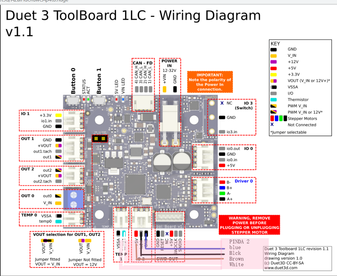
      I spent an hour or so reading the different posts to find how to wire and set Pinda2 probe on the tool board v1.1 of my new CoreXY machine. So here is some info for others to use. This will work for other inductive sensors, just do not connect temp1 connector
      Wiring
      Pinda_Duet_toolboard v1.1.png

      Configuration

      ; Z-Probe
      M671 X-31.39:250:531.36 Y18:433.3:18 S10       ; Locations left, center, right   
      M558 P8 C"121.io2.in"  H0.7 F1000 T6000 A20 S0.005 ; PINDA set Z probe type to switch and the dive height + speeds
      M308 S2 P"121.temp1" A"PINDA" Y"thermistor" T100000 B3950
      G31 P500 X-3.20 Y0 Z2.5                                    ; set Z probe trigger value, offset and trigger height
      M557 X20:485 Y41:360 P7                             ; define mesh grid
      

      Here is the probe repeatability test result

      6/6/2021, 9:26:30 AM	G32 bed probe heights: -0.001 -0.003 -0.003 -0.002 -0.002 -0.003 -0.002 -0.003 -0.002 -0.003 -0.001 -0.003 -0.003 -0.003 -0.002 -0.002 -0.001 -0.001 -0.002 -0.001 -0.000 -0.001 -0.002 -0.002 -0.002, mean -0.002, deviation from mean 0.001
      
      posted in Duet Hardware and wiring
      martin7404undefined
      martin7404
    • RE: Wrong Temp Monitored at Chamber Heater Fault

      @baua1024 With 3.4 I got this error only once for 48 hour printing already
      My chamber heater is this link text
      run trough SSR, I am using standard E3d V^ thermistor
      this is my config line

      M308 S2 A"Chamber" P"temp2" Y"thermistor" T100000 B4725 C7.06e-8
      M950 H2 C"out2" T2                                 ;
      M307 H2 A11 C99000 D2000 B1   ; 
      M141 H2
      M143 H2 S70
      
      posted in Duet Hardware and wiring
      martin7404undefined
      martin7404
    • RE: Duet 2 wifi Sapphire pro

      @mackiez Hi, Mine is highly modified with H2 extruder and 0.9 steppers on X and Y, so my curent config is not going to help . Here it is my config when I first set duet wifi on Sapphire pro. It is almost stock here , only Bltouch and E3d V6 block and heater with original heatsink and Chimera heatbreak

      ; General preferences
      G90                                     ; send absolute coordinates...
      M83                                     ; ...but relative extruder moves
      M550 P"TP BOX1.0a"                      ; set printer name
      M667 S1                                 ; select CoreXY mode
      ; Network
      M552 S1                                 ; enable network
      M586 P0 S1                              ; enable HTTP
      M586 P1 S0                              ; disable FTP
      M586 P2 S0                              ; disable Telnet
      ; Drives
      M569 P0 S0                              ; physical drive 0 goes forwards
      M569 P1 S0                              ; physical drive 1 goes forwards
      M569 P2 S0                              ; physical drive 2 goes backwards
      M569 P3 S0                             ; physical drive 3 goes forwards
      M584 X0 Y1 Z2 E3                        ; set drive mapping
      M350 X16 Y16 Z16 E16 I1                 ; configure microstepping with interpolation
      M92 X80.0 Y80.0 Z1600.00 E395.00      ; set steps per mm
      M566 X800.00 Y800.00 Z12.00 E300.00     ; set maximum instantaneous speed changes (mm/min)
      M203 X18000.00 Y18000.00 Z500.00 E6000.00 ; set maximum speeds (mm/min)
      M201 X2500.00 Y2500.00 Z100.00 E1500.00     ; set accelerations (mm/s^2)
      M906 X900 Y900 Z900 E1000 I30         ; set motor currents (mA) and motor idle factor in per cent
      M84 S30                                 ; Set idle timeout
      ; Axis Limits
      M208 X0 Y0 Z0 S1                        ; set axis minima
      M208 X210 Y210 Z200 S0                  ; set axis maxima
      ; Endstops
      M574 X1 Y2 Z1 S0                        ; set active low and disabled endstops
      ; Z-Probe
      M558 P5 H5 F120 T6000                   ; set Z probe type to switch and the dive height + speeds
      G31 P500 X0 Y0 Z2.5                     ; set Z probe trigger value, offset and trigger height
      M557 X15:215 Y15:195 S20                ; define mesh grid
      ; Heaters
      M307 H0 B0 S1.00                        ; disable bang-bang mode for the bed heater and set PWM limit
      M305 P0 T100000 B4138 R4700             ; set thermistor + ADC parameters for heater 0
      M143 H0 S120                            ; set temperature limit for heater 0 to 120C
      M305 P1 T100000 B4138 R4700             ; set thermistor + ADC parameters for heater 1
      M143 H1 S280                            ; set temperature limit for heater 1 to 280C
      ; Fans
      M106 P0 S0 I0 F500 H-1                  ; set fan 0 value, PWM signal inversion and frequency. Thermostatic control is turned off
      M106 P1 S1 I0 F500 H-1                ; set fan 1 value, PWM signal inversion and frequency. Thermostatic control is turned on
      ; Tools
      M563 P0 D0 H1 F0                        ; define tool 0
      G10 P0 X0 Y0 Z0                         ; set tool 0 axis offsets
      G10 P0 R0 S0                            ; set initial tool 0 active and standby temperatures to 0C
      ; Custom settings are not defined
      
      posted in Firmware installation
      martin7404undefined
      martin7404
    • RE: Dual Markforged :idle IDEX carriage is not still during print

      @sebkritikel https://www.youtube.com/watch?v=ImSpw3hpFJg

      posted in Tuning and tweaking
      martin7404undefined
      martin7404
    • RE: What firmware version are you using?

      Most probably it is some mistake in panel due manual operation, that made me change from - to + tool offset. It seems it is ok now

      posted in General Discussion
      martin7404undefined
      martin7404
    • RE: Toolboard v1.1 Accelerometer Orientation and Setup

      @frederik you may consider Pinda probe , it is 5 v

      posted in Duet Hardware and wiring
      martin7404undefined
      martin7404
    • RE: Md/Lg Format Printer Platform for Precision?

      I just finished building MULDEX 3d printer. It js a Rep Rap style project with 3 Z and 400x300 buildplate and kinematic coupling with . Corexyu kinematics, 2 independent dual extruders and duet wifi with duex and paneldue.

      posted in 3D Printing General Chat
      martin7404undefined
      martin7404
    • RE: Duet 2 wifi Sapphire pro

      @mackiez Could you photo your controller wiring and your end-stops on the frame

      posted in Firmware installation
      martin7404undefined
      martin7404
    • RE: Error: bad Command XXX W/RRF 3.2 and leveling issue

      yes
      first print finished with tool1 (left) 🙂
      here is my new config
      It is with PRF3.11 and I think It will work with PRF3.22 too

      G90                                             ; send absolute coordinates...
      M83                                             ; ...but relative extruder moves
      M550 P"Muldex"                                  ; set printer name
      
      
      ; Network
      M552 S1                                        ; enable network
      M586 P0 S1                                      ; enable HTTP
      M586 P1 S0                                      ; disable FTP
      M586 P2 S0                                      ; disable Telnet
      
      ; Drives
      M569 P0 S0                                      ; X physical drive 0 goes backwards
      M569 P1 S0                                      ; Y right physical drive 1 goes backwards
      M569 P2 S1                                      ; Y left physical drive 2 goes forwards
      M569 P3 S1                                      ; U physical drive 3 goes forwards
      M569 P4 S1                                     ; E1 physical drive 4 goes backwards
      M569 P5 S1                                      ; Z left physical drive 5 goes backwards
      M569 P6 S1                                     ; Z center physical drive 6 goes backwards
      M569 P7 S0                                      ; Z right physical drive 7 goes forwards
      M569 P8 S1                                      ; E2 physical drive 8 goes forwards
      
      M584 X0 Y1:2 U3 Z5:6:7 E4:8                     ; set drive mapping
      
      M350 X16 U16 Y16 Z16 E16:16 I1                                                           ; configure microstepping with interpolation
      M92 X199.7 U200 Y199.8:199.8 Z799.2:799.2:799.2 E813.07:830.00                        ; set steps per mm (1760nimble)
      M566 X1000.00 U1000.00 Y1000.00:1000.00 Z80.00:80.00:80.00 E100.00:100.00                ; set maximum instantaneous speed changes (mm/min)(Nimble 40)
      M203 X12000.00 U12000.00 Y12000.00:12000.00 Z1000.00:1000.00:1000.00 E4200.00:4200.00    ; set maximum speeds (mm/min)
      M201 X1310.00 U1310.00 Y1310.00:1310.00 Z35.00:35.00:35.00 E800.00:800.00                    ; set accelerations (mm/s^2)(500)(Nimble 120)
      M906 X900 U900 Y900:900 Z900:900:900 E1000:1000 I30                                        ; set motor currents (mA) and motor idle factor in per cent(Nimble 500)
      M84 S120                                                                                  ; Set idle timeout
      
      ; Axis Limits
      M208 X-18 Y0 U40 Z0 S1                          ; set axis min - adjust X to align nozzle
      M208 X350 U422.7 Y333 Z300 S0                   ; set axis max 
      
      M669 K0 Y1:-1:0:1				                ; select Markforged Kinematics Y to react with X and U
      
      ; Endstops
      M574 X1 S1 P"xstop"                             ;X axis active high endstop switch
      M574 Y2 S1 P"ystop+e1stop"                      ;Y Double max active high endstop switch
      ;M574 Y1 S4 ; configure sensorless endstop for low end on Y
      M574 U2 S1 P"e0stop"                            ;U axis active high endstop switch
      ;M574 Z2 S4
      
      ;Stall Detection(no used)
      ;M574 Y1 S4                                     ; Y axis stall detection
      ;M915 P1:9 S3 F1 R0                             ; Y axis stall detection
      
      ; Z-Probe
      M671 X-20.6:200:420.6 Y14.3:333.3:14.3 S10       ; Locations left, center, right          
      M950 S0 C"duex.e6heat"                          ; create servo pin 0 for BLTouch
      M558 P9 C"zprobe.in+zprobe.mod" H10 F600 A1 T12000   ; set Z probe type to bltouch and the dive height + speeds 
      G31 P25 X-29 Y0 Z3.97                           ; set Z probe trigger value, offset and trigger height(lower number farther away)1.8build 1.7glass 
      M557 X10:320 Y20:290 S60                       ; probe from X=10 to 390, Y=10 to 290mm with a mesh spacing of 20mm
      
      ; Heaters
      M308 S0 P"bedtemp" Y"thermistor" T100000 B4534 C9.565227e-8      ; configure sensor 0 as thermistor on pin bedtemp
      M950 H0 C"bedheat" T0                                            ; create bed heater output on bedheat and map it to sensor 0
      M143 H0 S120                                                     ; set temperature limit for heater 0 to 120C
      M307 H0 B0 S1.00                                                 ; disable bang-bang mode for the bed heater and set PWM limit
      M140 H0                                                          ; map heated bed to heater 0
      M308 S1 P"e0temp" Y"thermistor" T100000 B4725 C0 R4700  ; configure sensor 1 as thermistor on pin e0temp
      M950 H1 C"e0heat" T1                                             ; create nozzle heater output on e0heat and map it to sensor 1
      M143 H1 S280                                                     ; set temperature limit for heater 1 to 280C
      M307 H1 B0 S1.00                                                 ; disable bang-bang mode for heater  and set PWM limit
      M308 S2 P"e1temp" Y"thermistor" T100000 B4725 C0 R4700 ; configure sensor 2 as thermistor on pin e1temp
      M950 H2 C"e1heat" T2                                             ; create nozzle heater output on e1heat and map it to sensor 2
      M143 H2 S280                                                     ; set temperature limit for heater 2 to 280C
      M307 H2 B0 S1.00                                                 ; disable bang-bang mode for heater  and set PWM limit
      
      ; Fans
      M950 F0 C"fan0" Q500                             ; create fan 0 on pin fan0 and set its frequency
      M106 P0 S0 H-1                               ; set fan 0 value. Thermostatic control is turned off
      M950 F1 C"fan1" Q500                             ; create fan 1 on pin fan1 and set its frequency
      M106 P1 S1 H1 T45                                ; set fan 1 value. Thermostatic control is turned on
      M950 F2 C"fan2" Q500                             ; create fan 2 on pin fan2 and set its frequency
      M106 P2 S0 H-1                                   ; set fan 2 value. Thermostatic control is turned off
      M950 F3 C"duex.fan8" Q500                        ; create fan 3 on pin duex.fan8 and set its frequency
      M106 P3 S1 H2 T45                                ; set fan 3 value. Thermostatic control is turned on
      
      ; LEDs
      M950 F4 C"duex.fan6" ;Q500                       ; create LED 4 on pin duex.fan6 and set its frequency
      M106 P4 S128 H-1                                 ; set LED 4 value. Thermostatic control is turned OFF
      M950 F5 C"duex.fan7" ;Q500                       ; create LED 5 on pin duex.fan7 and set its frequency
      M106 P5 S128 H-1                                 ; set LED 5 value. Thermostatic control is turned OFF
      
      ; Tools
      M563 P0 D0 H1 F0 S"Left"                         ; define tool 0 Left 
      G10 P0 X0 Y0 Z-2.55                             ; set tool 0 axis offsets y was .45
      G10 P0 R0 S0                                     ; set initial tool 0 active and standby temperatures to 0C
      
      M563 P1 D1 H2 X3 F2 S"Right"                     ; define tool 1 Right
      G10 P1 X0 Y0 Z0                ; set tool 1 axis offsets - adjust Y to alignn nozzle
      G10 P1 R0 S0                                     ; set initial tool 1 active and standby temperatures to 0C
      
      ;M563 P2 D0:1 H1:2 X0:3 F0:2 S"Copy"              ; define tool 2 Copy
      ;G10 P2 X90 Y0 U-90 S0 R0                         ; set tool 2 axis offsets (WAS 105)
      ;M567 P2 E1:1         
      ;M568 P2 S1 ; turn on mixing for tool 2           ; set mix ratio 100% on both extruders
      ;G10 L1 P1 X0.0 Y0.0 Z-2.55
      
      M501                                             ; Record
      M593 F66.6
      T0 PO
      M575 P1 S1 B57600                                ;Panel due 
      ;G92 Z150
      ;G91
      ;G1 Z0.1 f100
      ;G90
      

      Untitled.png

      posted in General Discussion
      martin7404undefined
      martin7404
    • RE: Pinda2 to Duet3 toolboard

      TO warp up
      In the end I found that it is working both ways with or without pullup.
      I ended up changing pinda2 to superpinda, as far I got one delivered and super panda is working flawlessly with the same config

      posted in Duet Hardware and wiring
      martin7404undefined
      martin7404
    • RE: Bambu Lab Printer (for discussion, not promotion)

      I Got one .
      It is fast.
      Also very close to experince like geting HP laser jet and runing it. Espesialy with PLA.
      This thing will take away the good sleep of Prusa, ultimaker, Raise 3d etc

      posted in 3D Printing General Chat
      martin7404undefined
      martin7404
    • RE: Duet3 MD6HC fw update fubar?

      @jay_s_uk working OK now
      thank you

      posted in Firmware installation
      martin7404undefined
      martin7404
    • RE: Error: bad Command XXX W/RRF 3.2 and leveling issue

      copy mode working
      Untitled1.png

      posted in General Discussion
      martin7404undefined
      martin7404
    • RE: closed loop nema 17/23 driver/controller for Duet 3 6hc board

      @dc42 I am interested to test, willing to pay for the hardware

      posted in Duet Hardware and wiring
      martin7404undefined
      martin7404
    • RE: IDEX max 2000€

      @tecno link text

      posted in 3D Printing General Chat
      martin7404undefined
      martin7404
    • RE: Strange errors after update to 3.4

      @dc42 Thank you
      After careful review, the printed plate on which the tool board had a broken strain relief. During commissioning It was put as a test part, to be exchanged for ALu machined part, and left there for almost 6 months 🙂
      I will also re crimp the CAN cable at the tool board

      posted in Firmware installation
      martin7404undefined
      martin7404
    • RE: Independently leveled Z axis Issue

      I am not bragging, just chime in to share that with faulty board/drivers I got wrong compensation in triple Z setup, the rest is too much I agree.
      My bed is within a few thousands without the magnetic mat and the mat is off with 0.1 mm

      posted in General Discussion
      martin7404undefined
      martin7404
    • RE: Using externa switches(buttons) with duet 2

      @jay_s_uk Ok I think I got this
      Thank you very much
      I still do not get how to set it that
      when trigger (START is pressed) ON to strat the program with M23
      I have to make a macro of some sort I think?

      P.S I see now trigger#.g

      posted in Duet Hardware and wiring
      martin7404undefined
      martin7404
    • RE: Beta testers for multiple motion system support

      @wdenker i am in for this testing.
      I have a machne with 1 x axis and 2 independant Z axis with drilling velocity spindles VFD for simultaneously driling 2 diferent operations

      posted in Beta Firmware
      martin7404undefined
      martin7404
    • RE: Help with new custom printer - Prints have ringing around them

      @mrawesome987 well this type of linear guide uses C shaped bushings and as far the rods are mounted on Aluprofile that is not straight in terms of hundreds of millimeter , so they can go slightly out of alignment .

      posted in General Discussion
      martin7404undefined
      martin7404