Duet3D Logo Duet3D
    • Tags
    • Documentation
    • Order
    • Register
    • Login
    1. Home
    2. mrmkw
    • Profile
    • Following 0
    • Followers 0
    • Topics 1
    • Posts 5
    • Best 1
    • Controversial 0
    • Groups 0

    mrmkw

    @mrmkw

    1
    Reputation
    2
    Profile views
    5
    Posts
    0
    Followers
    0
    Following
    Joined Last Online

    mrmkw Unfollow Follow

    Best posts made by mrmkw

    • RE: Calibrating extrusion amounts

      Tried to run the attached macro as a job today. (Nonlinear_extrusion.gcode)

      Indeed, gcode command M221 does not work when used inside a macro. The figure and code below summarizes my findings and how I obtained them:

      9d767b68-cbf7-416a-80d8-9b5c49ae32ea-image.png

      Matlab commands to obtain parameters:

      x = [1 2 3 4 5 6] %different velocities in mm/s
      y_des = 50; %desired distance
      measured = [48.84 46.81 46.12 45.65 45.26 44.66]; %measured distance
      y1 = y_des./measured; %calculate the ratio
      p1 = polyfit(x,y1,2); %obtain second order polynomial approximation
      figure(1) %plot your results
      plot(x,y1)
      

      gcode to perform compensation

      M221 D0 S103.97                                                 ;fill in p1(3), see Matlab code
      M592 D0 A0.005 B0.0015 L0.45				;for A, fill in p1(2), for B, fill in p1(1)
      

      @Phaedrux, thanks for your help!

      posted in General Discussion
      mrmkwundefined
      mrmkw

    Latest posts made by mrmkw

    • RE: Calibrating extrusion amounts

      Tried to run the attached macro as a job today. (Nonlinear_extrusion.gcode)

      Indeed, gcode command M221 does not work when used inside a macro. The figure and code below summarizes my findings and how I obtained them:

      9d767b68-cbf7-416a-80d8-9b5c49ae32ea-image.png

      Matlab commands to obtain parameters:

      x = [1 2 3 4 5 6] %different velocities in mm/s
      y_des = 50; %desired distance
      measured = [48.84 46.81 46.12 45.65 45.26 44.66]; %measured distance
      y1 = y_des./measured; %calculate the ratio
      p1 = polyfit(x,y1,2); %obtain second order polynomial approximation
      figure(1) %plot your results
      plot(x,y1)
      

      gcode to perform compensation

      M221 D0 S103.97                                                 ;fill in p1(3), see Matlab code
      M592 D0 A0.005 B0.0015 L0.45				;for A, fill in p1(2), for B, fill in p1(1)
      

      @Phaedrux, thanks for your help!

      posted in General Discussion
      mrmkwundefined
      mrmkw
    • RE: Calibrating extrusion amounts

      I tried sending the command during printing a 2 wall think hollow rectangle.

      M221 D0 S200
      

      and the wall thickness indeed increases a bit, from 1.1mm to 1.5mm. If I put

      M221 D0 S10
      

      Hardly any plastic comes out. So this seems to work. Is there an easy way to test the behavior like I could with the macro that I have in the attachment?

      posted in General Discussion
      mrmkwundefined
      mrmkw
    • RE: Calibrating extrusion amounts

      @phaedrux, I was planning to include the construction with the if-statements in my print jobs, but for now I am just including

      M221 S102.71
      M592 D0 A0.0107 B0.00044 L0.45				;Nonlinear extrusion: Bx^2 + Ax + C
      

      In my macro to see if it works as expected. So for now, this is only tested in my macro.

      posted in General Discussion
      mrmkwundefined
      mrmkw
    • RE: Calibrating extrusion amounts

      @phaedrux Oops, all the ones were supposed to be a 2. Somehow missed that. I corrected that now.

      posted in General Discussion
      mrmkwundefined
      mrmkw
    • Calibrating extrusion amounts

      Dear all,

      I have been following this post to compensate for nonlinear extrusion. I slightly modified the file to see what happens if I introduce the adjusted extrusion parameters also and to give some extra info while doing the experiment:Nonlinear_extrusion.txt

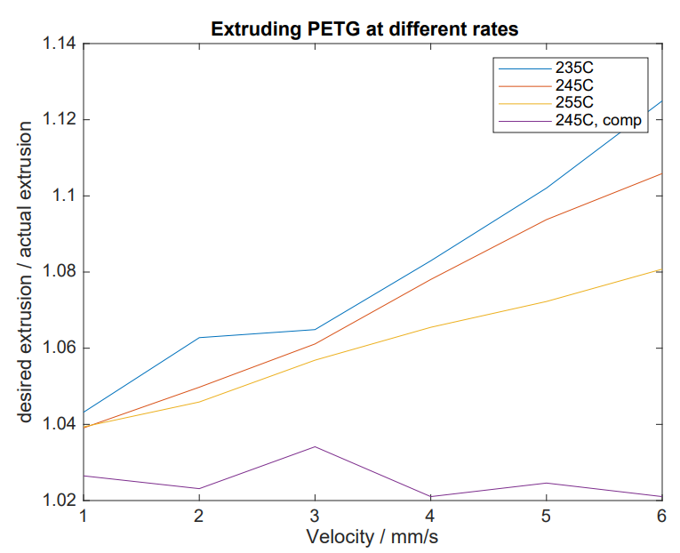
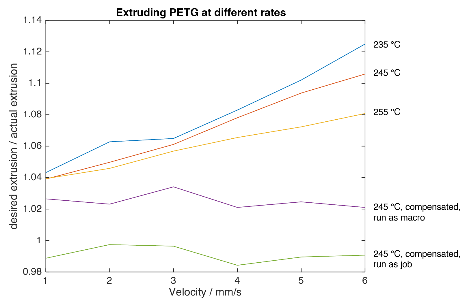
      I wanted to calibrate my PETG first. So I ran the macro 3 times each for temperatures of 235, 245 and 255 degrees Celsius. You can see the results in the figure. Then I made a second-order fit for each of the three lines so that each line would be approximated with Bx^2 + Ax + C. It was my understanding that I could use

      M592 D0 A0.0107 B0.00044 L0.45				;Nonlinear extrusion: Bx^2 + Ax + C
      

      To compensate for the Bx^2 and Ax. So I still needed to find a way to compensate for the C. As I already carefully calibrated my extruder steps per mm, and I could not find a gcode command for the extrusion multiplier, I decided to go for M221.
      I ended up with the following starting gcode to compensate for each temperature:

      {if temperature[0] < 240}
      M221 D0 S103.97
      M592 D0 A0.005 B0.0015 L0.45				;Nonlinear extrusion: Bx^2 + Ax + C 
      {endif}
      {if temperature[0] >= 240 and temperature[0] <= 250}
      M221 D0 S102.71
      M592 D0 A0.0107 B0.00044 L0.45				;Nonlinear extrusion: Bx^2 + Ax + C 
      {endif}
      {if temperature[0] > 250}
      M221 D0 S102.95
      M592 D0 A0.0093 B-0.00012 L0.45				;Nonlinear extrusion: Bx^2 + Ax + C 
      {endif}
      

      However, if I rerun my macro at 245 degrees Celsius with:

      M221 S102.71
      M592 D0 A0.0107 B0.00044 L0.45				;Nonlinear extrusion: Bx^2 + Ax + C
      

      I end up with the line labeled "245C, comp". It seems that the command M221 does not influence my result. I expected that if I insert e.g., M221 D0 S200, that if I command 50mm of extrusion, the printer would actually extrude 100 mm. Can somebody explain to me what I am doing wrong or if I am misunderstanding the way M221 works?

      1e171545-f029-4e03-938f-ea585bd0bc7c-image.png

      posted in General Discussion
      mrmkwundefined
      mrmkw