@apak Great that it worked out for you!
I Uploaded a Potential "Portable" Version for it,
(it is the Preparation Folder for the "Inno Setup Compiler", but can be used without installation...)
Basically with the Portable .ZIP Archive, Unzip it and if you let the Files stay together (in the Folder) and start the .exe, it should work as expected
https://drive.google.com/file/d/1h8VFJc-2HVDe2m1Smub98zgmQutajNtW/view?usp=drive_link
Posts made by NeueKlasse
-
RE: PanelDue Logo Firmware Compiler, Testers neededposted in Third-party software
-
RE: PanelDue Logo Firmware Compiler, Testers neededposted in Third-party software
@apak can you share these logos? as far as i learned during my experience with programming this software the .bmp file should be exactly 800x480 pixels and not greater than around 3mb...
-
PanelDue Logo Firmware Compiler, Testers neededposted in Third-party software
since i always want to see my Logo at Startup, i needed to compile each new
PanelDue Firmware to include a Logo, to ease up the process i created a
Tool to do everything on it's own.
The Old Standard Operation: https://www.instructables.com/How-to-Add-a-Splash-Screen-to-PanelDue/Now: I need You to test the Software extensively and give me Feedback what to change and what to improve on it!
Google Drive Link for Download .rar file
after Installation, make sure to run the Program as Administrator (Permission to Save your Work Paths via the Options Tab)Please left your thoughts

BR
Sebastian -
RE: Specialized Laser Communication Board (Duet 3 Family)posted in Duet Hardware and wiring
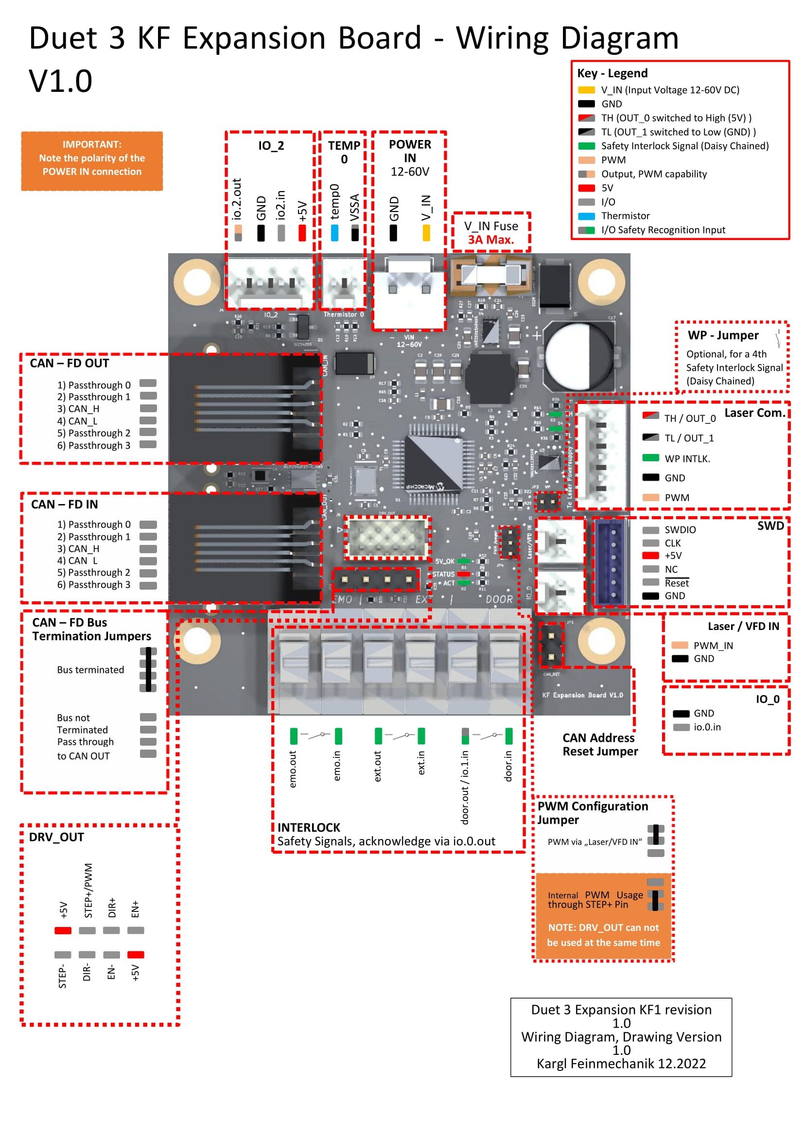
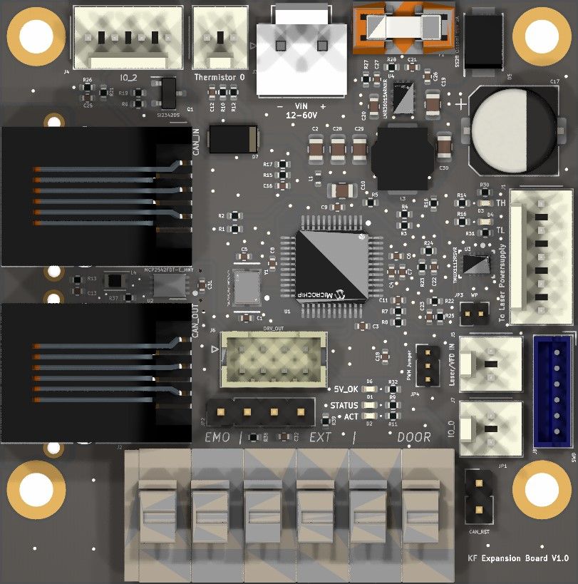
Attached Wiring Diagram

-
Specialized Laser Communication Board (Duet 3 Family)posted in Duet Hardware and wiring
Hi Guys, one Year passed by since i started to Create this Board.
It is based on the 1XD Expansion Board, (uses the Same Firmware)
it has the capability to use another CAN-FD Chip from TI on it's Backside
(TCAN1042 ) - (one or another)the Purpose from this Board is:
- direct Implementation from a Standard Laser Powersupply possible
- Door Closed Signal Recognition (Safety Reasons)
- Input for Watertemp, PWM Fan Regulation for a Watercooler.
- Safety for EMO, External Signal, DOOR via Spring Clamp Terminal.
the 1. Prototype is finished, Documentation is ongoing.
Open Things: the STEP+ Pin doesn't work as PWM source for the Laser at the Moment.
Software needs to be done, otherwise the possibility to Route a Wire from the Mainboard VFD Output to the VFD Input header on this Expansion board is there
Maybe DUET3D wants to add another Expansion Board to it's Portfolio.
otherwise it will be my own development Board to Simplify Wiring.A Happy New Year to you all!
Sebastian
-
Usable Laser / 5V PWM Outputs on Expansion Board 1XDposted in Laser Cutters
I want to know if it is Possible to use for example io2_out on the Expansion Board 1XD
together with M452Original Command:
M452 C"out9" R255 F200Modified Command:
(for CAN Address 40)M452 C"40.io2_out" R255 F200or is the Firmware not able to use it?
at the moment i cannot test it because i wait for the 1XD Board. -
RE: Using a Button with daemon.gposted in Gcode meta commands
Thanks, i don't had in mind that Duet has this Function, it works as expected!
I never read about Loops faster than 1 second in RRF, what is the maximum possible?
i suppose a while loop without a G4 Command inside can crash the Software?
it's also not easy to Edit the daemon.g file.. only after having the .part file that'll
be created after you try to edit the daemon.g file...
maybe it's possible to STOP the daemon.g file from Running to edit it? maybe with a M-Command?
for example the KUKA Roboters use a similar thing, called a "sps.sub" (submitinterpreter)
and it is possible to Stop it separately... -
Using a Button with daemon.gposted in Gcode meta commands
I want to use a Button to Switch an Output
(Button pressed (IO7.in) -> Output (Out7) on)
(Button released: Output off)I‘m not Sure if daemon.g is capable of.. let‘s say
a 100ms Cycletime (reliable), without bursting to
Much Energy of the Atmel Chip.
1 Second is way to slow for the goal to
switch a laser on/off,
And i hate to do that with the Touchscreen.. -
RE: Duet 3 MB6HC V1.01 I2C Connectionposted in Duet Hardware and wiring
@dc42 Is it possible to get a Schematic and Circuit drawings from the Board itself?
-
Duet 3 MB6HC V1.01 I2C Connectionposted in Duet Hardware and wiring
Is it possible to use the i2c protocol to communicate with the MB6HC Board?
(M260/261)
Which Connector to use? IO2 is documented with
„I2c possible with added Resistors“
But no further informationI want to connect a EEPROM to it.
-
3.4.0 b6 Issuesposted in Beta Firmware
I've encountered 2 Things after Installation (DWC and RRF)
(before i had beta 5 installed, without issue)=> The Status is always "Changing Tool", it doesn't Change the Status in DWC as well as on the PanelDue (7i) (Known Issue as far as the changelog says)
=> after Installation and a reboot nomore Macros are displayed on the PanelDue,
(in the Latest Release as well as in the Release before, so the PanelDue Firmware doesn't
create this issue)
The Macros are missing on the Status Page as well as in the Macros tab on PanelDue.
(before the Reboot they were Displayed)I encountered the Issues on 2 separate MB6HC Boards
-
RE: IO*.out Pin Assignment to gpOut with M950posted in Using Duet Controllers
yes i use that Parameter, in my case it's 255.
the R Parameter corresponds to Max Laser Power so in case it would be 100
on S100 the Laser Powersupply has a 100% ON PMW SignalA Max Value / Restriction Parameter would be good in M452!!!
I wanted to use a normal Slicer, in my Case Prusaslicer with a Normal Printerprofile.
the Only Thing that needs to be done is to wipe the Platform before every Layer,
to Add the Powder. and a Gcode Edit need to be done.
for example, to Convert "G1 X100 Y200 E0.055" into "G1 X100 Y200 E1 S100"It should be A Gcode with a E1 Signal to Enable the Laser and a S*** Signal to
set the Laserpower for each specific G1 move.i'm developing a special GCode Editor (Windows and Mac based) to set Laserpower for Raft, Supports, Infill, Shell's.
I Want to make it as easy as possible if the Printer is Ready for a potential Fan Out in the Future.and i don't want anyone to use a Overpriced Slicer for that purpose....
(for Printers without Galvo Head) -
RE: IO*.out Pin Assignment to gpOut with M950posted in Using Duet Controllers
@neueklasse I figured it out, the Invertation was a Problem... otherwise it works,
one Thing to point out: The M452 Command:M452 C"out9" R255 S0 F20000is it Possible to Change that Command so a "Max Value" can be Programmed?
For Example the X Command within M106 to set the Max Value that will be used.for The M571 Command.. When no Extruder or E Axis is defined in config.g
Does it still work? For Example G1 E100 F100 S100
(Move to X100 (and Control the specified output within M571) with 100mm/min and a Laser Power of 100/255 (40%) -
DWC Apply Settings Buttonposted in Duet Web Control
Where does the "Apply Settings" Button go that was mentioned in the Wiki?
https://duet3d.dozuki.com/Wiki/Duet_Web_Control_ManualHow to Store changed Items on the Duet Board without this Button?
-
RE: IO*.out Pin Assignment to gpOut with M950posted in Using Duet Controllers
@neueklasse
is it possible that out9 is always high PWM (5V)?
The other Fan PWM Outputs (Out4-6) are at 0V (no Duty Cycle) if the configured Fans are set to 0%.. -
RE: IO*.out Pin Assignment to gpOut with M950posted in Using Duet Controllers
@dc42
OK, thanks for the hint@cosmowave
i tried to invert it, nothing changes,
even after:M950 P5 C"io2.out" ; Assign Port 5 to io2.out (Laser ON/OFF) M42 P5 S0 M950 P6 C"io5.out" ; Assign Port 5 to io2.out (Laser ON/OFF) M42 P6 S0the Pins come on half a second after startup of the Board... this should be done with the 10K pulldownresistors.
another Problem i've encoutered:
M452 C"!out9" F20000        						 	 ; Enable Laser mode, on out9 and a PWM frequency of 20000Hz
M571 P"io5.out" S1								 		 ; set Output on while extruder is commanded, frequency and value
Afer the M452 Line the PWM Output is at 5V, shouldn't it be at 0V???
the Same with the M571 Line... io5.out is at 3.3V (ON) after it...If i delete the M452 and M571 Line and configure a Fan with M950 and M106 like:
M950 F4 C"!out9" Q20000						 		 ; Assign PWM Output out9 to Laser Power Supply on Port 4
M106 P4 C"Laserpower" S0 X150 H-1						 ; set Laser Power Supply name and maximum PWM value
The Duty Cycle is set to M106 S0... but the PWM Output (out9) is at 5V Constant... at it doesn't change...
-
IO*.out Pin Assignment to gpOut with M950posted in Using Duet Controllers
It would be interesting to know how that will be done Correctly,
after Startup of the Board (DUET3MB6HC 1.01)
the Pins are constanly at 3.3V (IO2.out and IO5.out<=>GND).afterwards when i assign Port 5 and 6 to these Pins using M950
the Output pins are still at 3.3Vif i set M42 P5, P6 S0 then the Pins turn off (0V)....
is that behavior normal, or do i need to turn off the pin with M42 after Assignment w. M950 in
the config.g file?i don't want these Pins to come on until i want it...
-
Homing Issue 3.4.0-b3posted in Using Duet Controllers
RRF + DWC Version 3.4.0-b3
;G28, homeall.g
T0
G91                     ; relative positioning
G1 H1 X999 Y999 F2000   ; move quickly to X and Y axis endstops and stop there (first pass)
G1 H0 X-5 Y-5 F12000    ; go back a few mm
G1 H1 X5 Y5 F200        ; move slowly to X and Y axis endstops once more (second pass)
G1 H0 X-5 Y-5 F500      ; move back to free up the endstop
G90                     ; absolute positioning
the Problem is that (with the homeall.g file, or G28) the Y Axis moves till the endstop then
(simultaneously) the X Axis homes normally (to the endstop, back and a second time...)
but the Y Axis doesn't want to move after it's first pass (macro line 4)....(as a result the Homing failed) UNTIL i home it explicitly alone (with the homey.g macro), sometimes it homes 2 times (X or Y Axis) which i don't understand?!?!?!but the Problem i described above only occurs for the Y Axis (until now)
it seems that this problem occurs when the 2 Axis Homed simultaniously.
i can't Say when this issue started exactly, but it was working a while ago... (and it works without
problems on the Chiron the same way), the only difference is that here it's Core XYWhen i Change the Macro this way:
;G28, homeall.g
T0
G91                     ; relative positioning
G1 H1 X999 F2000        ; move quickly to X axis endstop and stop there (first pass)
G1 H1 Y999 F2000        ; move quickly to Y axis endstop and stop there (first pass)
G1 H0 X-5 Y-5 F12000    ; go back a few mm
G1 H1 X5 F200           ; move slowly to X axis endstop once more (second pass)
G1 H1 Y5 F200           ; move slowly to Y axis endstop once more (second pass)
G1 H0 X-5 Y-5 F500      ; move back to free up the endstop
G90                     ; absolute positioning
it works without problems..
in case of the homing that occurs 2 times after one tap on the homing button.....maybe the possibility of an Paneldue Homing Button issue??
PanelDue-3.4.0-pre2