you were too fast and replied before I removed my post!
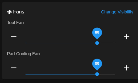
I assumed the 'tool fan' was the hotend fan, but it isn't. If I take both of these down to 0, only the part cooling fan stops.
Although I'm not sure why there are two fans showing in the UI
you were too fast and replied before I removed my post!
I assumed the 'tool fan' was the hotend fan, but it isn't. If I take both of these down to 0, only the part cooling fan stops.
Although I'm not sure why there are two fans showing in the UI
deleted.
Thought it wasn't working but it is
Well I thought it was working, but I think there is still a slight issue with the duet config or slicer.
The hotend fan turns on correctly at 45C
But the part cooling fan doesn't start automatically. If I use the fan slider once the print has started it does work.
The slicer is set to enable it at layer two.
thanks for you r help with this. I removed the 1LC, reflowed the connectors with plenty of flux and cleaned with IPA - now working.
Yes definitely bridged to 3.3v (top two pins on the IO1 connector)
Here you go
; Configuration file for Duet WiFi (firmware version 3)
; executed by the firmware on start-up
;
; generated by RepRapFirmware Configuration Tool v3.2.3 on Wed Jun 02 2021 18:38:31 GMT+0800 (中国标准时间)

; General preferences

G90                                              ; send absolute coordinates...
M83                                              ; ...but relative extruder moves
M550 P"BLV mgn Cube"                		     ; set printer name
M669 K1                                          ; select CoreXY mode

; Network
M552 S1                                          ; enable network
M586 P0 S1                                       ; enable HTTP
M586 P1 S0                                       ; disable FTP
M586 P2 S0                                       ; disable Telnet

G4 S1   										 ;wait for expansion boards to start

; Drives
M569 P0.0 S0 D2                                  ; X motor runs forwards
M569 P0.1 S1 D2                                  ; Y motor runs forwards
M569 P0.2 S1 D2                                  ; physical drive 0.2 goes backwards
M569 P0.3 S1 D2                                  ; physical drive 0.2 goes backwards
M569 P0.4 S1 D2                                  ; physical drive 0.2 goes backwards
M569 P121.0 S1 D2                                ; physical drive 121.0 goes backwards
M584 X0.0 Y0.1 Z0.2:0.3:0.4 E121.0               ; set drive mapping
M350 X16 Y16 Z16 E16 I1                          ; configure microstepping with interpolation
M92 X200.00 Y200.00 Z3200.00 E700                ; set steps per mm
M671 X0:290:290 Y155:62:255 S3 		 		     ; leadscrews at rear left, front middle and rear right
M566 X600.00 Y600.00 Z150.00 E3000.00            ; set maximum instantaneous speed changes (mm/min) - increased Z and E
M203 X20000.00 Y20000.00 Z2000.00 E6000.00       ; set maximum speeds (mm/min) - increased E
M201 X3000.00 Y3000.00 Z200.00 E5000.00          ; set accelerations (mm/s^2)
M906 X1600 Y1600 Z1000 E800 I30                  ; set motor currents (mA) and motor idle factor in per cent
M84 S30                                          ; Set idle timeout

; Axis Limits
M208 X-3:305 Y-50:305 Z-1.0:500.0

; Endstops
M574 X1 S1 P"121.io1.in"                         ; configure active-high endstop for low end on X via pin io1.in
M574 Y2 S1 P"io6.in"                             ; configure active-high endstop for HIGH end on Y via pin io6.in
M564 H1											 ; allow jog without homing

; Z-Probe
M950 S0 C"^121.io0.out"                          ; create servo pin 0 for BLTouch
M558 P9 C"^121.io0.in" H3 F120 T10000            ; set Z probe type to bltouch and the dive height + speeds
G31 P500 X0 Y66 Z2.55                            ; set Z probe trigger value, offset and trigger height. + brings noxzzle closer to bed
M557 X5:305 Y20:290 P8                       	 ; define mesh grid

; Heaters
M308 S0 P"temp0" Y"thermistor" T100000 B3950     ; configure sensor 0 as thermistor on pin temp0
M950 H0 C"out0" T0                               ; create bed heater output on out0 and map it to sensor 0
M307 H0 R0.291 C1127.4 D26.90 S1.00				 ; Set PID for bed values
M140 H0                                          ; map heated bed to heater 0
M143 H0 S100                                     ; set temperature limit for heater 0 to 100C

M308 S1 P"121.temp0" Y"thermistor" T100000 B4725 C7.06e-8 	; configure sensor 1 as thermistor on pin 121.temp0 //0 to 1
M950 H1 C"121.out0" T1                           			; create nozzle heater output on 121.out0 and map it to sensor 1
M307 H1 B0 R3.089 C258.2:154.4 D5.95 S1.00 V23.7 			; Set PID for hotend values
M143 H1 S280                                     			; set temperature limit for heater 1 to 280C

; Fans
M950 F0 C"121.out2" Q80                          ; create hotend fan 0 on pin toolboard out1 and set its frequency
M106 P0 S0 H1 T45 C"Hotend Fan"                  ; set fan 0 value. Thermostatic control is turned on
M950 F1 C"121.out1" Q250                         ; create cooling fan 1 on pin toolboard out1 and set its frequency
M106 P1 S0 H-1 B1 C"Part Cooling Fan"            ; set fan 1 value. Thermostatic control is turned off

; Tools
M563 P0 D0 H1 F1   					 			 ; define tool 0
G10 P0 X0 Y0 Z0 								 ; set tool 0 axis offsets
G10 P0 R0 S0 									 ; set initial tool 0 active and standby temperatures to 0C
;
;M563 P1 D0 H1 F1 						  		 ; define tool 1
;G10 P1 X0 Y0 Z0 								 ; set tool 1 axis offsets
;G10 P1 R0 S0 									 ; set initial tool 1 active and standby temperatures to 0C

; Custom settings
M564 H0                                   	   	 ; Let the Jog buttons work blv: added to allow jog buttons
M575 P1 B57600 S1								 ; Connection to  PanelDue
;955 P121.0 I10									 ; Accelerometer

; Pressure advance
;M572 D0 S0.04

; Miscellaneous
M911 S21 R22 P"M913 X0 Y0 G91 M83 G1 Z3 E-5 F1000" ; set voltage thresholds and actions to run on power loss
@gloomyandy It does! But the hotend temp drops to -271 and the thermostatic fan comes on.
testing the endstop with a multimeter shows its closed when not pressed and open when pressed.
I've temporarily disconnected it and bridged IO1.in and GND with a screwdriver - no change on the X endstop.
thanks I found it. I can see the Y tool position change to green on activation.
For some reason X still doesn't work 
Just double checking I'm correct to have it wired to IO1.in and GND? not IO1.in and 3.3v?
thanks, looks like we're on the same page. I just updated.
No errors anymore, but the X endstop still isn't detected by the endstop monitor..
I've just forced a firmware update with M997 B121
Now i dont get an error and it will attempt to home. But crashed into the endstop as it doesn't seem to be detecting it.
endstop plugin also isn't detecting when pressed.

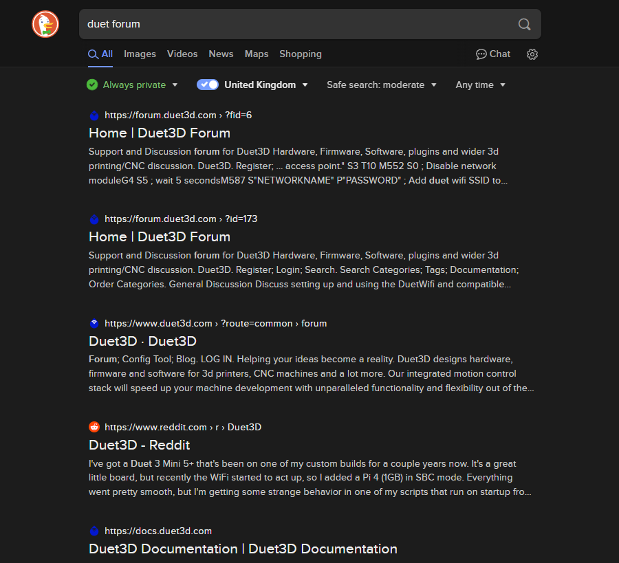
quite a difference when searching for something specific on the forum

I've just replaced my toolboard as it developed a fault.
Everything is working except my X endstop.
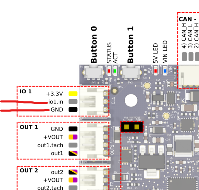
I have it wired to IO1.in and GND.
The endstop opens when pressed (tested working)
this is my config.
; Endstops
M574 X1 S1 P"121.io1.in"
M574 Y2 S1 P"io6.in"
M564 H1

; Z-Probe
M950 S0 C"^121.io0.out"                          ; create servo pin 0 for BLTouch
M558 P9 C"^121.io0.in" H3 F120 T10000            ; set Z probe type to bltouch and the dive height + speeds
G31 P500 X0 Y66 Z2.55                            ; set Z probe trigger value, offset and trigger height. + brings noxzzle closer to bed
M557 X5:305 Y20:290 P8                       	 ; define mesh grid
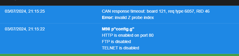
When homing X I get
	G28 X
Error: in file macro line 7: G1: Failed to enable endstops
; homex.g
; called to home the X axis
;
; generated by RepRapFirmware Configuration Tool v3.2.3 on Thu Jul 01 2021 15:51:11 GMT+0100 (British Summer Time)
G91               ; relative positioning
G1 H2 Z5 F6000    ; lift Z relative to current position
G1 H1 X-330 F1800 ; move quickly to X axis endstop and stop there (first pass)
G1 X5 F6000       ; go back a few mm
G1 H1 X-330 F360  ; move slowly to X axis endstop once more (second pass)
G1 H2 Z-5 F6000   ; lower Z again
G90               ; absolute positioning
Noting in the code has changed relating to the end stop so it must be a hardware or wiring issue?
I've installed the endstop plugin and X is not triggered and doesn't trigger when I manually press the endstop
This probably isn't the correct place for this, but I dont think there is a discussion that fits.
I've noticed that this forum is no longer returned in Google search results. Also, searching "Duet forum" doesn't bring up a direct link
I'm not quite sure what the problem is..
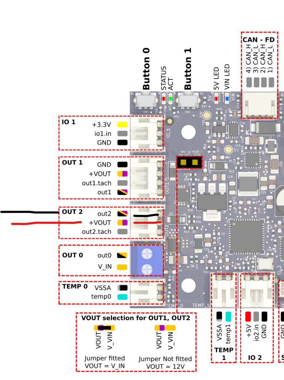
I have it wired like this on out2
; Configuration file for Duet WiFi (firmware version 3)
; executed by the firmware on start-up
;
; generated by RepRapFirmware Configuration Tool v3.2.3 on Wed Jun 02 2021 18:38:31 GMT+0800 (中国标准时间)

; General preferences

G90                                              ; send absolute coordinates...
M83                                              ; ...but relative extruder moves
M550 P"BLV mgn Cube"                		     ; set printer name
M669 K1                                          ; select CoreXY mode

; Network
M552 S1                                          ; enable network
M586 P0 S1                                       ; enable HTTP
M586 P1 S0                                       ; disable FTP
M586 P2 S0                                       ; disable Telnet

G4 S1   										 ;wait for expansion boards to start

; Drives
M569 P0.0 S0 D2                                  ; X motor runs forwards
M569 P0.1 S1 D2                                  ; Y motor runs forwards
M569 P0.2 S1 D2                                  ; physical drive 0.2 goes backwards
M569 P0.3 S1 D2                                  ; physical drive 0.2 goes backwards
M569 P0.4 S1 D2                                  ; physical drive 0.2 goes backwards
M569 P121.0 S1 D2                                ; physical drive 121.0 goes backwards
M584 X0.0 Y0.1 Z0.2:0.3:0.4 E121.0               ; set drive mapping
M350 X16 Y16 Z16 E16 I1                          ; configure microstepping with interpolation
M92 X200.00 Y200.00 Z3200.00 E700                ; set steps per mm
M671 X0:290:290 Y155:62:255 S3 		 		     ; leadscrews at rear left, front middle and rear right
M566 X600.00 Y600.00 Z150.00 E3000.00            ; set maximum instantaneous speed changes (mm/min) - increased Z and E
M203 X20000.00 Y20000.00 Z2000.00 E6000.00       ; set maximum speeds (mm/min) - increased E
M201 X3000.00 Y3000.00 Z200.00 E5000.00          ; set accelerations (mm/s^2)
M906 X1600 Y1600 Z1000 E800 I30                  ; set motor currents (mA) and motor idle factor in per cent
M84 S30                                          ; Set idle timeout

; Axis Limits
M208 X-3:305 Y-50:305 Z-1.0:500.0
; Endstops
M574 X1 S1 P"121.io1.in"                         ; configure active-high endstop for low end on X via pin io0.in !!!!!!!change!!!!!! 0 to 1
M574 Y2 S1 P"io6.in"                             ; configure active-high endstop for HIGH end on Y via pin io6.in
M564 H1											 ; allow jog without homing

; Z-Probe
M950 S0 C"^121.io0.out"                          ; create servo pin 0 for BLTouch
M558 P9 C"^121.io0.in" H3 F120 T10000            ; set Z probe type to bltouch and the dive height + speeds
G31 P500 X0 Y66 Z2.55                            ; set Z probe trigger value, offset and trigger height. + brings noxzzle closer to bed
M557 X5:305 Y20:290 P8                       	 ; define mesh grid

; Heaters
M308 S0 P"temp0" Y"thermistor" T100000 B3950     ; configure sensor 0 as thermistor on pin temp0
M950 H0 C"out0" T0                               ; create bed heater output on out0 and map it to sensor 0
M307 H0 R0.291 C1127.4 D26.90 S1.00				 ; Set PID for bed values
M140 H0                                          ; map heated bed to heater 0
M143 H0 S100                                     ; set temperature limit for heater 0 to 100C

M308 S1 P"121.temp0" Y"thermistor" T100000 B4725 C7.06e-8 	; configure sensor 1 as thermistor on pin 121.temp0 //0 to 1
M950 H1 C"121.out0" T1                           			; create nozzle heater output on 121.out0 and map it to sensor 1
M307 H1 B0 R3.089 C258.2:154.4 D5.95 S1.00 V23.7 			; Set PID for hotend values
M143 H1 S280                                     			; set temperature limit for heater 1 to 280C

; Fans
M950 F0 C"121.out1" Q80                         ;create hotend fan 0 on pin toolboard out1 and set its frequency
M106 P0 S0 H1 T45 C"Hotend Fan"                 ;set fan 0 value. Thermostatic control is turned on
M950 F1 C"121.out2" Q250                         ; create cooling fan 1 on pin toolboard out2 and set its frequency
M106 P1 S0 H-1 B1 C"Part Cooling Fan"            ; set fan 1 value. Thermostatic control is turned off

; Tools
M563 P0 D0 H1 F1   					 			 ; define tool 0
G10 P0 X0 Y0 Z0 								 ; set tool 0 axis offsets
G10 P0 R0 S0 									 ; set initial tool 0 active and standby temperatures to 0C
;
;M563 P1 D0 H1 F1 						  		 ; define tool 1
;G10 P1 X0 Y0 Z0 								 ; set tool 1 axis offsets
;G10 P1 R0 S0 									 ; set initial tool 1 active and standby temperatures to 0C

; Custom settings
M564 H0                                   	   	 ; Let the Jog buttons work blv: added to allow jog buttons
M575 P1 B57600 S1								 ; Connection to  PanelDue
M955 P121.0 I10									 ; Accelerometer

; Pressure advance
;M572 D0 S0.04

; Miscellaneous
M911 S21 R22 P"M913 X0 Y0 G91 M83 G1 Z3 E-5 F1000" ; set voltage thresholds and actions to run on power loss
@dc42 I wonder if that pin became dry when it overheated, as I have had it installed for at least two years without issue.
I hadn't realised it wasn't manufactured by you guys. I might wire the fan back to the mainboard for now while I order and wait for a genuine board to arrive.
@dc42 Thanks. I've pulled off the 1LC to clean with IPA. I think I've spotted the problem.
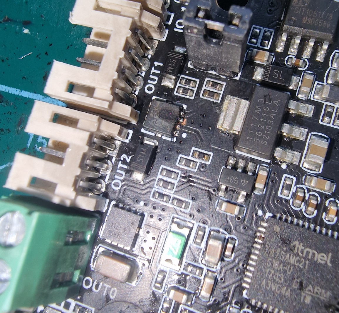
It looks like something has caused the IC controlling Out 1 to blow.
I can move the part cooling fan down to Out2 to reatin PWM but it sounds like there isn't anywhere else on the 1LC for the extruder fan?
As far as I can see, my options are to connect it to VIN (it will obviously always be running).
Wire it back to the main board
Replace the 1LC.
Can you suggest anything else I've missed?
I've installed a new part cooling fan, and the problem persists. I think the issue is with 'Out1'.
this is my current setup;
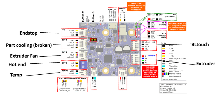
Would it be possible to move the hotend/extruder fan to IO2?
thi swould free up out2 (which seems to have speed control) for me to connect the part cooling fan?