• Tags
  • Documentation
  • Order
  • Register
  • Login
Duet3D Logo Duet3D
  • Tags
  • Documentation
  • Order
  • Register
  • Login
  1. Home
  2. Ray11
  • Profile
  • Following 0
  • Followers 0
  • Topics 19
  • Posts 49
  • Best 0
  • Controversial 0
  • Groups 0

Ray11

@Ray11

0
Reputation
2
Profile views
49
Posts
0
Followers
0
Following
Joined 2 Apr 2020, 05:20 Last Online 10 May 2022, 01:33

Ray11 Unfollow Follow

Latest posts made by Ray11

  • Louder noise/resonance on U axis

    I am having this issue on my IDEX printer where the u-axis for the second extruder is significantly louder compared to the x-axis. There seemed to be more vibrations when moving causing the extruder to resonance with it
    I tried a couple of things but it doesn't seem to improve the situation:

    • switching the driver of U axis
    • switching the stepper motor
    • enabling/disabling interpolation
    • change to 256 microstep

    Here is my config.g, I made sure the configuration for both x and u axis are the same (except for 256 microstep on u axis currently):

    ; Configuration file for Duet 3 (firmware version 3)
    ; executed by the firmware on start-up
    ;
    ; generated by RepRapFirmware Configuration Tool v2.1.8 on Wed Apr 01 2020 22:14:44 GMT-0500 (Central Daylight Time)
    
    ; General preferences
    G90                                             ; send absolute coordinates...
    M83                                             ; ...but relative extruder moves
    M550 P"IDEX"                            ; set printer name
    M575 P1 B57600 S1
    
    ; Network
    M552 P0.0.0.0 S1                                ; enable network and acquire dynamic address via DHCP
    M586 P0 S1                                      ; enable HTTP
    M586 P1 S0                                      ; disable FTP
    M586 P2 S0                                      ; disable Telnet
    
    ; Drives
    M569 P0.0 S1 D3                                  ; physical drive 0.0 goes forwards
    M569 P0.1 S0 D3                                   ; physical drive 0.0 goes forwards
    M569 P0.2 S1 D3                                   ; physical drive 0.2 goes forwards
    M569 P0.3 S1 D0                                ; physical drive 0.3 goes forwards
    M569 P0.4 S1 D3                                   ; physical drive 0.4 goes forwards
    M569 P0.5 S1 D3                                   ; physical drive 0.5 goes forwards
    M584 X0.0 U0.3 Y0.1 Z0.2 E0.4:0.5                    ; set drive mapping
    M350 X16 U256 Y16 Z16 E16:16 I1                      ; configure microstepping with interpolation
    M92 X160.00 U2560.00 Y80.00 Z400.00 E932.00:932.00      ; set steps per mm
    M566 X900.00 U900.00 Y900.00 Z12.00 E120.00:120.00      ; set maximum instantaneous speed changes (mm/min)
    M203 X12000.00 U12000.00 Y9000.00 Z1500.00 E6000.00:6000.00 ; set maximum speeds (mm/min)
    M201 X1500.00 U1500.00 Y1500.00 Z1000.00 E250.00:250.00      ; set accelerations (mm/s^2)
    M906 X700 U700 Y800 Z600 E1000:1000 I30                ; set motor currents (mA) and motor idle factor in per cent
    M84 S30                                         ; Set idle timeout
    
    ; Axis Limits
    M208 X-46 U0 Y0 Z0 S1                                ; set axis minima
    M208 X270 U314 Y205 Z200.6 S0                          ; set axis maxima
    
    ; Endstops
    M574 X1 P"io1.in" S1                                      ; configure sensorless endstop for low end on X
    M574 U2 P"io2.in" S1
    M574 Y2 P"!io5.in" S1                                      ; configure sensorless endstop for low end on Y
    M574 Z2 P"io6.in" S1                                      ; configure sensorless endstop for low end on Z
    M915 P0:1 S10 R1
    M915 P2 S10 R1
    
    ; Z-Probe
    M558 P1 I0 C"io3.in" A5 R0.4 H3 F1200 T9000                 ; set Z probe type to switch and the dive height + speeds
    G31 P220 X0 Y0 Z-100                            ; set Z probe trigger value, offset and trigger height
    
    ; Heaters
    M308 S0 P"temp0" Y"thermistor" T100000 B4138    ; configure sensor 0 as thermistor on pin temp0
    M950 H0 C"out0" T0                              ; create bed heater output on out0 and map it to sensor 0
    M143 H0 S80                                    ; set temperature limit for heater 0 to 120C
    M307 H0 B0 S0.8                               ; enable bang-bang mode for the bed heater and set PWM limit
    M307 H0 A84.5 C473.8 D1.4
    M140 H0                                         ; map heated bed to heater 0
    M308 S1 P"temp1" Y"thermistor" T100000 B4138    ; configure sensor 1 as thermistor on pin temp1
    M950 H1 C"out1" T1                              ; create nozzle heater output on out1 and map it to sensor 1
    M143 H1 S270                                    ; set temperature limit for heater 1 to 240C
    M307 H1 B0 S0.6                                ; disable bang-bang mode for heater  and set PWM limit
    M307 H1 A593.7 C179.8 D9.3 V24.0
    M308 S2 P"temp2" Y"thermistor" T100000 B4138    ; configure sensor 2 as thermistor on pin temp2
    M950 H2 C"out2" T2                              ; create nozzle heater output on out2 and map it to sensor 2
    M143 H2 S270                                    ; set temperature limit for heater 2 to 240C
    M307 H2 B0 S0.6                                ; disable bang-bang mode for heater  and set PWM limit
    M307 H2 A532.1 C165.0 D10.3 V24.0
    M572 D0:1 S0.1:0.1								;Pressure Advance
    M570 H1 P10 T20
    M570 H2 P10 T20


    ; Fans
    M950 F0 C"out7" Q500                            ; create fan 0 on pin out4 and set its frequency
    M106 P0 L1.0 S0 H1 T60 S1.00                               ; set fan 0 value. Thermostatic control is turned on
    M950 F1 C"out8" Q500                            ; create fan 1 on pin out5 and set its frequency
    M106 P1 S0 H-1                                  ; set fan 1 value. Thermostatic control is turned off
    M950 F2 C"out4" Q500                            ; create fan 2 on pin out7 and set its frequency
    M106 P2 L1.0 S0 H2 T60 S1.0                               ; set fan 2 value. Thermostatic control is turned on
    M950 F3 C"out9" Q500                            ; create fan 3 on pin out6 and set its frequency
    M106 P3 S0 H-1                                  ; set fan 3 value. Thermostatic control is turned off
    
    M950 F5 C"out5" Q500
    M106 P5 S0 H-1
    
    ; Tools
    M563 P0 D0 H1 F0:1                              ; define tool 0
    G10 P0 X0 Y0 Z0                                 ; set tool 0 axis offsets
    G10 P0 R0 S0                                    ; set initial tool 0 active and standby temperatures to 0C
    M563 P1 D1 H2 X3 F0:3                              ; define tool 1
    G10 P1 U0.0 Y0.0 Z-0.4                                 ; set tool 1 axis offsets
    G10 P1 R0 S0                                    ; set initial tool 1 active and standby temperatures to 0C
    
    ; Custom settings are not defined
    T0
    M150 X0 
    
    posted in Using Duet Controllers
    undefined
    Ray11
    23 Nov 2021, 19:49
  • RE: IDEX z probing question

    @o_lampe Do you know if there is an example code I can look up to adjust the leadscrew? It would be really nice to store the offset, do some math, and then print it out as a prompt on the LCD display.
    I think if I wire all endstops with series and connect them to active high, then once one is triggered, the entire circuit will switch to low. I can then use only one io port on duet.

    posted in Duet Hardware and wiring
    undefined
    Ray11
    23 Nov 2021, 15:58
  • RE: IDEX z probing question

    @t3p3tony So I think the correct way to frame this question is if I can use G30 to probe 4 points, record the "G32 bed probe heights" and save it to heightmap.csv using gcodes defined in the firmware?

    posted in Duet Hardware and wiring
    undefined
    Ray11
    22 Nov 2021, 19:25
  • RE: IDEX z probing question

    @t3p3tony Your point is right, what I thought about this is that I will first level the bed manually, then probe the four microswitches, record the offset at each probing point, and update the offset of each. I just wonder if currently, RepRap firmware allows individual offset and mixed tools for probing. Sorry, it is quite a wired use case.

    posted in Duet Hardware and wiring
    undefined
    Ray11
    22 Nov 2021, 18:49
  • RE: IDEX z probing question

    @t3p3tony https://youtu.be/EDbU1zlC3Ss?t=148
    So instead of mounting microswitches on the hotend, which is pretty crammed for an idex setup. I want to try to mount the microswitches on the bed instead.

    posted in Duet Hardware and wiring
    undefined
    Ray11
    22 Nov 2021, 18:20
  • IDEX z probing question

    I previously saw someone/company using endstop mounted on the carriage to probe the bed with 4 points (I will add the link to video if I can find it). Two on the left using left extruder, two on the right using right extruder. I would like to try mounting 4 limit switches on the bed wiring them in series such that I can use the left extruder to touch the left two and vise versa. This means that there will be some z offset for each of the limit switches and I need to probe the mesh with two extruders. I searched around and couldn't find any resources on that. I'm thinking of something like this:

    T0
    G30 P0 X20 Y50 Z-99999 H3.5 
    G30 P1 X20 Y200 Z-99999 H3.1
    T1
    G30 P2 X210 Y200 Z-99999 H3.2
    G30 P3 X210 Y50 Z-99999 H3.1 S4


    But G30 with S parameter seemed only to be for printers with multiple z motors.

    Thanks!

    posted in Duet Hardware and wiring
    undefined
    Ray11
    22 Nov 2021, 18:13
  • RE: Printing Metal with FDM?

    @theruttmeister Learned a lot. Thank you so much for this comprehensive answer!

    posted in 3D Printing General Chat
    undefined
    Ray11
    6 Oct 2020, 19:51
  • Printing Metal with FDM?

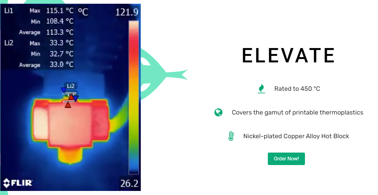
    Currently, processes from desktop metal and markforge require buying a sintering oven to do that. Able to directly print metal on an FDM printer will definitely be awesome and game-changing. Slice engineering's copperhead hotend can go up to 450 C and some welding filaments for aluminum melts at 600 - 650 C. I wonder in theory if there is a hotend that can reach that temperature, will it be possible to directly melt and print metal welding filaments that way? I guess the finished part doesn't need to compete with machining and casting strength but still could be way better than most plastics.
    e975db62-f813-49c7-9ea0-39e2e87700c9-image.png

    posted in 3D Printing General Chat
    undefined
    Ray11
    6 Oct 2020, 18:54
  • Extrude until user click something

    Hi all. I am trying to implement something resembling the Ultimaker filament switching routine on RRF3. Ultimaker allows the machine to extrude material until the user clicks a button to stop the extrusion. I wonder if it is possible to achieve this with either a while loop + M291 or use an M291 command to terminate a, for example, G1 E99999 command?

    posted in Duet Hardware and wiring
    undefined
    Ray11
    17 Aug 2020, 03:16
  • Question related to multiple Z endstop setup

    I have a z_max endstop that is using a switch and a z_min endstop with a probe. Normally, I would use the z_max endstop for homing the printer. I am wondering if I first use the z_max endstop and home the printer, and then use G30 with the probe, what is the current z_axis referencing with? Is it the probe or the previous z_max endstop?

    posted in Duet Hardware and wiring
    undefined
    Ray11
    14 Jun 2020, 16:58
Unless otherwise noted, all forum content is licensed under CC-BY-SA