Duet3D Logo Duet3D
    • Tags
    • Documentation
    • Order
    • Register
    • Login
    1. Home
    2. Ray11
    3. Posts
    • Profile
    • Following 0
    • Followers 0
    • Topics 19
    • Posts 49
    • Best 0
    • Controversial 0
    • Groups 0

    Posts made by Ray11

    • Louder noise/resonance on U axis

      I am having this issue on my IDEX printer where the u-axis for the second extruder is significantly louder compared to the x-axis. There seemed to be more vibrations when moving causing the extruder to resonance with it
      I tried a couple of things but it doesn't seem to improve the situation:

      • switching the driver of U axis
      • switching the stepper motor
      • enabling/disabling interpolation
      • change to 256 microstep

      Here is my config.g, I made sure the configuration for both x and u axis are the same (except for 256 microstep on u axis currently):

      ; Configuration file for Duet 3 (firmware version 3)
      ; executed by the firmware on start-up
      ;
      ; generated by RepRapFirmware Configuration Tool v2.1.8 on Wed Apr 01 2020 22:14:44 GMT-0500 (Central Daylight Time)
      
      ; General preferences
      G90                                             ; send absolute coordinates...
      M83                                             ; ...but relative extruder moves
      M550 P"IDEX"                            ; set printer name
      M575 P1 B57600 S1
      
      ; Network
      M552 P0.0.0.0 S1                                ; enable network and acquire dynamic address via DHCP
      M586 P0 S1                                      ; enable HTTP
      M586 P1 S0                                      ; disable FTP
      M586 P2 S0                                      ; disable Telnet
      
      ; Drives
      M569 P0.0 S1 D3                                  ; physical drive 0.0 goes forwards
      M569 P0.1 S0 D3                                   ; physical drive 0.0 goes forwards
      M569 P0.2 S1 D3                                   ; physical drive 0.2 goes forwards
      M569 P0.3 S1 D0                                ; physical drive 0.3 goes forwards
      M569 P0.4 S1 D3                                   ; physical drive 0.4 goes forwards
      M569 P0.5 S1 D3                                   ; physical drive 0.5 goes forwards
      M584 X0.0 U0.3 Y0.1 Z0.2 E0.4:0.5                    ; set drive mapping
      M350 X16 U256 Y16 Z16 E16:16 I1                      ; configure microstepping with interpolation
      M92 X160.00 U2560.00 Y80.00 Z400.00 E932.00:932.00      ; set steps per mm
      M566 X900.00 U900.00 Y900.00 Z12.00 E120.00:120.00      ; set maximum instantaneous speed changes (mm/min)
      M203 X12000.00 U12000.00 Y9000.00 Z1500.00 E6000.00:6000.00 ; set maximum speeds (mm/min)
      M201 X1500.00 U1500.00 Y1500.00 Z1000.00 E250.00:250.00      ; set accelerations (mm/s^2)
      M906 X700 U700 Y800 Z600 E1000:1000 I30                ; set motor currents (mA) and motor idle factor in per cent
      M84 S30                                         ; Set idle timeout
      
      ; Axis Limits
      M208 X-46 U0 Y0 Z0 S1                                ; set axis minima
      M208 X270 U314 Y205 Z200.6 S0                          ; set axis maxima
      
      ; Endstops
      M574 X1 P"io1.in" S1                                      ; configure sensorless endstop for low end on X
      M574 U2 P"io2.in" S1
      M574 Y2 P"!io5.in" S1                                      ; configure sensorless endstop for low end on Y
      M574 Z2 P"io6.in" S1                                      ; configure sensorless endstop for low end on Z
      M915 P0:1 S10 R1
      M915 P2 S10 R1
      
      ; Z-Probe
      M558 P1 I0 C"io3.in" A5 R0.4 H3 F1200 T9000                 ; set Z probe type to switch and the dive height + speeds
      G31 P220 X0 Y0 Z-100                            ; set Z probe trigger value, offset and trigger height
      
      ; Heaters
      M308 S0 P"temp0" Y"thermistor" T100000 B4138    ; configure sensor 0 as thermistor on pin temp0
      M950 H0 C"out0" T0                              ; create bed heater output on out0 and map it to sensor 0
      M143 H0 S80                                    ; set temperature limit for heater 0 to 120C
      M307 H0 B0 S0.8                               ; enable bang-bang mode for the bed heater and set PWM limit
      M307 H0 A84.5 C473.8 D1.4
      M140 H0                                         ; map heated bed to heater 0
      M308 S1 P"temp1" Y"thermistor" T100000 B4138    ; configure sensor 1 as thermistor on pin temp1
      M950 H1 C"out1" T1                              ; create nozzle heater output on out1 and map it to sensor 1
      M143 H1 S270                                    ; set temperature limit for heater 1 to 240C
      M307 H1 B0 S0.6                                ; disable bang-bang mode for heater  and set PWM limit
      M307 H1 A593.7 C179.8 D9.3 V24.0
      M308 S2 P"temp2" Y"thermistor" T100000 B4138    ; configure sensor 2 as thermistor on pin temp2
      M950 H2 C"out2" T2                              ; create nozzle heater output on out2 and map it to sensor 2
      M143 H2 S270                                    ; set temperature limit for heater 2 to 240C
      M307 H2 B0 S0.6                                ; disable bang-bang mode for heater  and set PWM limit
      M307 H2 A532.1 C165.0 D10.3 V24.0
      M572 D0:1 S0.1:0.1								;Pressure Advance
      M570 H1 P10 T20
      M570 H2 P10 T20


      ; Fans
      M950 F0 C"out7" Q500                            ; create fan 0 on pin out4 and set its frequency
      M106 P0 L1.0 S0 H1 T60 S1.00                               ; set fan 0 value. Thermostatic control is turned on
      M950 F1 C"out8" Q500                            ; create fan 1 on pin out5 and set its frequency
      M106 P1 S0 H-1                                  ; set fan 1 value. Thermostatic control is turned off
      M950 F2 C"out4" Q500                            ; create fan 2 on pin out7 and set its frequency
      M106 P2 L1.0 S0 H2 T60 S1.0                               ; set fan 2 value. Thermostatic control is turned on
      M950 F3 C"out9" Q500                            ; create fan 3 on pin out6 and set its frequency
      M106 P3 S0 H-1                                  ; set fan 3 value. Thermostatic control is turned off
      
      M950 F5 C"out5" Q500
      M106 P5 S0 H-1
      
      ; Tools
      M563 P0 D0 H1 F0:1                              ; define tool 0
      G10 P0 X0 Y0 Z0                                 ; set tool 0 axis offsets
      G10 P0 R0 S0                                    ; set initial tool 0 active and standby temperatures to 0C
      M563 P1 D1 H2 X3 F0:3                              ; define tool 1
      G10 P1 U0.0 Y0.0 Z-0.4                                 ; set tool 1 axis offsets
      G10 P1 R0 S0                                    ; set initial tool 1 active and standby temperatures to 0C
      
      ; Custom settings are not defined
      T0
      M150 X0 
      
      posted in Using Duet Controllers
      Ray11undefined
      Ray11
    • RE: IDEX z probing question

      @o_lampe Do you know if there is an example code I can look up to adjust the leadscrew? It would be really nice to store the offset, do some math, and then print it out as a prompt on the LCD display.
      I think if I wire all endstops with series and connect them to active high, then once one is triggered, the entire circuit will switch to low. I can then use only one io port on duet.

      posted in Duet Hardware and wiring
      Ray11undefined
      Ray11
    • RE: IDEX z probing question

      @t3p3tony So I think the correct way to frame this question is if I can use G30 to probe 4 points, record the "G32 bed probe heights" and save it to heightmap.csv using gcodes defined in the firmware?

      posted in Duet Hardware and wiring
      Ray11undefined
      Ray11
    • RE: IDEX z probing question

      @t3p3tony Your point is right, what I thought about this is that I will first level the bed manually, then probe the four microswitches, record the offset at each probing point, and update the offset of each. I just wonder if currently, RepRap firmware allows individual offset and mixed tools for probing. Sorry, it is quite a wired use case.

      posted in Duet Hardware and wiring
      Ray11undefined
      Ray11
    • RE: IDEX z probing question

      @t3p3tony https://youtu.be/EDbU1zlC3Ss?t=148
      So instead of mounting microswitches on the hotend, which is pretty crammed for an idex setup. I want to try to mount the microswitches on the bed instead.

      posted in Duet Hardware and wiring
      Ray11undefined
      Ray11
    • IDEX z probing question

      I previously saw someone/company using endstop mounted on the carriage to probe the bed with 4 points (I will add the link to video if I can find it). Two on the left using left extruder, two on the right using right extruder. I would like to try mounting 4 limit switches on the bed wiring them in series such that I can use the left extruder to touch the left two and vise versa. This means that there will be some z offset for each of the limit switches and I need to probe the mesh with two extruders. I searched around and couldn't find any resources on that. I'm thinking of something like this:

      T0
      G30 P0 X20 Y50 Z-99999 H3.5 
      G30 P1 X20 Y200 Z-99999 H3.1
      T1
      G30 P2 X210 Y200 Z-99999 H3.2
      G30 P3 X210 Y50 Z-99999 H3.1 S4


      But G30 with S parameter seemed only to be for printers with multiple z motors.

      Thanks!

      posted in Duet Hardware and wiring
      Ray11undefined
      Ray11
    • RE: Printing Metal with FDM?

      @theruttmeister Learned a lot. Thank you so much for this comprehensive answer!

      posted in 3D Printing General Chat
      Ray11undefined
      Ray11
    • Printing Metal with FDM?

      Currently, processes from desktop metal and markforge require buying a sintering oven to do that. Able to directly print metal on an FDM printer will definitely be awesome and game-changing. Slice engineering's copperhead hotend can go up to 450 C and some welding filaments for aluminum melts at 600 - 650 C. I wonder in theory if there is a hotend that can reach that temperature, will it be possible to directly melt and print metal welding filaments that way? I guess the finished part doesn't need to compete with machining and casting strength but still could be way better than most plastics.
      e975db62-f813-49c7-9ea0-39e2e87700c9-image.png

      posted in 3D Printing General Chat
      Ray11undefined
      Ray11
    • Extrude until user click something

      Hi all. I am trying to implement something resembling the Ultimaker filament switching routine on RRF3. Ultimaker allows the machine to extrude material until the user clicks a button to stop the extrusion. I wonder if it is possible to achieve this with either a while loop + M291 or use an M291 command to terminate a, for example, G1 E99999 command?

      posted in Duet Hardware and wiring
      Ray11undefined
      Ray11
    • Question related to multiple Z endstop setup

      I have a z_max endstop that is using a switch and a z_min endstop with a probe. Normally, I would use the z_max endstop for homing the printer. I am wondering if I first use the z_max endstop and home the printer, and then use G30 with the probe, what is the current z_axis referencing with? Is it the probe or the previous z_max endstop?

      posted in Duet Hardware and wiring
      Ray11undefined
      Ray11
    • RE: IDEX Homing Issues

      Hi, I later found out that it was in my config.g file while I configured the end-stop setting wrong. The U axis endstop is set to minimum where in reality it should be homing to the maximum. Thanks for the follow-up.

      posted in Duet Hardware and wiring
      Ray11undefined
      Ray11
    • RE: DWC Loading Issue

      @Phaedrux
      DWC version: 2.1.5
      RRF version: 3.0.1 RC-11

      posted in Duet Web Control
      Ray11undefined
      Ray11
    • RE: DWC Loading Issue

      It seemed happen when I use the "printername".local address. The GUI loads fine with the IP address.
      Here is my config.g

      ; Configuration file for Duet 3 (firmware version 3)
      ; executed by the firmware on start-up
      ;
      ; generated by RepRapFirmware Configuration Tool v2.1.8 on Wed Apr 01 2020 22:14:44 GMT-0500 (Central Daylight Time)
      
      ; General preferences
      G90                                             ; send absolute coordinates...
      M83                                             ; ...but relative extruder moves
      M550 P"IDEX"                            ; set printer name
      M575 P1 B57600 S1
      
      ; Network
      M552 P0.0.0.0 S1                                ; enable network and acquire dynamic address via DHCP
      M586 P0 S1                                      ; enable HTTP
      M586 P1 S0                                      ; disable FTP
      M586 P2 S0                                      ; disable Telnet
      
      ; Drives
      M569 P0.0 S1 D3                                  ; physical drive 0.0 goes forwards
      M569 P0.1 S1 D3                                   ; physical drive 0.0 goes forwards
      M569 P0.2 S0 D3                                   ; physical drive 0.2 goes forwards
      M569 P0.3 S1 D3                                   ; physical drive 0.3 goes forwards
      M569 P0.4 S0 D3                                   ; physical drive 0.4 goes forwards
      M569 P0.5 S0 D3                                   ; physical drive 0.5 goes forwards
      M584 X0.0 U0.1 Y0.2 Z0.3 E0.4:0.5                    ; set drive mapping
      M350 X16 U16 Y16 Z16 E16:16 I1                      ; configure microstepping with interpolation
      M92 X200.00 U200.00 Y80.00 Z400.00 E420.00:420.00      ; set steps per mm
      M566 X900.00 U900.00 Y900.00 Z12.00 E120.00:120.00      ; set maximum instantaneous speed changes (mm/min)
      M203 X9000.00 U9000.00 Y6000.00 Z1500.00 E1200.00:1200.00 ; set maximum speeds (mm/min)
      M201 X1500.00 U1500.00 Y1500.00 Z1000.00 E250.00:250.00      ; set accelerations (mm/s^2)
      M906 X600 U600 Y1300 Z600 E600:600 I30                ; set motor currents (mA) and motor idle factor in per cent
      M84 S30                                         ; Set idle timeout
      
      ; Axis Limits
      M208 X-30 U26 Y0 Z0 S1                                ; set axis minima
      M208 X260 U316 Y190 Z186.7 S0                          ; set axis maxima
      
      ; Endstops
      M574 X1 P"io1.in" S1                                      ; configure sensorless endstop for low end on X
      M574 U2 P"io2.in" S1
      M574 Y2 P"!io5.in" S1                                      ; configure sensorless endstop for low end on Y
      M574 Z2 P"io6.in" S1                                      ; configure sensorless endstop for low end on Z
      M915 P0:1 S10 R1
      M915 P2 S10 R1
      
      ; Z-Probe
      M558 P1 I0 C"!io3.in" A5 R0.4 H6 F1300 T6000                 ; set Z probe type to switch and the dive height + speeds
      G31 P220 X0 Y0 Z0                            ; set Z probe trigger value, offset and trigger height
      ;G31 P{sensors.probes[0].value[0] + 30}
      ;G31 X0 Y0 Z0
      M557 X70:220 Y30:180 S75                        ; define mesh grid
      
      
      ; Heaters
      M570 S99999
      M308 S0 P"temp0" Y"thermistor" T100000 B4138    ; configure sensor 0 as thermistor on pin temp0
      M950 H0 C"out0" T0                              ; create bed heater output on out0 and map it to sensor 0
      M143 H0 S80                                    ; set temperature limit for heater 0 to 120C
      M307 H0 B0 S0.8                               ; enable bang-bang mode for the bed heater and set PWM limit
      M307 H0 A84.5 C473.8 D1.4
      M140 H0                                         ; map heated bed to heater 0
      M308 S1 P"temp1" Y"thermistor" T100000 B4138    ; configure sensor 1 as thermistor on pin temp1
      M950 H1 C"out1" T1                              ; create nozzle heater output on out1 and map it to sensor 1
      M143 H1 S240                                    ; set temperature limit for heater 1 to 240C
      M307 H1 B0 S1.00                                ; disable bang-bang mode for heater  and set PWM limit
      M307 H1 A593.7 C179.8 D9.3 V24.0
      M308 S2 P"temp2" Y"thermistor" T100000 B4138    ; configure sensor 2 as thermistor on pin temp2
      M950 H2 C"out2" T2                              ; create nozzle heater output on out2 and map it to sensor 2
      M143 H2 S240                                    ; set temperature limit for heater 2 to 240C
      M307 H2 B0 S1.00                                ; disable bang-bang mode for heater  and set PWM limit
      M307 H2 A532.1 C165.0 D10.3 V24.0
      M572 D0:1 S0.1:0.1								;Pressure Advance
      
      ; Fans
      M950 F0 C"out7" Q500                            ; create fan 0 on pin out4 and set its frequency
      M106 P0 L1.0 S0 H1 T60 S1.00                               ; set fan 0 value. Thermostatic control is turned on
      M950 F1 C"out8" Q500                            ; create fan 1 on pin out5 and set its frequency
      M106 P1 S0 H-1                                  ; set fan 1 value. Thermostatic control is turned off
      M950 F2 C"out4" Q500                            ; create fan 2 on pin out7 and set its frequency
      M106 P2 L1.0 S0 H2 T60 S1.0                               ; set fan 2 value. Thermostatic control is turned on
      M950 F3 C"out9" Q500                            ; create fan 3 on pin out6 and set its frequency
      M106 P3 S0 H-1                                  ; set fan 3 value. Thermostatic control is turned off
      
      ; Tools
      M563 P0 D0 H1 F0:1                              ; define tool 0
      G10 P0 X0 Y0 Z0                                 ; set tool 0 axis offsets
      G10 P0 R0 S0                                    ; set initial tool 0 active and standby temperatures to 0C
      M563 P1 D1 H2 X3 F0:3                              ; define tool 1
      G10 P1 U-0.0 Y1.0 Z-0.2                                 ; set tool 1 axis offsets
      G10 P1 R0 S0                                    ; set initial tool 1 active and standby temperatures to 0C
      
      ; Custom settings are not defined
      T0
      
      
      posted in Duet Web Control
      Ray11undefined
      Ray11
    • DWC Loading Issue

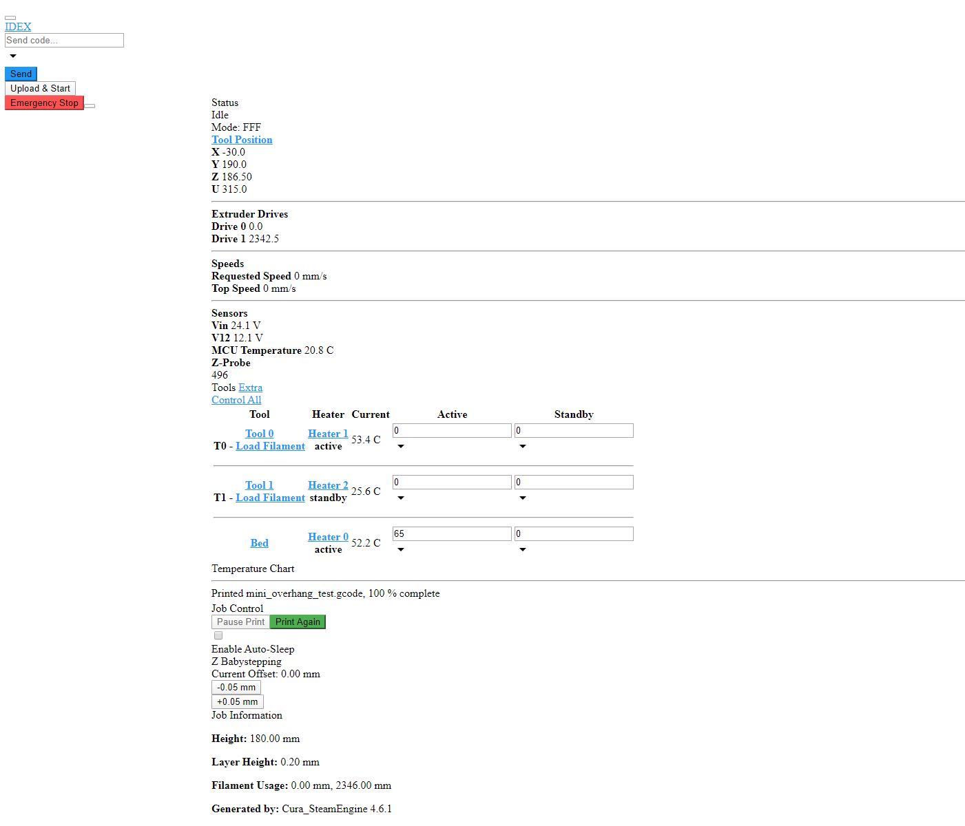
      Recently for some reason, my DWC looks like this after loading. After a couple of refresh or restart, the proper GUI can show up. I am using Chrome and a Duet3 running standalone mode with wired internet.
      6e3affe4-498b-47ee-ac42-0c33406c6800-image.png

      posted in Duet Web Control
      Ray11undefined
      Ray11
    • Short to ground question

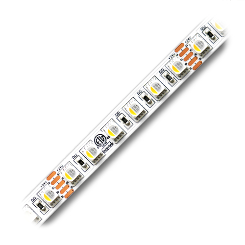
      I would like to install some LEDs on my printer. The LED has positive and negative traces pretty close to each other. I am wondering if a short to ground happening on the power supply side would damage the controller board?

      d74b94b4-1294-42cd-8a9e-66d5a5b05753-image.png

      posted in Duet Hardware and wiring
      Ray11undefined
      Ray11
    • RE: Panasonic Laser Probe for ABL

      Thanks for the info! I also asked a reseller of these probes and they say this type doesn't work on transparent objects. So I guess there isn't one probe that can tick all the boxes.

      posted in General Discussion
      Ray11undefined
      Ray11
    • Panasonic Laser Probe for ABL

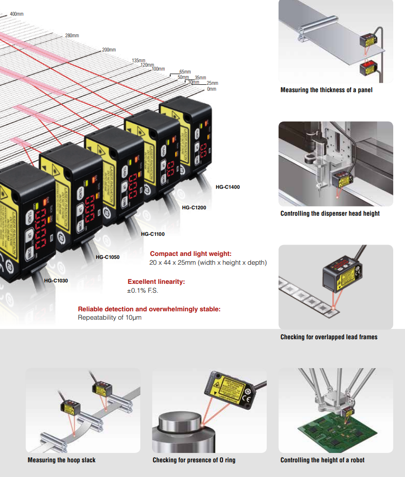
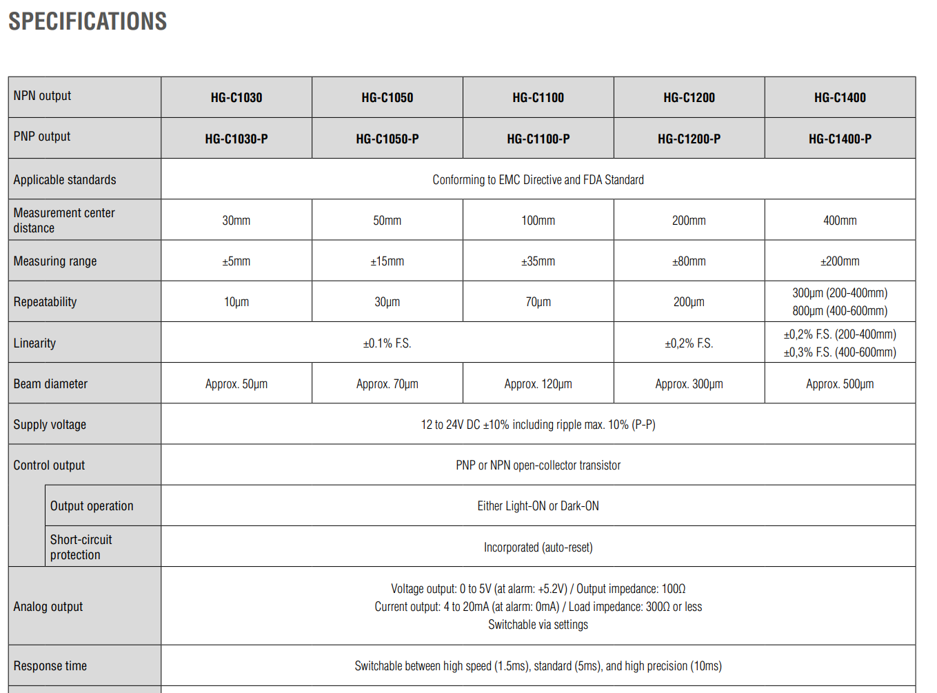
      I was looking for probes for ABL and found out Panasonic has a laser probe lineup. It seemed like it can probe on any surface and also have exact distance output. In theory, it can be set up like Markforged and also check the part. It would be really cool if it can directly scan the bed instead of probing individual points.
      I am wondering if anybody had tried it before or works in the industry and have some experience with these laser probes. They are expensive ($300+ on Digikey and $200+ on Alibaba) but if it can reliably probe the bed and part I think it is worth it.
      2a0cabb6-1056-40ef-83ea-ae50d9a51d23-image.png
      c95487e8-a225-4cc2-ae91-0dc3c4f08607-image.png

      posted in General Discussion
      Ray11undefined
      Ray11
    • Pulsing LED between Reset and SD slot on duet 3

      I am wondering what is the LED between Reset and SD slot indicate. It seemed like the wiring diagram did not show what is it for.

      posted in Duet Hardware and wiring
      Ray11undefined
      Ray11
    • RE: Duet3 and Pi issue

      Thank you, it seems like I put 2 S parameters in M106 which caused the issue.

      posted in Firmware installation
      Ray11undefined
      Ray11
    • Duet3 and Pi issue

      Hello, I ran into this weird issue that only the heater 0 is detected on DWC.
      de78bb1a-5f4c-4133-a457-63456875f027-image.png
      I am sure this should be a quick fix but I could not figure out how.
      Here is my Config.g

      ; Configuration file for Duet 3 (firmware version 3)
      ; executed by the firmware on start-up
      ;
      ; generated by RepRapFirmware Configuration Tool v2.1.8 on Wed Apr 01 2020 22:14:44 GMT-0500 (Central Daylight Time)
      
      ; General preferences
      G90                                             ; send absolute coordinates...
      M83                                             ; ...but relative extruder moves
      ;M550 P"duet3"                            ; set printer name
      M575 P1 B57600 S1
      
      ; Network
      M552 P0.0.0.0 S1                                ; enable network and acquire dynamic address via DHCP
      M586 P0 S1                                      ; enable HTTP
      M586 P1 S0                                      ; disable FTP
      M586 P2 S0                                      ; disable Telnet
      
      ; Drives
      M569 P0.0 S1 D3                                  ; physical drive 0.0 goes forwards
      M569 P0.1 S1 D3                                   ; physical drive 0.0 goes forwards
      M569 P0.2 S0 D3                                   ; physical drive 0.2 goes forwards
      M569 P0.3 S1 D3                                   ; physical drive 0.3 goes forwards
      M569 P0.4 S0 D3                                   ; physical drive 0.4 goes forwards
      M569 P0.5 S0 D3                                   ; physical drive 0.5 goes forwards
      M584 X0.0 U0.1 Y0.2 Z0.3 E0.4:0.5                    ; set drive mapping
      M350 X16 U16 Y16 Z16 E16:16 I1                      ; configure microstepping with interpolation
      M92 X200.00 U200.00 Y80.00 Z400.00 E420.00:420.00      ; set steps per mm
      M566 X900.00 U900.00 Y900.00 Z12.00 E120.00:120.00      ; set maximum instantaneous speed changes (mm/min)
      M203 X9000.00 U9000.00 Y6000.00 Z1500.00 E1200.00:1200.00 ; set maximum speeds (mm/min)
      M201 X1500.00 U1500.00 Y1500.00 Z1000.00 E250.00:250.00      ; set accelerations (mm/s^2)
      M906 X600 U600 Y1300 Z600 E600:600 I30                ; set motor currents (mA) and motor idle factor in per cent
      M84 S30                                         ; Set idle timeout
      
      ; Axis Limits
      M208 X-30 U26 Y0 Z0 S1                                ; set axis minima
      M208 X260 U316 Y190 Z186.7 S0                          ; set axis maxima
      
      ; Endstops
      M574 X1 P"io1.in" S1                                      ; configure sensorless endstop for low end on X
      M574 U2 P"io2.in" S1
      M574 Y2 P"!io5.in" S1                                      ; configure sensorless endstop for low end on Y
      M574 Z2 P"io6.in" S1                                      ; configure sensorless endstop for low end on Z
      M915 P0:1 S10 R1
      M915 P2 S10 R1
      
      ; Z-Probe
      M558 P1 I0 C"!io3.in" A5 R0.4 H6 F1300 T6000                 ; set Z probe type to switch and the dive height + speeds
      G31 P220 X0 Y0 Z0                            ; set Z probe trigger value, offset and trigger height
      ;G31 P{sensors.probes[0].value[0] + 30}
      ;G31 X0 Y0 Z0
      M557 X70:220 Y30:180 S75                        ; define mesh grid
      
      
      ; Heaters
      M570 S99999
      M308 S0 P"temp0" Y"thermistor" T100000 B4138    ; configure sensor 0 as thermistor on pin temp0
      M950 H0 C"out0" T0                              ; create bed heater output on out0 and map it to sensor 0
      M143 H0 S80                                    ; set temperature limit for heater 0 to 120C
      M307 H0 B0 S0.8                               ; enable bang-bang mode for the bed heater and set PWM limit
      M307 H0 A84.5 C473.8 D1.4
      M140 H0                                         ; map heated bed to heater 0
      M308 S1 P"temp1" Y"thermistor" T100000 B4138    ; configure sensor 1 as thermistor on pin temp1
      M950 H1 C"out1" T1                              ; create nozzle heater output on out1 and map it to sensor 1
      M143 H1 S240                                    ; set temperature limit for heater 1 to 240C
      M307 H1 B0 S1.00                                ; disable bang-bang mode for heater  and set PWM limit
      M307 H1 A593.7 C179.8 D9.3 V24.0
      M308 S2 P"temp2" Y"thermistor" T100000 B4138    ; configure sensor 2 as thermistor on pin temp2
      M950 H2 C"out2" T2                              ; create nozzle heater output on out2 and map it to sensor 2
      M143 H2 S240                                    ; set temperature limit for heater 2 to 240C
      M307 H2 B0 S1.00                                ; disable bang-bang mode for heater  and set PWM limit
      M307 H2 A532.1 C165.0 D10.3 V24.0
      M572 D0:1 S0.1:0.1								;Pressure Advance
      
      ; Fans
      M950 F0 C"out7" Q500                            ; create fan 0 on pin out4 and set its frequency
      M106 P0 L1.0 S0 H1 T60 S1.00                               ; set fan 0 value. Thermostatic control is turned on
      M950 F1 C"out8" Q500                            ; create fan 1 on pin out5 and set its frequency
      M106 P1 S0 H-1                                  ; set fan 1 value. Thermostatic control is turned off
      M950 F2 C"out4" Q500                            ; create fan 2 on pin out7 and set its frequency
      M106 P2 L1.0 S0 H2 T60 S1.0                               ; set fan 2 value. Thermostatic control is turned on
      M950 F3 C"out9" Q500                            ; create fan 3 on pin out6 and set its frequency
      M106 P3 S0 H-1                                  ; set fan 3 value. Thermostatic control is turned off
      
      ; Tools
      M563 P0 D0 H1 F0:1                              ; define tool 0
      G10 P0 X0 Y0 Z0                                 ; set tool 0 axis offsets
      G10 P0 R0 S0                                    ; set initial tool 0 active and standby temperatures to 0C
      M563 P1 D1 H2 X3 F0:3                              ; define tool 1
      G10 P1 U-0.0 Y1.0 Z-0.2                                 ; set tool 1 axis offsets
      G10 P1 R0 S0                                    ; set initial tool 1 active and standby temperatures to 0C
      
      ; Custom settings are not defined
      T0
      
      
      posted in Firmware installation
      Ray11undefined
      Ray11