Latest posts made by ScaraMan
-
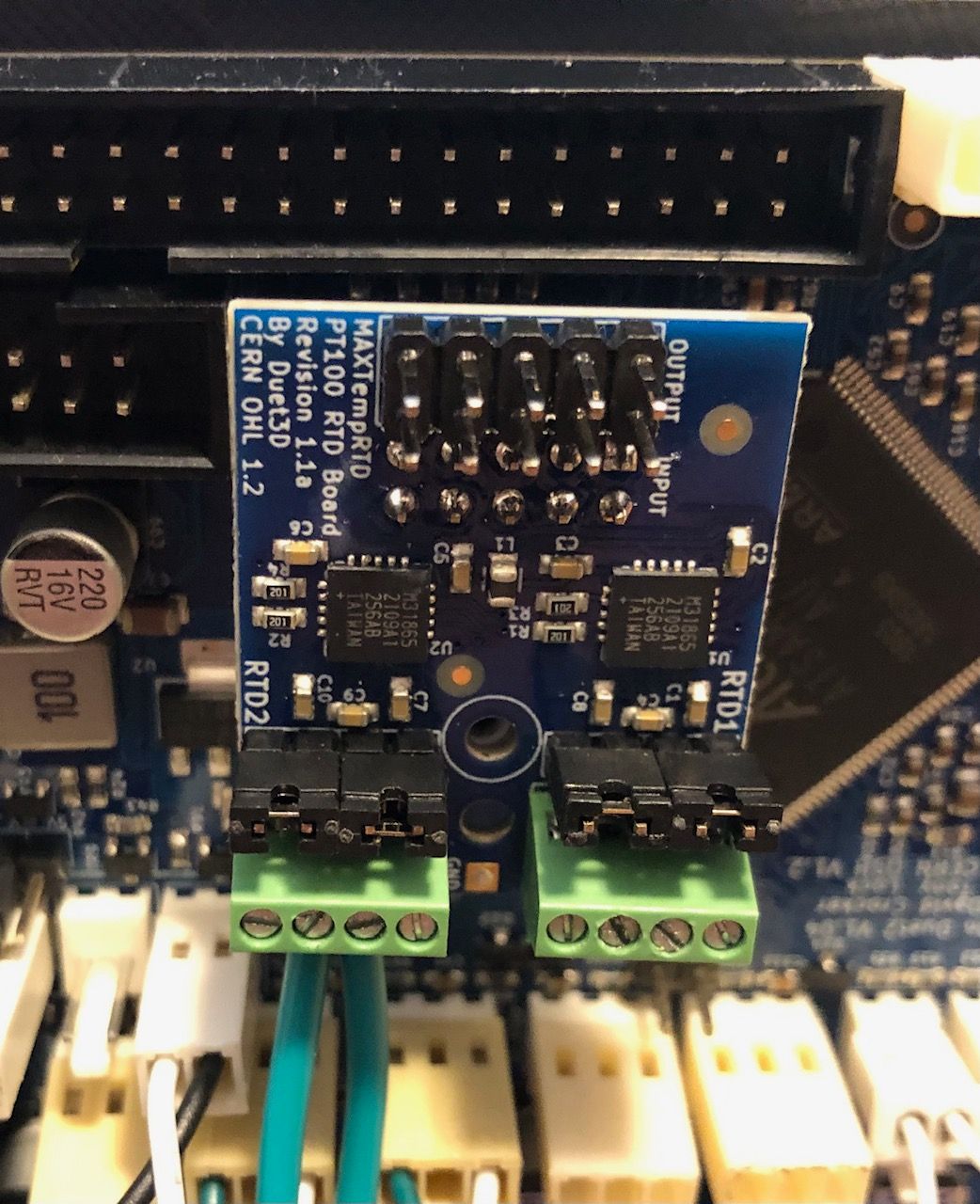
PT100 DAUGHTER BOARD, Reading 2000 c for Heat Bedposted in Duet Hardware and wiring
Hi
I recently purchased the PT100 Daughterboard latest version with jumpers.
I have some issues.
The reason why I bought this board, was to connect the Ultimaker 2 heatbed to the Duet wifi.
That’s all, but when I connect it reads 2000 C for the Bed, I am using rep rap firmware2.x
I followed the instructions on the web on how to configure firmware.
The 2 wires for power go to heatbed connector on Duet wifi , and the other 2 wires I have connected to PT 100 motherboard (2 and 3 on the first connector )
The jumpers are there on both connectors.
I am only using 1 connector for the heatbed only, not for my hotend ( since that is a e3d v6 no pt100 sensor )Can you please tell me how to fix this issue ??
How to properly configure ??Currently under the Heater section in config file I have this
M305 P0 X200 ; set thermistor + ADC parameters for heater 0
M143 H0 S65 ; set temperature limit for heater 0 to 80C
M305 P1 T100000 B4138 R4700 ; set thermistor + ADC parameters for heater 1
M143 H1 S260 ; set temperature limit for heater 1 to 260C -
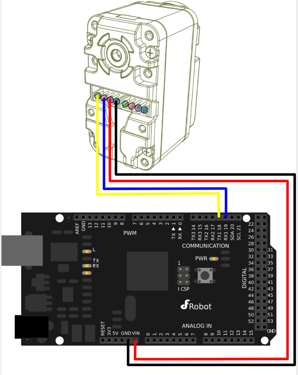
RE: Need help to connect Herkulex smart servos to the Duet wifiposted in Duet Hardware and wiring
hi
Yes, I have all those documents already, and have used the servos connected with Arduino uno and Arduino due.
I just want to know how can I use them with the Duet wifi ???
a sketch would be appreciated for the connections,
or since I know how to connect them to the Arduino board, is it possible to use the Arduino with the duet wifi ?? if so how ?? -
RE: Need help to connect Herkulex smart servos to the Duet wifiposted in Duet Hardware and wiring
here are the electrical specifications
Working Voltage: 7~12VDC(Optimized 7.4V)
Rated Current: 450mA @ 7.4V : 1.7kgf.cm
Communication Link: Full Duplex Asynchronous Serial(TTL Level), Binary Packet, Multi Drop
Multi control through Servo ID: 0 ~ 253, 254(Broadcast only)
Maximum Baud Rate: 0.67Mbps
Feedback: Position, Speed, Temperature, Load, Voltage etc.
Various Control Algorithm: PID, Feedforward, Trapezoidal Velocity Profile, Velocity Override, Torque Saturator & Offset, Overload Protection, Neutral Calibration, Dead Zone -
Need help to connect Herkulex smart servos to the Duet wifiposted in Duet Hardware and wiring
Hi Guys,
I have attached an image showing how the Herkulex smart servo is connected with an Arduino uno board ( RX is pin 11, and TX is pin 10 ), how can I connect the servo to the Duet wifi ??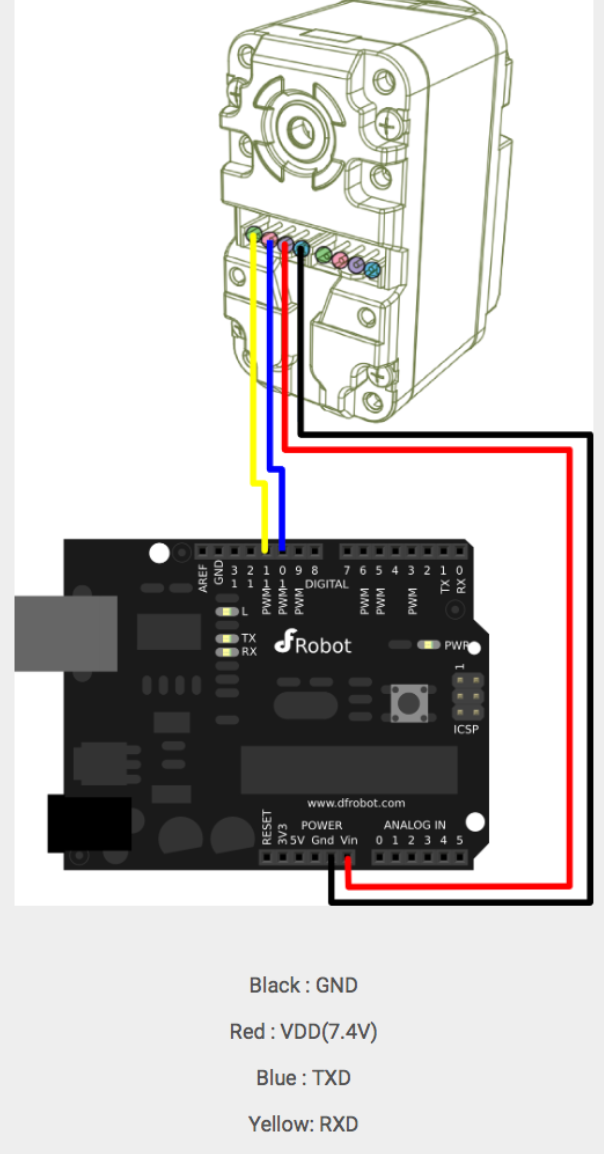
-
RE: How to connect Smart Servo to the Duet Wifiposted in General Discussion
Hi
I appreciate your help, thanks.
In order for the servos run, they require 7.4 VDC
I will have to use a drop down converter from 24V TO 7.4
If you have an example of the wiring or a simple sketch , that would be very
Much appreciated -
How to connect Smart Servo to the Duet Wifiposted in General Discussion
Hi
I am currently building a Scara Robot and planning to use the Duet Wifi
as my hardware controller for the stepper motors X,Y and Z.
I am planning to use 2 smart servos Herkulex DRS -101 for my Robot Gripper since I already have them, and was wandering how can I implement these to work with the Duet Wifi board ???
The servos can be daisy chained
-
RE: Using a 4th (Rotary) Axisposted in CNC
@dc42 Hi David, I am trying to get in contact with you concerning SCARA.
I have posted a link on the forum , can you please have a look at it, I need your opinion.
Thank youhere is the link
https://forum.duet3d.com/topic/14114/scara-robot-want-to-know-if-duet-wifi-is-the-right-choice?_=1580465871679 -
SCARA Robot - want to know if DUET WIFI is the right choiceposted in General Discussion
Hello all ,
I have built a Scara robot similar to JJRobots , with improved design modifications- for testing only. Once I have a board that can
Make it work , I will port it to a more high end build SCARA.
I have tried using marlin firmware to control it, but I never succeed
I am using an Ultimaker 2 controller board to run the motors and end stops only .For now. It can home the arms when I use pronterface but after that it goes
Crazy , I have tried several times, changing home offsets, scara offsets, but never work according to my setup. I give up. !
I want to know if I should get the Duet wifi for my SCARA .
I am already using the DUET wifi for my printer and I am very pleased.
I came across the Scarlett SCARA , and I noticed he’s using the DUET and works fine. I have attached a TOP VIEW with some dimensions of the SCARA and a picture, any help would be much appreciated. Thanks !


-
Have to run G code file twice to begin print at correct heightposted in General Discussion
Hi guys
I have this issue where I send the g code file to the duet wifi, and all is well until it starts to print. The nozzle tip is quite a few mm above the heatbed, I cancel, start another, then its perfect. Any clue why this is ?
I have posted below, config, home all, home z, and a snippet from the beginning of the code file
; Configuration file for Duet WiFi (firmware version 2.03)
; executed by the firmware on start-up
;
; generated by RepRapFirmware Configuration Tool v2.1.3 on Wed Nov 27 2019 02:27:21 GMT-0500 (EST); General preferences
G90 ; send absolute coordinates...
M83 ; ...but relative extruder moves
M550 P"ALPHA 300" ; set printer name; Network
M552 S1 ; enable network
M586 P0 S1 ; enable HTTP
M586 P1 S0 ; disable FTP
M586 P2 S0 ; disable Telnet; Drives
M569 P0 S0 ; physical drive 0 goes backwards
M569 P1 S0 ; physical drive 1 goes backwards
M569 P2 S0 ; physical drive 2 goes backwards
M569 P3 S0 ; physical drive 3 goes backwards
M584 X0 Y1 Z2 E3 ; set drive mapping
M350 X16 Y16 Z16 E16 I1 ; configure microstepping with interpolation
M92 X80.00 Y80.00 Z1600.00 E311.00 ; set steps per mm
M566 X900.00 Y900.00 Z12.00 E120.00 ; set maximum instantaneous speed changes (mm/min)
M203 X6000.00 Y6000.00 Z300.00 E4200.00 ; set maximum speeds (mm/min)
M201 X500.00 Y500.00 Z20.00 E250.00 ; set accelerations (mm/s^2)
M906 X1050 Y1050 Z1250 E1050 I30 ; set motor currents (mA) and motor idle factor in per cent
M84 S30 ; Set idle timeout; Axis Limits
M208 X0 Y0 Z0 S1 ; set axis minima
M208 X300 Y300 Z190.19 S0 ; set axis maxima; Endstops
M574 X1 Y1 Z2 S0 ; set active low end endstops; Z-Probe
;M558 P0 H5 F120 T6000 ; disable Z probe but set dive height, probe speed and travel speed
;M557 X15:215 Y15:195 S20 ; define mesh grid; Heaters
M305 P0 T100000 B4138 R4700 ; set thermistor + ADC parameters for heater 0
M143 H0 S80 ; set temperature limit for heater 0 to 80C
M305 P1 T100000 B4138 R4700 ; set thermistor + ADC parameters for heater 1
M143 H1 S260 ; set temperature limit for heater 1 to 260C; Fans
M106 P0 S1 I0 F500 H-1 ; set fan 0 value, PWM signal inversion and frequency. Thermostatic control is turned OFF
M106 P1 S1 I0 F500 H1 T45 ; set fan 1 value, PWM signal inversion and frequency. Thermostatic control is turned ON
M106 P2 S1 I0 F500 H-1 ; set fan 2 value, PWM signal inversion and frequency. Thermostatic control is turned OFF; Tools
M563 P0 S"NOZZLE " D0 H1 F0 ; define tool 0
G10 P0 X0 Y0 Z0 ; set tool 0 axis offsets
G10 P0 R0 S0 ; set initial tool 0 active and standby temperatures to 0C; Custom settings are not defined
————————————————————————————————————————
; homeall.g
; called to home all axes
;
; generated by RepRapFirmware Configuration Tool v2.1.3 on Wed Nov 27 2019 02:27:21 GMT-0500 (EST)
G91 ; relative positioning
G1 H2 Z5 F300 ; lift Z relative to current position
G1 H1 X-305 Y-305 F1800 ; move quickly to X and Y axis endstops and stop there (first pass)
G1 H2 X5 Y5 F6000 ; go back a few mm
G1 H1 X-305 Y-305 F360 ; move slowly to X and Y axis endstops once more (second pass)
G1 H1 Z195.19 F300 ; move Z up stopping at the endstop
G90 ; absolute positioning
G92 Z190.19 ; set Z to axis minimum (you may want to adjust this); Uncomment the following lines to lift Z after probing
;G91 ; relative positioning
;G1 S2 Z5 F100 ; lift Z relative to current position
;G90 ; absolute positioning————————————————————————————————————————
; homez.g
; called to home the Z axis
;
; generated by RepRapFirmware Configuration Tool v2.1.3 on Wed Nov 27 2019 02:27:21 GMT-0500 (EST)
G91 ; relative positioning
G1 H2 Z5 F300 ; lift Z relative to current position
G1 H1 Z195.19 F300 ; move Z up until the endstop is triggered
G90 ; absolute positioning. added extra line could remove for testing
G92 Z190.19 ; set Z position to axis minimum (you may want to adjust this); Uncomment the following lines to lift Z after probing
;G91 ; relative positioning
;G1 H2 Z5 F100 ; lift Z relative to current position
;G90 ; absolute positioning————————————————————————————————————————
;FLAVOR:RepRap
;TIME:44156
;Filament used: 9.62041m
;Layer height: 0.2
;Generated with Cura_SteamEngine 3.6.0
T0
M190 S60
M104 S210
M109 S210
M82 ;absolute extrusion mode
G90 ; Absolute Position
G28 ; Home ALL axis
G1 X30 Y30 Z170
G92 E0 ; Reset extruder
G1 X30 Y30 F4000 ;move X/Y to front of printer
G1 Z15.0 F9000 ;move the platform to 15mm
G4 5000
G92 E0 ;zero the extruded length
G1 F200 E50 ;extrude 10 mm of feed stock
G4 10000
G92 E0 ;zero the extruded length again
G4 1000
M83 ;relative extrusion mode
G1 F1500 E-6.5
;LAYER_COUNT:401
;LAYER:0
M107
G0 F7500 X165.65 Y76.023 Z0.16
;TYPE:SKIRT
G1 F1500 E6.5
G1 F900 X165.918 Y75.542 E0.00552
G1 X166.252 Y75.104 E0.00553
G1 X166.647 Y74.72 E0.00553
G1 X167.093 Y74.396 E0.00553
G1 X167.581 Y74.141 E0.00552