Great, that just helped me.
Now all fan positions are switched to 12V.
Thanks for the support.
Great, that just helped me.
Now all fan positions are switched to 12V.
Thanks for the support.
Actually, I would like to have all fan slots on 12 V, 4 of them always switched on and a space for the component fan running on software PWM.
@Phaedrux said in Duet 2 Ethernet 12V Fan wiring:
Ok well you can't measure anything usable off the fan ports unless you have configured them. The always on fan ports should measure with the same voltage as the Vfan pin is being fed.
Ah OK I understand. So I have to configure each fan individually. Do you have any instructions on how to configure the fans for the 12 V?
@Phaedrux said in Duet 2 Ethernet 12V Fan wiring:
Ok, and how are your fans configured when you're measuring them?
So far I have only connected the buck converter to the 12V + pin on the jumper slot as shown in the top picture. I have not yet made another active config in the firmware.
@Phaedrux said in Duet 2 Ethernet 12V Fan wiring:
What pins are you actually checking? There is nothing labeled port 1 2 3 4 5, so I'm not sure what you're measuring.
I measured the yellow framed FAN pins.
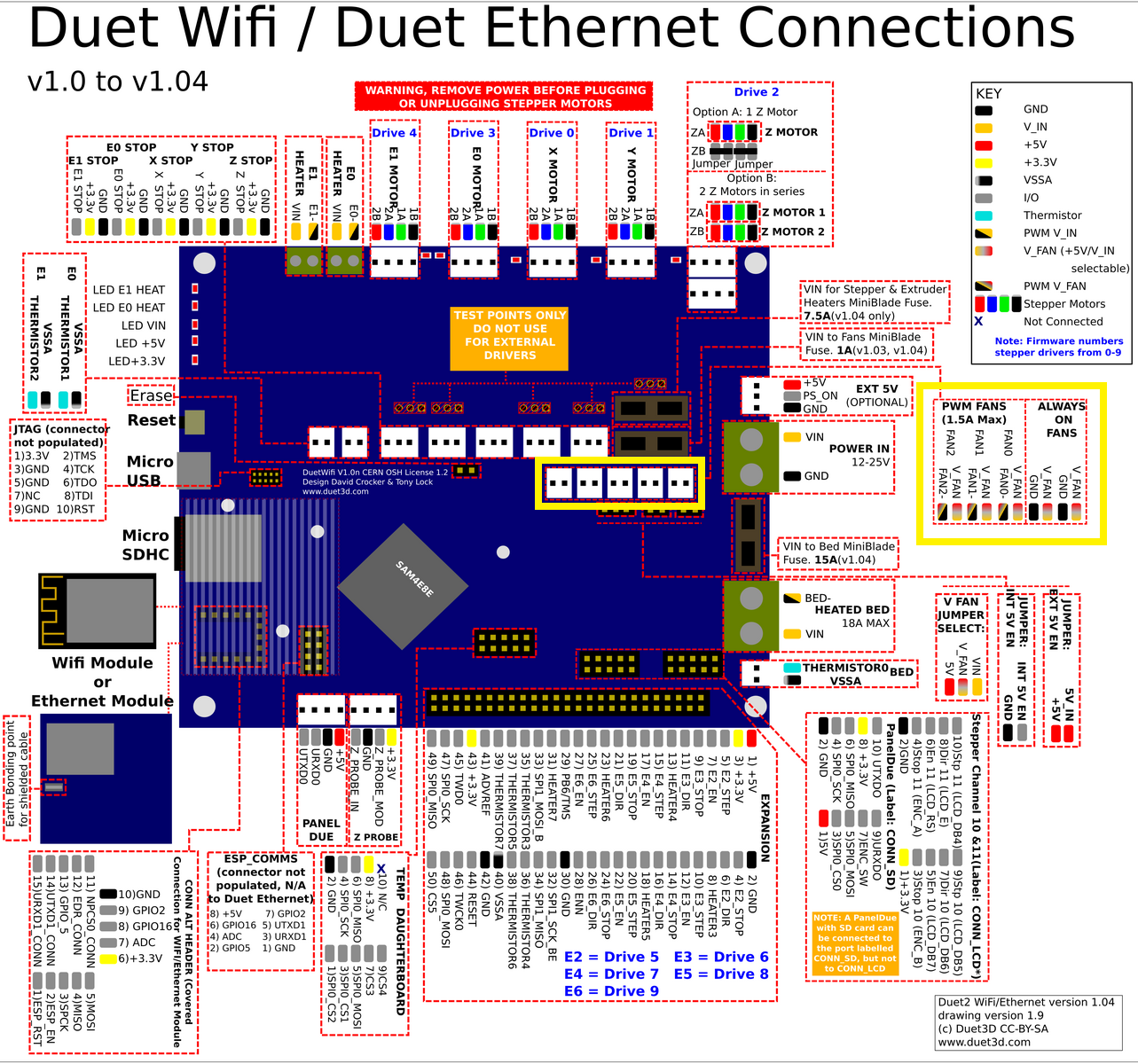
is there any of the Duet employees here who can give me a comment on why this is so?
So I did it with the Buck converter. I then measured the individual fan ports with a multimeter. However, I see at port 1 and 2 12V at port 3 the voltage only jumps back and forth. With port 4 this is stable again at 12V and with port 5 is a voltage of 2.4V only indicated to me?
what can this cause?
Hello everybody,
I want to operate all 5 fan slots on the Duet 2 Ethernet to 12V. If I understand that correctly, I have to remove the jumper and connect the 12V + cable from the Stepdown Converter output to the V_Fan_Pin in the middle as in the picture below. Is that correct so far? What is outlined in yellow with the 2 jumpers on the right, do they stick or do they have to be removed? Or what are these jumpers for? On the pinout I can not understand what is meant by the two (INT 5V EN and EXT 5V EN) jumpers or what they are for?
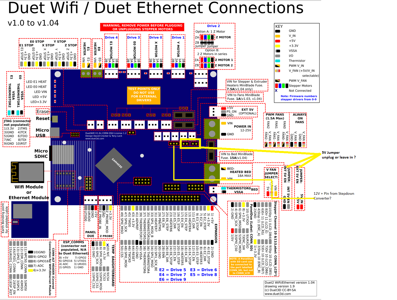
When I ask my question, I refer a little to this article here.
https://forum.duet3d.com/topic/4917/wiring-issues-5-v-12-v-waterpump-24-v-psu
Basically, it should be similar to the structure here, only since I actually want to connect 5x 12V fans.
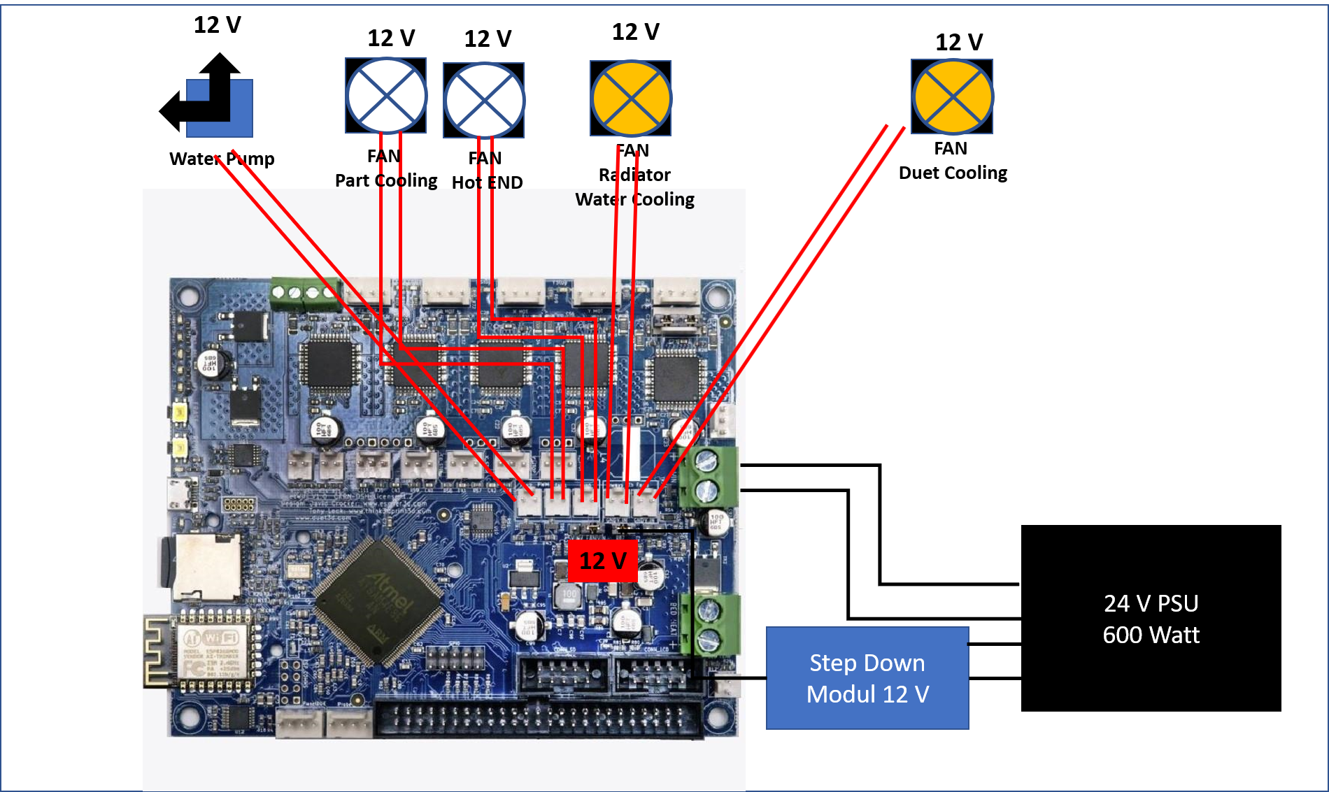
Thank you for your help or feedback on my question.
best regards
Zappelmann
thank you for the fast reaction.
Good Morning all,
I seem to have encountered exactly the same sd-card problem with my new Duet 2 Ethernet V1.04c board.
I wanted to set up the board last Saturday with a friend who already has two of these boards in operation and now I seem to have encountered exactly the same problem as described here.
I have read and checked this article carefully and implemented all advice and inquiries accordingly. Unfortunately, however, this was also unsuccessful. Therefore, I have now collected all the data that you may need for a guarantee exchange. Unless you have another idea how to solve the problem.
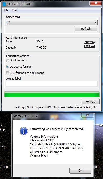
I downloaded the SD card content from your Github pages and copied it to the formatted card.
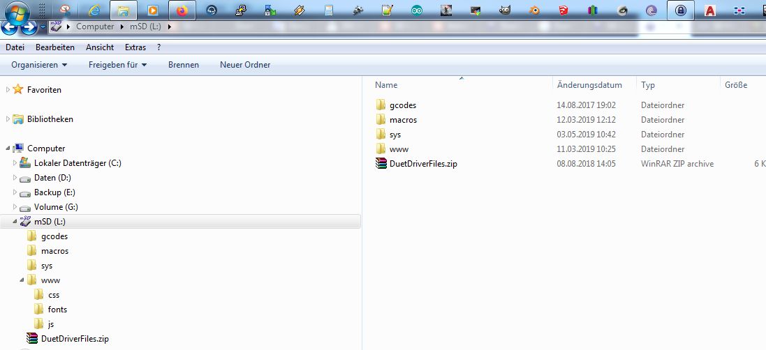
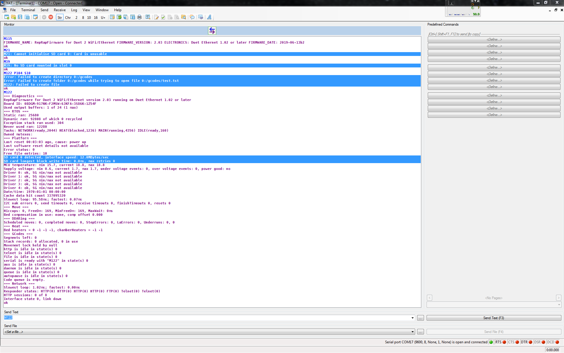
I also did this procedure with the original SD card and another SD card. With both I get the same feedback from YAT as can be seen in the course.

I also removed the Ethernet module to take a picture of the connections. Unfortunately, I don't have a camera that is so good for taking extremely high-resolution pictures. I hope you can see something on it.
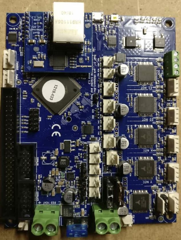
It would be nice if you should have another idea what it could be to give me feedback in a timely manner. Otherwise I would be grateful for a quick guarantee exchange.
please let me know if you need anything else from me.
thank you
Good Morning all,
I seem to have encountered exactly the same problem with my new Duet 2 Ethernet V1.04c board. After reading this article carefully and checking everything, I would like to have a guarantee exchange. How do I do this?
I wanted to set up the board last Saturday with a friend who already has two of these boards in operation and now I seem to have encountered exactly the same problem as described here.

I downloaded the SD card content from your Github pages and copied it to the formatted card.


I also did this procedure with the original SD card and another SD card. With both I get the same feedback from YAT as can be seen in the course.

I also removed the Ethernet module to take a picture of the connections. Unfortunately, I don't have a camera that is so good for taking extremely high-resolution pictures. I hope you can see something on it.

It would be nice if you should have another idea what it could be to give me feedback in a timely manner. Otherwise I would be grateful for a quick guarantee exchange.
please let me know if you need anything else from me.
thank you