Behavior of drivers at high speeds
-
Two suggestions:
-
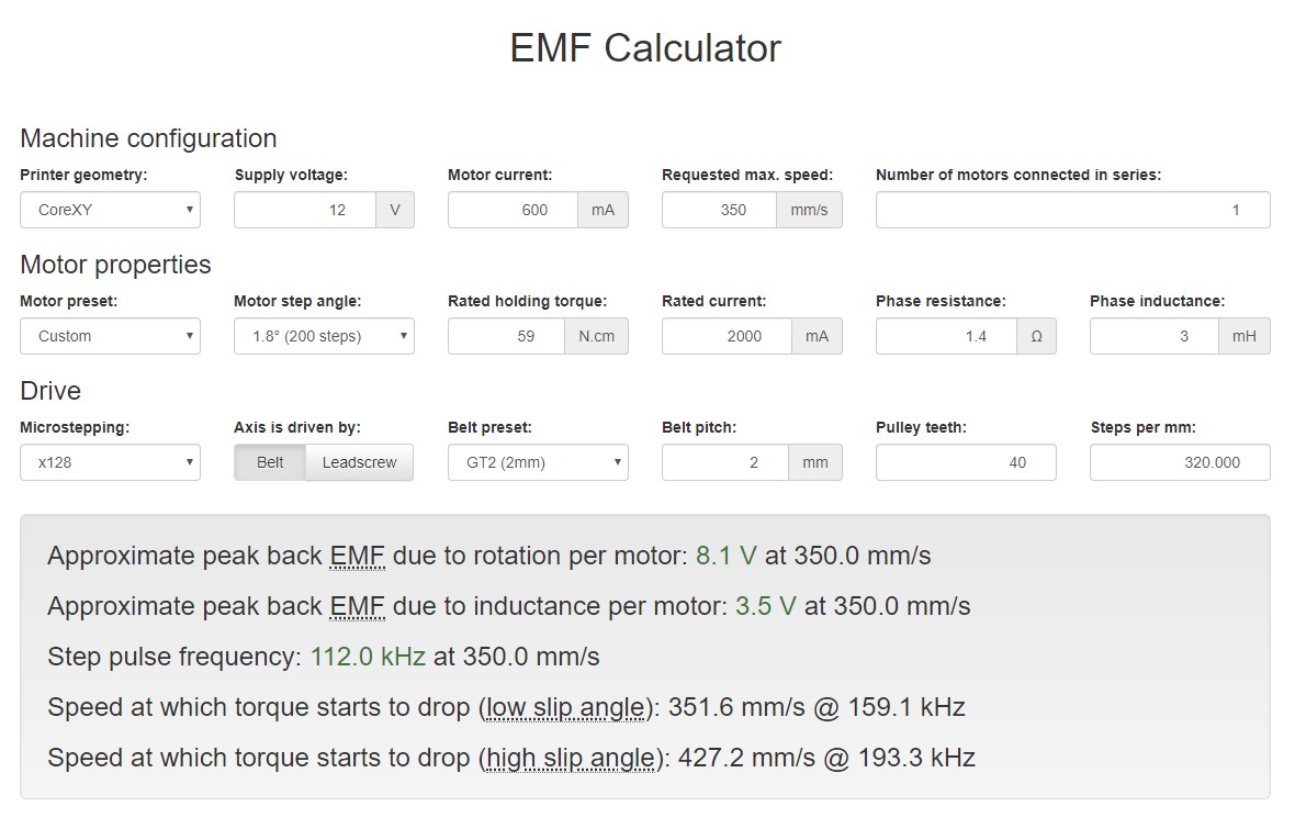
Use the back emf calculator at reprapfirmware.org to check that the driver supply voltage is high enough to maintain torque at those speeds. If it isn't, not only will you lose torque but also the motors will be noisy because the current waveform will be clipped.
-
If that isn't the problem, try x32 or x64 microstepping instead. Interpolating isn't accurate during acceleration.
Duet WiFi hardware designer and firmware engineer
Please do not ask me for Duet support via PM or email, use the forum
http://www.escher3d.com, https://miscsolutions.wordpress.com -
-
@dc42 Does the Duet board support 32 or 64:1 ustepping without interpolation?
-
@mrehorstdmd interpolation on the 2660 drivers can only be used with 16x microstepping. To enable interpolation, you must select 16x and set I to 1. If you select 32, 64, or 256 stepping, you are selecting true 1/256th microstepping, etc.
-
@bot Great! I will try tweaking the config file. Thanks!
-
@dc42 Is there any reason to use interpolated microstepping if the drivers can do uninterpolated microstepping to 256:1?
-
@mrehorstdmd said in Behavior of drivers at high speeds:
@dc42 Is there any reason to use interpolated microstepping if the drivers can do uninterpolated microstepping to 256:1?
Depends on the travel speed and your steps per mm, but if you use 256x (non-interpolated) then you could run into the maximum step pulse frequency of the board/firmware. I think that's currently around 120Khz but check because it used to be 200 Khz.
If it helps, using 256x on my extruders which have around 400 steps per mm, I hit the limit using retraction speed above 1800mm/min (30mm/sec) so with say 80 steps per mm you should be OK up to around 150mm/sec.
-
I used the back EMF calculator to calculate speed limits based on the motors I am using, current, pulleys, etc. and found that with a 12V power supply, torque slip is the main limiting factor in maximizing speed at all microstep settings from 16:1 up to 128:1. At those settings, maximum speed is limited to about 350 mm/sec. At 256:1 the pulse rate exceeds the controller's 120 KHz limit.
I composed a gcode file to move the mechanism at 100 mm/sec and 350 mm/sec at 16, 32, 64, and 128:1 ustepping. Video of the test is here.
Here's the test gcode:
; filename: '12V 100 350 mmps'
M564 H0 S0 ; enable motion without homing
M350 X16 Y16 Z16 I0 ; Configure 16:1 microstepping with no interpolation
M92 X40.00 Y40.00 Z40.00 ; Set steps per mmG28 Y F3000
G28 X
G01 F6000; 100 mm/secG01 X725 Y300
G01 X0 Y1025
G01 X725 Y1025
G01 X725 Y300G01 F21000; 350 mm/sec
G01 X0 Y1025
G01 X725 Y1025
G01 X725 Y300M350 X32 Y32 Z16 I0 ; Configure 32:1 microstepping with no interpolation
M92 X80.00 Y80.00 Z40.00 ; Set steps per mmG01 F6000; 100 mm/sec
G01 X0 Y1025
G01 X725 Y1025
G01 X725 Y300G01 F21000; 350 mm/sec
G01 X0 Y1025
G01 X725 Y1025
G01 X725 Y300M350 X64 Y64 Z16 I0 ; Configure 64:1 microstepping with no interpolation
M92 X160.00 Y160.00 Z40.00 ; Set steps per mmG01 F6000; 100 mm/sec
G01 X0 Y1025
G01 X725 Y1025
G01 X725 Y300G01 F21000; 350 mm/sec
G01 X0 Y1025
G01 X725 Y1025
G01 X725 Y300M350 X128 Y128 Z16 I0 ; Configure 128:1 microstepping with no interpolation
M92 X320.00 Y320.00 Z40.00 ; Set steps per mmG01 F6000; 100 mm/sec
G01 X0 Y1025
G01 X725 Y1025
G01 X725 Y300G01 F21000; 350 mm/sec
G01 X0 Y1025
G01 X725 Y1025
G01 X725 Y300M350 X16 Y16 Z16 I0 ; Configure 16:1 microstepping with no interpolation
M92 X40.00 Y40.00 Z40.00 ; Set steps per mmG01 F6000; 100 mm/sec
G01 X0 Y1025
G01 X725 Y1025
G01 X725 Y300G01 F21000; 350 mm/sec
G01 X0 Y1025
G01 X725 Y1025
G01 X725 Y300I hear a definite decrease in noise at 100 mm/sec when it goes from 16:1 to 32:1 or higher, but 32;1, 64:1, and 128:1 all sound about the same. At 350 mm/sec I don't hear any differences at any microstepping levels.
The single motor motion (diagonal) is a lot quieter than the dual motor motion (X and Y), but only one motor is turning, so less vibration as expected.
I'm trying to make the mechanism run quietly at speeds like 350-500 mm/sec. Maybe that's just not possible using 2 phase stepper motors?
-
0.9deg motors may be quieter, but they also need more drive voltage.
Have you tried reducing the motor current? If the calculator estimates the drive voltage runs out at 350mm/sec then it might happen at a lower speed. There should be a noticeable increase in noise when the speed exceeds the limit. You could also try turning your 12V PSU up to 14V if it is adjustable.
Duet WiFi hardware designer and firmware engineer
Please do not ask me for Duet support via PM or email, use the forum
http://www.escher3d.com, https://miscsolutions.wordpress.com -
@dc42 I played with motor current and found that if I set it to 500 mA, the torque is a bit too low to drive the mechanism reliably. At 600 mA it seems to work well. The motors are rated for 2A.
I've tried using 24V and found not much change in noise level, though it lets the mechanism run faster.
I have some 3 phase stepper drivers so may look for some cheap 3 phase motors and see if things improve. Otherwise, maybe going to 5 phase steppers will drive it quietly at high speed.
-
It occured to me that since I have excess torque and excess resolution available from the motors, and that they run quietly if I keep the speed down to <2 revs/sec, I can use pulleys to gear the mechanism up so that 1 rev per sec or so will drive the mechanism at 500 mm/sec. Motor torque is higher at lower rotation speeds and I can crank up the current if necessary to get enough torque to drive the mechanism.
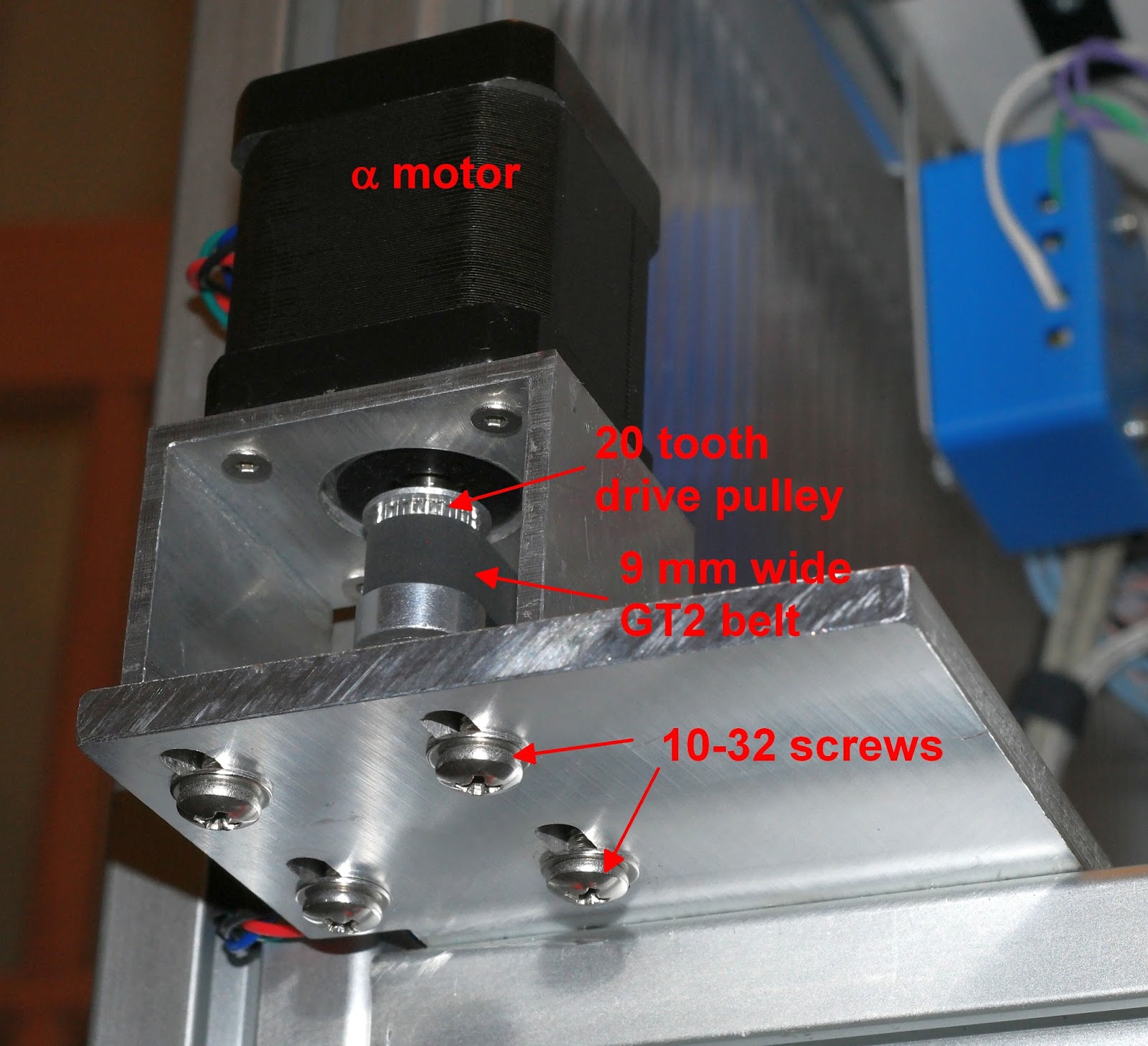
I ordered a set of pulleys with a closed loop belt that will provide a 1:5 step up in speed. I'm redesigning the motor mounts to accommodate the 80 tooth drive pulleys. There will be separate pulley mounts that drive the corexy mechanism- a 16 tooth driven pulley from the motor, and using the 40 tooth drive pulleys that the mechanism is currently designed around. 1 rev of the motor will spin the 40 tooth drive pulley 5x, for 400 mm displacement. The motor and corexy drive pulley mounts will be separate pieces, so I'll tension the corexy belts by moving the corexy drive pulley mounts, then tension the loop belts by moving the motor mounts.

I'm trying to get this done in time for the Milwaukee Makerfaire in mid September, but parts are coming from China, so who knows if they will arrive in time.
-
@mrehorstdmd This is an idea that I've been thinking about for a long time, although not for the same reasons. My thinking is that it would allow one to use higher belt tension on the main belt that the stepper motor bearings might not otherwise tolerate. Whether or not this would be beneficial, is of course not known. So I will be following your journey with interest.
-
@deckingman can you support the motor shaft with an appropriate bearing at the other end or is it not long enough?
-
@t3p3tony said in Behavior of drivers at high speeds:
@deckingman can you support the motor shaft with an appropriate bearing at the other end or is it not long enough?
I could maybe just about do it with the Alpha motors but not the Beta motors because I have stacked belts and the pulleys are at the end of the shafts on those motors.
-
@deckingman if you make the motor mounts with different vertical dimensions, by about 12-15 mm, the pulleys can mount right up against the motors.
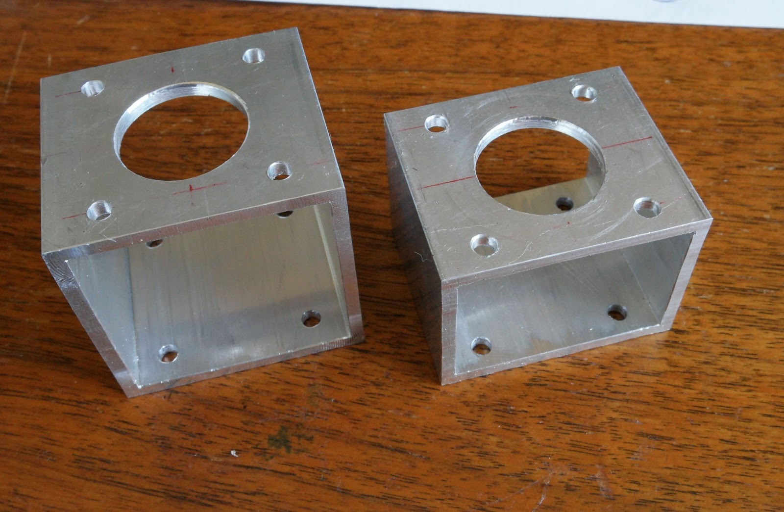
I used off-the-shelf 2" x 2" and 2" x 1.5" tubing.
The pulley is mounted in the same position relative to the motor on the B motor.
-
@mrehorstdmd Can't be done on my machine. Or rather, it could be done but I'd have to find a different method to tension the belts, as well as redesign the idler pulley mounts and gantries. All in all, it would likely be easier to mount the motors "remotely".
It'll have to wait in any case because I've got far too many other things to get on with right now. -
I rebuilt the mechanism with the 1:5 drive step-up pulleys and installed a Duet Wifi controller.
The result is mixed- the step up keeps the motor speed low even though the mechanism moves at 500 mm/sec, and I can use 256:1 uninterpolated microstepping. I'm having two problems- a lot of the remaining noise seems to be from the bearings in the pulleys and the belt teeth making a slight zipping sound on the small diameter, smooth pulley surfaces, and the torque from the motors is just enough to make the mechanism work, but if I push the acceleration or jerk a little too high, it starts skipping steps. That's without the magnet dragging against the bottom of the table and a ball in sand. The motors hiss a lot, too, though I adjusted the F parameter in the motor configuration- I've got the current cranked up to 1800 mA (2A motors) to get adequate torque.
All testing has been done with a 12V power supply. I'll try with 24V to see if anything improves.
I think I need to reduce the step-up to 1:4 to recover some of the torque, and use larger diameter or maybe toothed pulleys to reduce the belt noise. I think larger diameter pulleys would be the better way to go. The UHMW bearings in the magnet carriage are a little tight, so I'm going to cut some new ones out of PTFE and make them a little looser to reduce drag.
I'll post a test video later today.
-
I would think 24v would help a lot.
-
24V didn't help much.
I redesigned the mounts to fit the NEMA-23 motors I originally used in the sand table. The NEMA-17 motors were rated for 0.59 Nm holding torque and the NEMA-23s are rated for 1.27 Nm. I'll bore out the 80 tooth pulleys for the NEMA-23 1/4" shaft and test it later today.
The zippy noise seems to be coming from the belt teeth hitting the small, smooth pulley surfaces, so I'm going to try twisting the belts and see if they run quieter with the back sides of the belts riding on the pulleys.
The sand table is going to be exhibited at the Milwaukee MakerFaire next weekend, so if this 1:5 step-up stuff isn't working by Tuesday, I'll fall back to the NEMA-17 direct drive. At the MakerFaire, the noise doesn't matter and will probably be inaudible over the ambient noise at the event.
-
The NEMA-23 motors work fine with the 1:5 step up. The sound of the UHMW bearings sliding on the t-slot is now a significant portion of the noise, most of the rest being the zip-zip sound that I think is coming from the belt teeth hitting the pulleys. I'll try putting twists in the belts tomorrow.
The NEMA-23 motors seem to produce less of the hiss type noise that the NEMA-17 motors were producing.
-
Update: success!
The combo of 256:1 ustepping, 1:5 drive step-up (which divides torque by 5, hence NEMA-23 motors), and twisting the belts has quieted the mechanism to the point where the biggest noises come from the ball bearings in the pulleys and the sliding noise from UHMW bearing blocks on the X and Y axes. There's no discernable motor or belt noise at all. The motors spin at 1.25 revs/sec when the mechanism is running at 500 mm/sec.
Video here: https://vimeo.com/360320863
I did the first test with the whole table assembled at the Milwaukee Makerfaire this weekend and it was less than successful. The problem was high friction in the X axis causing the pattern to shift. I had lubed the X axis with some silicone lubricant but it only lasted a couple hours before the pattern shifting started.
I'm working on that problem now.