Duet3D Logo Duet3D
    • Tags
    • Documentation
    • Order
    • Register
    • Login

    Connecting multiple Z probes for multiple independent Z axis

    Scheduled Pinned Locked Moved
    Duet Hardware and wiring
    3
    17
    1.7k
    Loading More Posts
    • Oldest to Newest
    • Newest to Oldest
    • Most Votes
    Reply
    • Reply as topic
    Log in to reply
    This topic has been deleted. Only users with topic management privileges can see it.
    • georgepaulundefined
      georgepaul
      last edited by

      Have you guys checked out the ZideX 3D printer.
      Its awesome.

      I thought i would build a similar one but with two probes to home each independent Z axis.

      This calls for two probe pins that I believe the DuetWifi doesn't have. Does anyone know a hack around it? I am thinking of two inductive sensors for the two Z axis.

      dc42undefined 1 Reply Last reply Reply Quote 0
      • dc42undefined
        dc42 administrators @georgepaul
        last edited by

        You have several options. To use the Z probe instead of multiple endstop switches, see https://duet3d.dozuki.com/Wiki/Bed_levelling_using_multiple_independent_Z_motors. To use multiple endstop switches if running RepRapFirmware 2, see https://duet3d.dozuki.com/Guide/Independent+Z+motors+and+endstop+switches/18?lang=en. Or if running RepRapFirmware 3 see https://duet3d.dozuki.com/Wiki/RepRapFirmware_3_overview#Section_M574

        Duet WiFi hardware designer and firmware engineer
        Please do not ask me for Duet support via PM or email, use the forum
        http://www.escher3d.com, https://miscsolutions.wordpress.com

        georgepaulundefined 1 Reply Last reply Reply Quote 0
        • georgepaulundefined
          georgepaul @dc42
          last edited by

          @dc42 what about putting two probes for each Z?? is that possible??

          dc42undefined 1 Reply Last reply Reply Quote 0
          • dc42undefined
            dc42 administrators @georgepaul
            last edited by

            @georgepaul said in Connecting multiple Z probes for multiple independent Z axis:

            @dc42 what about putting two probes for each Z?? is that possible??

            That doesn't make sense to me. You only need one Z probe. But some people use 2 endstop switches, one for each motor.

            Duet WiFi hardware designer and firmware engineer
            Please do not ask me for Duet support via PM or email, use the forum
            http://www.escher3d.com, https://miscsolutions.wordpress.com

            georgepaulundefined 1 Reply Last reply Reply Quote 0
            • georgepaulundefined
              georgepaul @dc42
              last edited by

              @dc42 since the extruders are independent, and z axis and x axis will also be independent. we will need two probes right?!

              1 Reply Last reply Reply Quote 0
              • dc42undefined
                dc42 administrators
                last edited by

                @georgepaul said in Connecting multiple Z probes for multiple independent Z axis:

                ZideX

                I think I see what you mean. That printer design has two independent extruders, each on its own X carriage, and the height of each X carriage is controlled by a separate Z motor. Correct?

                In RepRapFirmware 2 you can switch between different types of Z probe using M558, and some types have their own G31 settings. RepRapFirmware 3 will be more versatile. You can already configure multiple Z probes in RRF3 (each with its own type and G31 parameters), all that's missing is a new M-code to switch between them.

                With either firmware, you can use the tool change files to select the Z probe you want to use and to switch height maps.

                Duet WiFi hardware designer and firmware engineer
                Please do not ask me for Duet support via PM or email, use the forum
                http://www.escher3d.com, https://miscsolutions.wordpress.com

                1 Reply Last reply Reply Quote 0
                • georgepaulundefined
                  georgepaul
                  last edited by

                  what about on the hardware side... where can i put the additional probe pins?

                  dc42undefined 1 Reply Last reply Reply Quote 0
                  • dc42undefined
                    dc42 administrators @georgepaul
                    last edited by

                    @georgepaul said in Connecting multiple Z probes for multiple independent Z axis:

                    what about on the hardware side... where can i put the additional probe pins?

                    On Duet 2 you can connect digital-output Z probes to any endstop input as well as to the Z probe connector. On Duet 3 you can connect them to any of the nine IO_x connectors.

                    Duet WiFi hardware designer and firmware engineer
                    Please do not ask me for Duet support via PM or email, use the forum
                    http://www.escher3d.com, https://miscsolutions.wordpress.com

                    1 Reply Last reply Reply Quote 0
                    • georgepaulundefined
                      georgepaul
                      last edited by

                      so even a capacitive probe, working on 12V will not harm the Duet if the signal pin of probe is connected to any endstop STP pin.

                      1 Reply Last reply Reply Quote 0
                      • Vetiundefined
                        Veti
                        last edited by

                        only on a duet2 v1.04 and up

                        1 Reply Last reply Reply Quote 0
                        • georgepaulundefined
                          georgepaul
                          last edited by

                          mine says;

                          M115
                          FIRMWARE_NAME: RepRapFirmware for Duet 2 WiFi/Ethernet FIRMWARE_VERSION: 2.0(RTOS) ELECTRONICS: Duet WiFi 1.02 or later + DueX5 FIRMWARE_DATE: 2018-06-05b3

                          so I guess it's not compatible!

                          Vetiundefined 1 Reply Last reply Reply Quote 0
                          • Vetiundefined
                            Veti @georgepaul
                            last edited by

                            @georgepaul

                            the firmware can not see which hardware revision you have, at those changes are independant of the firmware.

                            its printed on the pcb

                            1 Reply Last reply Reply Quote 0
                            • georgepaulundefined
                              georgepaul
                              last edited by

                              ok then im safe... my hardware says Duet2 V1.04... yippie🤗

                              1 Reply Last reply Reply Quote 0
                              • georgepaulundefined
                                georgepaul
                                last edited by

                                Ok so i did connect a Zprobe and got it working. I made the following changes and it worked for the NPN inductive sensor that I scavenged.
                                ZProbe.png

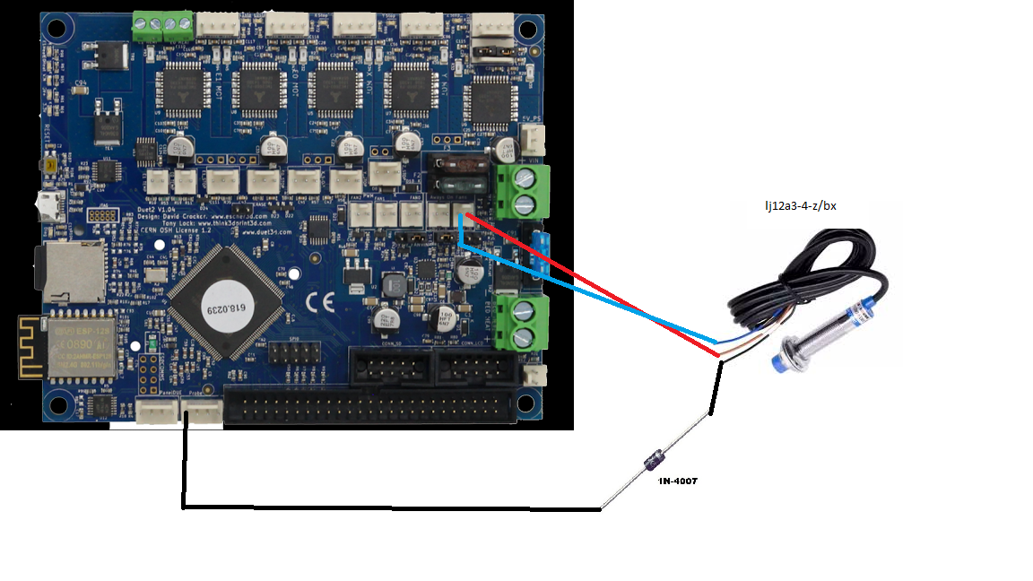
                                I made the following wiring. I used the IN4007 because i dint have anything else on me.

                                The following config changes were done;

                                **; Endstops
                                M574 X1 Y1 U1 S0 ; Set active low and disabled endstops
                                M574 Z1 S2

                                ; Z-Probe
                                M558 P1 I1 H5 F120 T6000
                                M557 X25:0 Y25:0 S20 ; Define mesh grid**

                                and it worked fine.

                                1 Reply Last reply Reply Quote 0
                                • georgepaulundefined
                                  georgepaul
                                  last edited by

                                  Then i tried using theProbe for the U axis and i made this tiny change in the config.g file;

                                  ; Endstops
                                  M574 X1 Y1 Z1 S0 ; Set active low and disabled endstops
                                  M574 U1 S2

                                  And that too worked fine

                                  1 Reply Last reply Reply Quote 0
                                  • georgepaulundefined
                                    georgepaul
                                    last edited by

                                    my doubt is whether this can be done;

                                    ZProbe.png

                                    and if i wanted to connect two probes can one more be connected in the E0 endstop STP pin for the U axis?

                                    1 Reply Last reply Reply Quote 0
                                    • georgepaulundefined
                                      georgepaul
                                      last edited by

                                      i am just making sure i don't fry the board by doing something wrong😇

                                      1 Reply Last reply Reply Quote 0
                                      • First post
                                        Last post
                                      Unless otherwise noted, all forum content is licensed under CC-BY-SA