Connecting multiple Z probes for multiple independent Z axis
-
You have several options. To use the Z probe instead of multiple endstop switches, see https://duet3d.dozuki.com/Wiki/Bed_levelling_using_multiple_independent_Z_motors. To use multiple endstop switches if running RepRapFirmware 2, see https://duet3d.dozuki.com/Guide/Independent+Z+motors+and+endstop+switches/18?lang=en. Or if running RepRapFirmware 3 see https://duet3d.dozuki.com/Wiki/RepRapFirmware_3_overview#Section_M574
-
@dc42 what about putting two probes for each Z?? is that possible??
-
@georgepaul said in Connecting multiple Z probes for multiple independent Z axis:
@dc42 what about putting two probes for each Z?? is that possible??
That doesn't make sense to me. You only need one Z probe. But some people use 2 endstop switches, one for each motor.
-
@dc42 since the extruders are independent, and z axis and x axis will also be independent. we will need two probes right?!
-
@georgepaul said in Connecting multiple Z probes for multiple independent Z axis:
ZideX
I think I see what you mean. That printer design has two independent extruders, each on its own X carriage, and the height of each X carriage is controlled by a separate Z motor. Correct?
In RepRapFirmware 2 you can switch between different types of Z probe using M558, and some types have their own G31 settings. RepRapFirmware 3 will be more versatile. You can already configure multiple Z probes in RRF3 (each with its own type and G31 parameters), all that's missing is a new M-code to switch between them.
With either firmware, you can use the tool change files to select the Z probe you want to use and to switch height maps.
-
what about on the hardware side... where can i put the additional probe pins?
-
@georgepaul said in Connecting multiple Z probes for multiple independent Z axis:
what about on the hardware side... where can i put the additional probe pins?
On Duet 2 you can connect digital-output Z probes to any endstop input as well as to the Z probe connector. On Duet 3 you can connect them to any of the nine IO_x connectors.
-
so even a capacitive probe, working on 12V will not harm the Duet if the signal pin of probe is connected to any endstop STP pin.
-
only on a duet2 v1.04 and up
-
mine says;
M115
FIRMWARE_NAME: RepRapFirmware for Duet 2 WiFi/Ethernet FIRMWARE_VERSION: 2.0(RTOS) ELECTRONICS: Duet WiFi 1.02 or later + DueX5 FIRMWARE_DATE: 2018-06-05b3so I guess it's not compatible!
-
the firmware can not see which hardware revision you have, at those changes are independant of the firmware.
its printed on the pcb
-
ok then im safe... my hardware says Duet2 V1.04... yippie

-
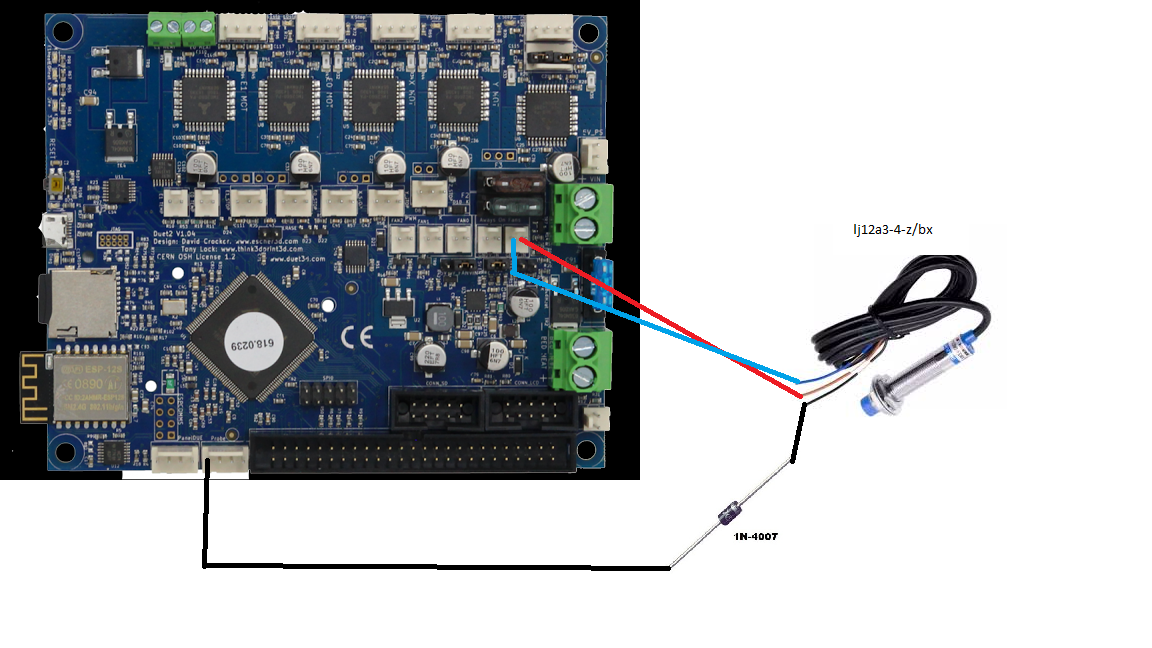
Ok so i did connect a Zprobe and got it working. I made the following changes and it worked for the NPN inductive sensor that I scavenged.

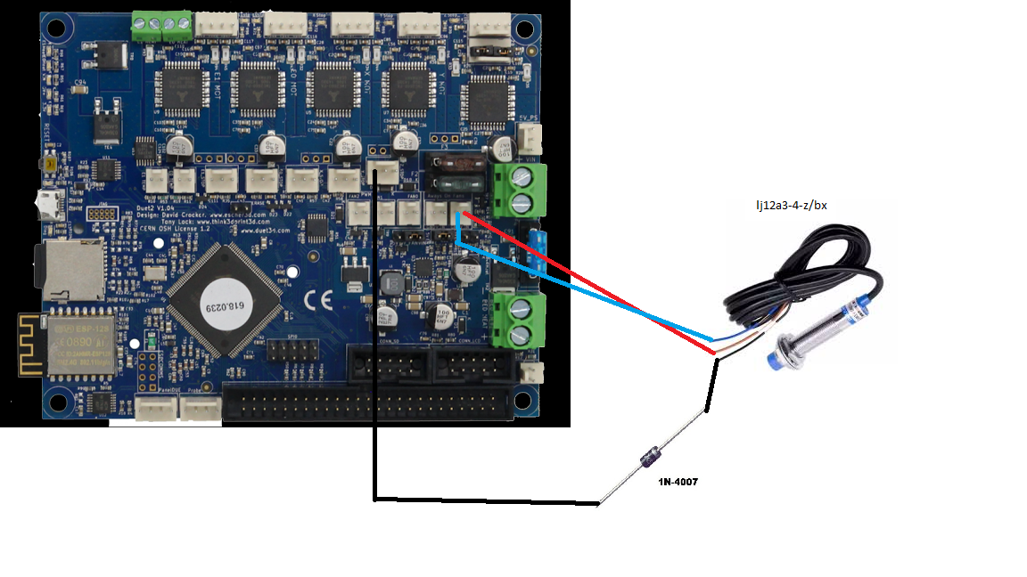
I made the following wiring. I used the IN4007 because i dint have anything else on me.
The following config changes were done;
**; Endstops
M574 X1 Y1 U1 S0 ; Set active low and disabled endstops
M574 Z1 S2; Z-Probe
M558 P1 I1 H5 F120 T6000
M557 X25:0 Y25:0 S20 ; Define mesh grid**and it worked fine.
-
Then i tried using theProbe for the U axis and i made this tiny change in the config.g file;
; Endstops
M574 X1 Y1 Z1 S0 ; Set active low and disabled endstops
M574 U1 S2And that too worked fine
-
my doubt is whether this can be done;

and if i wanted to connect two probes can one more be connected in the E0 endstop STP pin for the U axis?
-
i am just making sure i don't fry the board by doing something wrong
