Wierd lines on the test cube sides
-
Hello,
just rebuilt my Delta printer and trying to calibrate the dimensional accuracy. But when I print test 40x40 test cube, I face some strange lines on the sides (they seem to appear after retraction):
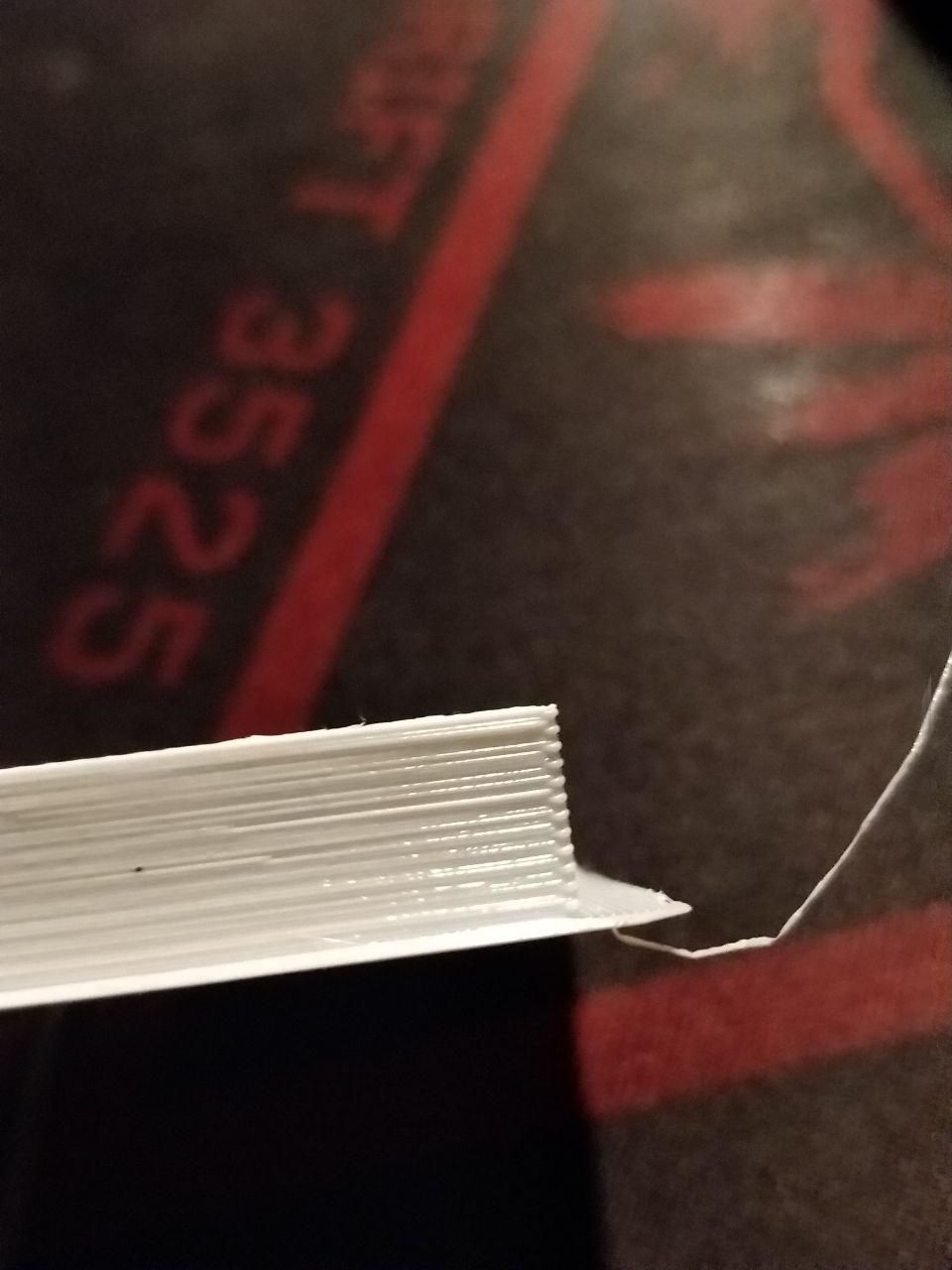
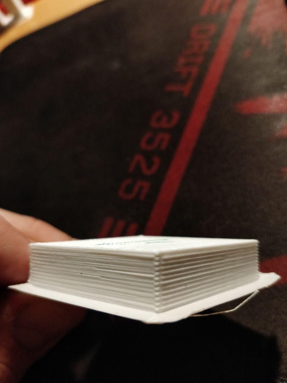
My config.g:
; General preferences
G90                                         ; Send absolute coordinates...
M83                                         ; ...but relative extruder moves
M665 L209.000 R91.5 H205 B100.0 X0 Y0 Z0.000                    ; Set delta radius, diagonal rod length, printable radius and homed height
M666 X0 Y0 Z0             ; Put your endstop adjustments here, or let auto calibration find them

; Network
M586 P0 S1                                  ; Enable HTTP
M586 P1 S0                                  ; Disable FTP
M586 P2 S0                                  ; Disable Telnet

; Drives
M569 P0 S1                                  ; Drive 0 goes forwards
M569 P1 S1                                  ; Drive 1 goes forwards
M569 P2 S1                                  ; Drive 2 goes forwards
M569 P3 S0                                  ; Drive 3 goes backwards
M350 X16 Y16 Z16 E16 I1                     ; Configure microstepping with interpolation
M92 X400.00 Y400.00 Z400.00 E100.00         ; Set steps per mm
M566 X1000.00 Y1000.00 Z1000.00 E12000.00    ; Set maximum instantaneous speed changes (mm/min)
M203 X3000.00 Y3000.00 Z3000.00 E12000.00    ; Set maximum speeds (mm/min) 3000
M201 X250.00 Y250.00 Z250.00 E5000.00            ; Set accelerations (mm/s^2) 250
M906 X1500.00 Y1500.00 Z1500.00 E1500.00 I60 ; Set motor currents (mA) and motor idle factor in per cent
M572 D0 S0.11					; pressure advance
M84 S30                                     ; Set idle timeout

; Axis Limits
M208 Z0 S1                                  ; Set minimum Z

; Endstops
M574 X2 Y2 Z2 S1                               ; Set active high endstops

; Z-Probe
M558 P1 H5 I1 R0.4 F300 T6000                       ; P1, Set Z probe type to unmodulated and the dive height + speeds
G31 Z-0.18 P600              ; Set Z probe trigger value, offset and trigger height
M557 R30 S9                                 ; Define mesh grid

; Heaters
M305 P0 T100000 B4138 R4700                 ; Set thermistor + ADC parameters for heater 0
M143 H0 S120                                ; Set temperature limit for heater 0 to 120C
M305 P1 T100000 B3950 R4700                 ; Set thermistor + ADC parameters for heater 1
M143 H1 S280                                ; Set temperature limit for heater 1 to 280C

; Fans
M106 P0 S0.3 I0 F500 H-1                    ; Set fan 0 value, PWM signal inversion and frequency. Thermostatic control is turned off
M106 P1 S1 I0 F500 H1 T45 X200                   ; Set fan 1 value, PWM signal inversion and frequency. Thermostatic control is turned on

; Tools
M563 P0 D0 H1 F2                               ; Define tool 0
G10 P0 X0 Y0 Z0                             ; Set tool 0 axis offsets
G10 P0 R0 S0                                ; Set initial tool 0 active and standby temperatures to 0C

; Automatic saving after power loss is not enabled

; Custom settings are not configured
M557 R60 S20 ; probe within a radius of 25mm from the centre with a mesh spacing of 20mm
M579 X1.005 Y1.01 ; 1.02
M501
Steps per mm for towers are definetely correct as I use lead screws, extruder just calibrated, also pushes desired length. As an extruder, I use default Anet A8 with Bowden tube connector, so it doesn't have any preload.
Print settings from Simplify3D:
Retraction 4.00mm
Retraction speed 60mm/s
No coasting, no wiping
So, the question is following - what could be the source of those lines? Is something wrong with my extruder settings (speed, jerk, etc), slicer, or hardware itself? I was thinking of switching to Titan but not sure about that.
Best regards, Dmitry
-
It could be mechanical problems in the mechanism. What does the printer look like?
-
@mrehorstdmd I don't have a photo of the final one but it is based on 3060 t slot with metal nuts, angles, and cnc plywood frame about 30mm to keep towers.
I made a test cube with Matter slicer, and the problem seems to be a bit different - fat lines after retract or layer change are still there but a bit shorter.
I also tried to experiment with pressure advance but it doesn't affect at all for my 40cm Bowden
-
A more detailed description of the machine, such as the architecture, size, Z axis construction, etc. would be helpful. This type of problem is often due to less-than-ideal mechanical construction. So far, you haven't provided enough information to allow any sort of diagnosis. Use the same camera that you used to take pictures of the prints to take pictures of the printer and post a few here.
-
@mrehorstdmd please find the pictures below:
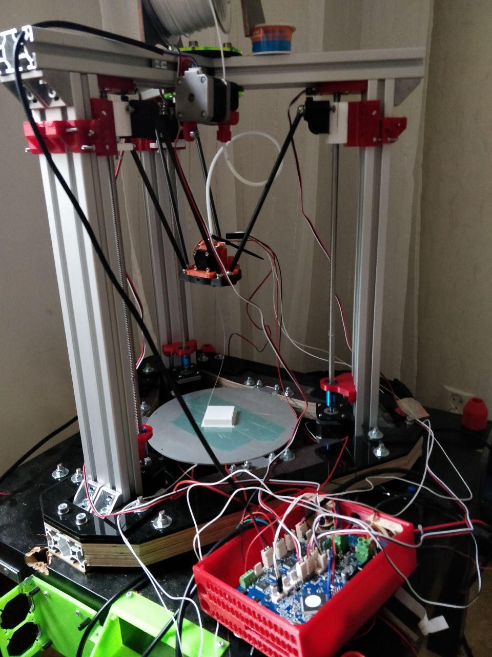
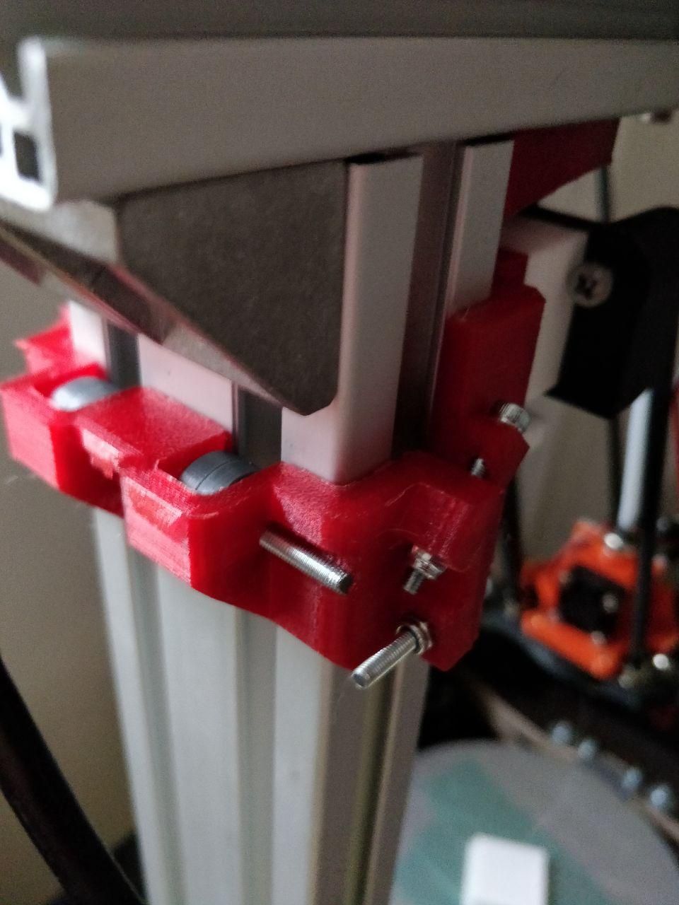
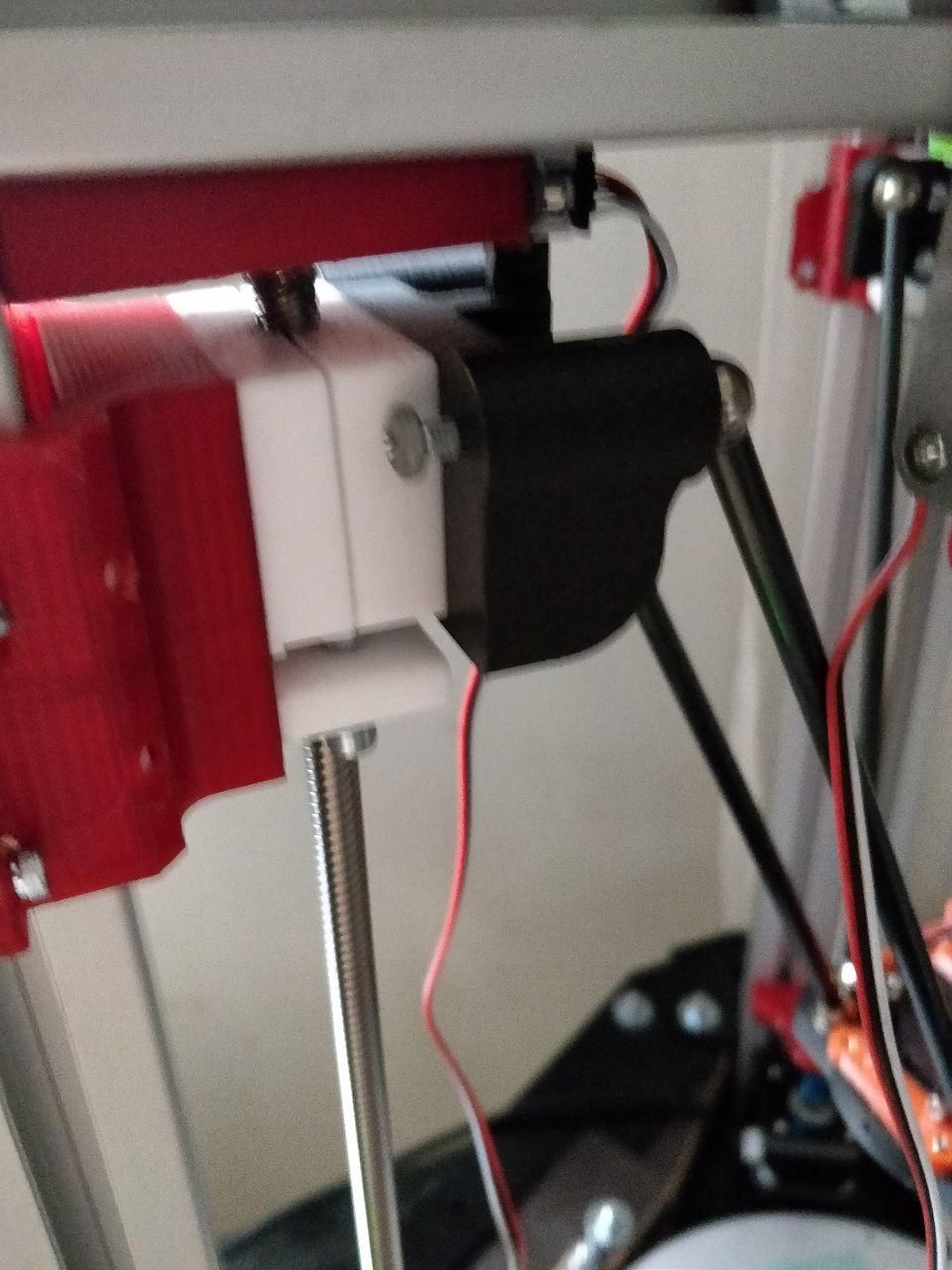
So, just a Delta printer with lead screws and PTFE nuts
-
Here are some possibilities:
-
Your machine has play in the joints (causing backlash), and the slicer has decided to print the perimeters in opposite directions on alternate layers.
-
You have not run heater tuning, so the bed heater is running in bang-bang mode
-
-
@dc42 hello, here is what was printed with Matter Control:
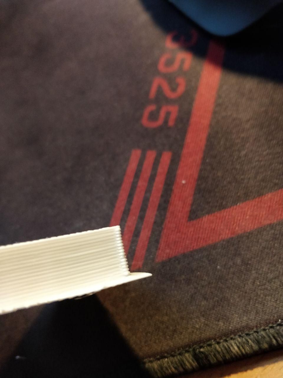
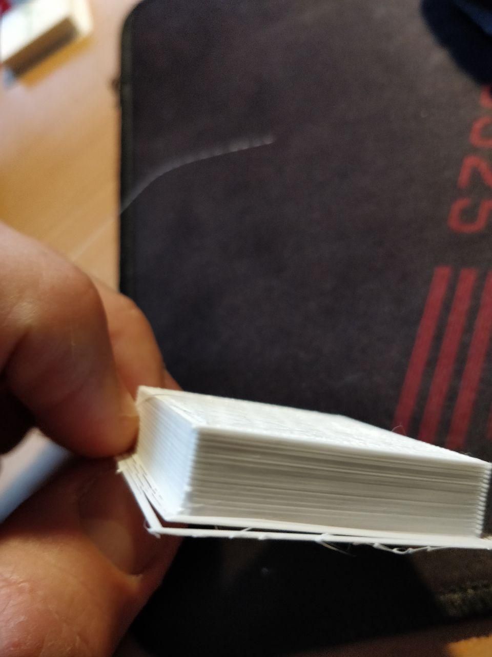
so, walls quality is more or less okay so in the previous example, I suspect, the problem is overextrusion after retract. According to S3D troubleshooting guide, it could be solved by the negative extra restart distance (or I have problems in the extruder - incorrect low speed or jerk).
But, according to Duet docs, extra restart distance is generally bad practice and pressure advance should be used instead.
-
Hi @skayred !
It's hard to see from this angle, but it seems to me that your part is solid?
If so, any (even a very very very slight amount) of over-extrusion can cause effects like this, because there is no other place the excess material can go but off the side of the part (or build up on top and cause the head to eventually collide with it) Plus as DC said maybe each layer is printed in different direction, and there you have it.If the part is indeed solid, then please try to print it not 100% solid, or decrease the extrusion factor a few percent (10% to be sure for the test) and show us the results
-
-
@skayred Probably not ... maybe if you have many perimiters, but unlikely
-
@denke in that case, maybe I am missing some calibration models? Like, I didn't calibrate extrusion width and so on, just started printing test cubes with 3 perimeters at once. If you know what to do first, it would be nice to hear
-
I think you need to fix the backlash in the mechanism before you can calibrate the extruder. Once the layers stack properly on top of each other you can adjust extruder calibration based on line/wall width measurement.
-
@mrehorstdmd hello,
just checked all towers - it slides properly, and I have preloaded PTFE nuts there, so I didnt find any play there.
@dc42 after PID tune, I repeated very first G-code, it seems to be just a little better (no random lines) but overextrusion right at the beginning is still there. Going to experiment with negative restart distance
-
Small update - I just printed 66mm diameter turbine impeller and identified interesting thing - one arm ball at one exact position was going out of magnet's center. I have added some bearing grease, and it prevented the balls from escaping, so impeller was printed without any issues, just really small bowden scars. Still not dimensionally accurate but I think it was the problem
-
Another update - seems to be fixed. What I did:
-
First of all, I have replaced all steppers - old ones were faulty, their shafts were possible to move along, about 3-5mm. New ones don't have these issues and work normally on 2A
-
Replaced 6-factor calibration with 8 factors
-
And finally, adjusted cartesian scale
-
-
@skayred said in Wierd lines on the test cube sides:
- First of all, I have replaced all steppers - old ones were faulty, their shafts were possible to move along, about 3-5mm. New ones don't have these issues and work normally on 2A
Move in the direction of the shaft? This might be by design. All steppers that I've disassembled so far were not constricted to carry any load on the shaft other than rotational. If a stepper motor is new, then it might just have enough friction in the internal parts for it to appear to work, but this will change the longer it runs or depending on the temperature. The coils were centered vertically only by the magnet from my observations.
 But perimeters are printed inside-out, could it be the problem?