Setting tool offset using USB microscope
-
@wilriker has another good way. G10 offsets the tool. And, to @TC's question, G10 Ptool (with no L parameter) becomes "part of the tool" until it is changed. Auto activated when tool is selected, auto-deactivated when different tool is selected.
G92 is not associated with a specific tool. It is temporary (persists to end of current program) and can be turned off via G92 X0Y0Z0.
G54, 55, ... The coordinate settings are persistent across programs, and persistent across power cycles of the machine. The offsets currently in used can be turned on by specifying G54 (or 55 or...) with no arguments.
Note that work coordinate systems CANNOT be "turned off", the machine is ALWAYS in a given work coordinate system (G54 by default). Most people do not realize this, because they are in G54 (default) and G54 has zero offset from machine coordinates. Therefore, they are totally unaware that work coordinate systems even exist.
The one sort-of-exception is G53, which is machine coordinates. However, G53 is not modal; it applies only to the line on which it appears. So, next line, the machine is back in one of the Work Coordinate Systems, which may or may not be offset from machine.
Summary:
-
G10 for offsetting the tool. Auto activate/deactivate as tools are changed.
-
G92, Coordinate offsets are temporary. Often used in combination with gcode subroutines for repetitive parts, like machining a complex pocket in multiple locations on the same part.
-
G54, 55, ... Coordinate offsets are permanent, and activated by G5x with no arguments. Normally for fixtures or jigs.
All three have their uses.
-
-
@wilriker Maybe I have understanding problems but as far as I understood the G10 in combination with a L2 or L20 does not relate to a tool.
"Pnnn Tool number if L=1, coordinate system number if L=2 or L=20"
How does it know which tool is meant?
-
@TC said in Setting tool offset using USB microscope:
@wilriker Maybe I have understanding problems but as far as I understood the G10 in combination with a L2 or L20 does not relate to a tool.
"Pnnn Tool number if L=1, coordinate system number if L=2 or L=20"
How does it know which tool is meant?
Correct, G10 with L2 or L20 is for setting workplace coordinates systems, and nothing to do with tool offsets. It's unfortunate that G10 is used for so many functions.
-
@TC I'm sorry I mixed it up.

@dc42 Would a
G10 L10to set tool offsets relative to current position desirable (makingG10even more complex OTOH)?Manuel
Duet 3 6HC (v0.6) with RPi 4B on a custom Cartesian
with probably always latest firmware/DWC (incl. betas or self-compiled)
My Tool Collection -
The NIST standard defines only L2. Any other L values are "proprietary" extensions of one firmware or another. Including Duet/RepRap's use of "No L parameter at all, with Ptool" to offset a tool.
So... L10 could certainly be used... but... would make Duet/Reprap even further from the NIST standard. Given that G92 accomplishes the exact same thing in an NIST standard way... (and can become "part of the tool" by putting G92 in the pre/post files)... well... you asked DC42 and not me... but you can tell where I'm going with this: I'd say just use G92.
Extract from NIST standard:
3.5.5 Set Coordinate System Data — G10
The RS274/NGC language view of coordinate systems is described in Section 3.2.2.
To set the coordinate values for the origin of a coordinate system, program G10 L2 P … X… Y… Z… A… B… C…, where the P number must evaluate to an integer in the range 1 to 9 (corresponding to G54 to G59.3) and all axis words are optional. The coordinates of the origin of the coordinate system specified by the P number are reset to the coordinate values given (in terms of the absolute coordinate system). Only those coordinates for which an axis word is included on the line will be reset.
It is an error if:
• the P number does not evaluate to an integer in the range 1 to 9.If origin offsets (made by G92 or G92.3) were in effect before G10 is used, they will continue to be in effect afterwards.
The coordinate system whose origin is set by a G10 command may be active or inactive at the time the G10 is executed.
Example: G10 L2 P1 x 3.5 y 17.2 sets the origin of the first coordinate system (the one selected by G54) to a point where X is 3.5 and Y is 17.2 (in absolute coordinates). The Z coordinate of the origin (and the coordinates for any rotational axes) are whatever those coordinates of the origin were before the line was executed.
-
@Danal
Tool offset with limit switches would be great. I was thinking of using a camera and manually doing it, but maybe making a rig with a piezo sensor in X and another piezo sensor in Y both feed into the same module might be a better more automated solution. But is it possible to assign the result to different axis or do you have to get a module for each axis?Let's say I have 1 module with 3 piezo disc. 1 for Z that's used for homing Z. 1 for X and 1 for Y that's not part of the homing process. It's off in the corner away from the bed. I want T0 as referral point so I tell firmware to go to the corner for tool offset calibration to define 0,0 offset for t0. It goes to home Z for the Z offset. Then it proceeds with T1 picks it up, go to the same corner, it should show a different value for x,y that's the difference between it and T0. Then go to homeZ for z offset and does the math as well. Is this possible?
For this to work, the side of the nozzle would have to be the trigger. If there is gunk on it, it would throw it off for obvious reasons.
-
Couple of things:
1) My goal is complete automation. Click one button, no touch, align all tools. I do have camera scripts that involve the human for now... but I intend to make this all work with machine vision. I have samples of that as well. See:
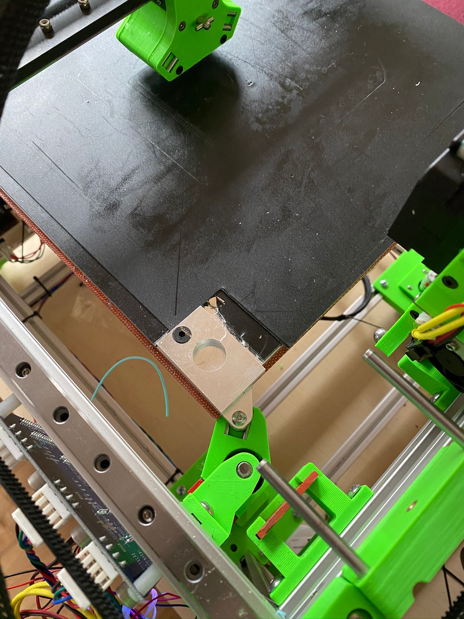
https://github.com/DanalEstes/DuetPython for both human and automated scripts.2) Piezo is one way, but I really don't believe it adds anything that can't be also be done with a simple touchplate. See the scripts https://github.com/DanalEstes/PythonDSF and the touchplate looks like the photo below. Touch the open flat area first to get Z, then put the nozzle 1.5mm down in the hole and touch (several times) to find exact center. As you say, repeat with each tool. Then do the math and set G10 offsets. See: https://github.com/DanalEstes/PythonDSF for examples.
Note this plate is in the corner of the bed... that was a hack just to experiment... final would be off the edge of the bed.
As you mention, plastic is an issue. Nozzle must be heated and wiped.
Delta / Kossel printer fanatic
-
@Danal that is brilliant! Didnt think of using the z piezo probe to do x and y offset. I will look to impliment something like this.
-
@Danal Are you sure you can get the X/Y offset that precise. I am asking because it really depends on where you hit such a nozzle tip.
-
@tekstyle said in Setting tool offset using USB microscope:
@Danal that is brilliant! Didnt think of using the z piezo probe to do x and y offset. I will look to impliment something like this.
There is no piezo involved. It is simple make/break a circuit between the brass nozzle and the touchplate.
-
@TC said in Setting tool offset using USB microscope:
@Danal Are you sure you can get the X/Y offset that precise. I am asking because it really depends on where you hit such a nozzle tip.
XY hits the conical side of the nozzle, not the tip. The exact taper doesn't matter, because the algorithm touches both sides. It only needs to be symmetric with itself. It does not need to be the same as the "next" or "prior" tool.
-
@Danal interesting but that requires the nozzle to be perfectly perpendicular, because otherwise you get an additional offset you dont detect, right?
-
@TC said in Setting tool offset using USB microscope:
@Danal interesting but that requires the nozzle to be perfectly perpendicular, because otherwise you get an additional offset you dont detect, right?
"Perfectly" is pretty strong... you are correct. it does need to be close to 90 to the surface. Eyeball of the whole hot end seems to work.
-
@Danal ok^^ did you already test this procedure? I find it very inspiring.
-
@TC said in Setting tool offset using USB microscope:
@Danal ok^^ did you already test this procedure? I find it very inspiring.
Yes. I've been aligning this way.
Although... I am starved for time... and I've also been testing cameras. So I wouldn't claim any of this is perfected. Both touchplate and camera look promising.
-
@Danal I am working with a USB microscope right now but so far allways have to do manual fine tuning be printing test objects...
-
@TC said in Setting tool offset using USB microscope:
@Danal I am working with a USB microscope right now but so far allways have to do manual fine tuning be printing test objects...
My final target is full automation. I've found that the various microscopes have such a narrow field of view that "starting from scratch" with no offsets (yet), it is often true that if you put T0 over the scope, write down the coordinates (or script capture them), and put T1 in that same position, it won't even be in the field of view.
Therefore, I've switched to the Logitech C270. That specific one because it has a threaded lens held captive by a dot of hot-melt (or similar). It is easy to open up, turn the lens, and get it to close focus.
Anyway, using this camera, and an overlay circle (placed there with openCV), I've found that I can be repeatable to better than the tool-tool repeatability of the printer.
So, yeah, no printing test objects.
C270 image:
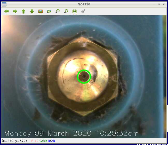


-
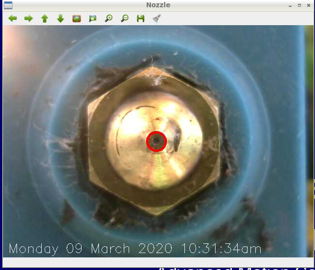
While this looks like the other pic, this is machine vision "finding" the end of the nozzle. This also produces a coordinate (in pixels), and you can see that averaging these over a bunch of reads can get it nailed down:
316.0 240.0
316.0 240.0
315.88 239.88
316.0 239.75
316.0 240.0
316.0 240.0
316.0 240.0I moved the nozzle 0.1mm, and the readings (in pixels) changed to:
312.0 238.0
312.0 238.0appears to be about -4 x -2 pixels, so about 4.472 on the diagonal. Part of the work that needs to be done is figuring out how to "calibrate" movement in Pixels to movement in MM, when this is installed on a bunch of peoples printers, with different focus, and maybe even different cameras.
Delta / Kossel printer fanatic
-
i have a raspberry pi that i used to run octoprint with marlin. i might pick up a c270 to get this to work if i can't use the current raspberry pi camera with a phone macro lens.
-
@tekstyle said in Setting tool offset using USB microscope:
i have a raspberry pi that i used to run octoprint with marlin. i might pick up a c270 to get this to work if i can't use the current raspberry pi camera with a phone macro lens.
My github has a script that interfaces with a Duet, that is it MUST run on a D3/Pi combo connected with SPI cable... and it has another script that will work for (almost) any printer, because that script asks you to type in the coordinates as it steps you through the alignment. Meaning the Pi need not be connected to anything (beyond the camera).
So you can use whichever, if you wish.
On the C270, take it apart and screw the lens in (or was it out?) until it focuses within a few inches. Works great.