Slicing G-Code curves from solid (not mesh) geometry.
-
Not sure about 2D toolpaths, but when using 3D toolpaths most CAM-tools including f360 create a polygon mesh under the hood and uses that for toolpath and rest machining generation. It is computationally so much easier to intersect a polygon mesh with a ray or another mesh than intersecting a BRep model...
To prevent a gazillion G1 segments, f360 allows you to optimize the toolpath with a given precision. I suspect they do some arc fitting and segment joinery there. I suppose they give you the same option when doing additive.
All in all they have everything building block they need now. If rest machining can see where there is still material to remove, the inverse is also true. If they can determine whether the machining tool and holder intersects with the stock and possibly work around that, they can also do so for a printhead. And so on.
What is left is handling the 'wet noodle' (in case of plastic). For that they can either buy the technology, or have a good look at the available codes and re-implement those. -
@DaBit said in Slicing G-Code curves from solid (not mesh) geometry.:
buy the technology
They bought NetFabb a while ago.
-
@DaBit Ah, right... I forgot that most CNC machines want lots of little segments, not true curves...
hmmm.. that's a bummer. Hopefully, at least, we can define the smoothing and tolerance to get those segments to be the exact right lengths for minimum step sizes of extruder and/or X/Y axes, whichever is lower.
@arhi you mean AutoDESK? Lol... they bought meshmixer, they didn't make it. They put the parts they liked into fusion already: see the mesh workspace.
But you're right, I now very much doubt they will generate curves. However, fusion 360 has an API -- perhaps someone could make a plugin to do so.
*not actually a robot
-
@bot said in [Slicing G-Code curves from solid (not mesh) geometry.]
@DaBit Ah, right... I forgot that most CNC machines want lots of little segments, not true curves...
Wrong.. CNC-machines want curves. It is the same as firmware retraction, firmware toolchanges, firmware pressure advance, etcetera. Tell the machine what you want, and let the machine sort it out. And they do a terrific job with blending the segments into a continuous constant-velocity (when CV mode is activated...) path that does not violate acceleration limits. I believe that smoothness would benefit 3D printers too.
I can mill a piece of aluminium with rounded features completely smooth and shiny, and bores quite exactly to size. Most round printed things suffer a lot from faceting and dimensional inaccuracy. Crank up the STL resolution, and the printer is busy processing tens to hundreds of megabytes of very short segment code with a spike of 'infinite' acceleration at every segment joint.
Why not just interpolate the arc and respect the accel limits? If it is a hole, give that firmware a hole to print (or at least a stack of circles) and let it sort it out. At least it can focus on creating the best shape that fits the arc instead of spending all it's cycles on SD-card access, parsing, and inserting insanely short line segments in the queue.
If we could switch to splines, even better

-
@DaBit but, I mean, the g-code is segments, and the machine interpolates curves? I have never used a CNC mill or anything, only a 3D printer of my making...
I agree with the philosophy you laid out there. That's what I want.
-
@bot said in Slicing G-Code curves from solid (not mesh) geometry.:
you mean AutoDESK?
 yes
yesthey bought meshmixer, they didn't make it. They put the parts they liked into fusion already: see the mesh workspace.
Mesh workspace in f360 is rather useless
 but isn't f360 also a purchased product, like meshmixer, netfabb etc etc... I think inventor was their own, dunno what they did with inventor as I see f360 being pushed instead of it
But you're right, I now very much doubt they will generate curves. However, fusion 360 has an API -- perhaps someone could make a plugin to do so.
I hope I'm not but I used a lot of cam tools and must say carving or printing it's always G0/G1... the only places I ever have seen curves
- drilling holes
- forming threads (not cutting but forming threads)
and those are basically hand made macro's so someone manually wrote them for cam tool to just use a block of code ... now I have never used cam on those 12 axes fancy machines that cost more than my house but I kind of doubt fusion360 will be much different here. Let's hope they do, if nothing, to test how these bad boys actually handle curves
-
@bot: A very simple example of curves and CNC: half of an ellipse.
I did use 3D machining, because that is the most close match to 3D printing.The shape with a contour machining operation on it, sort of vase mode, but dumber.
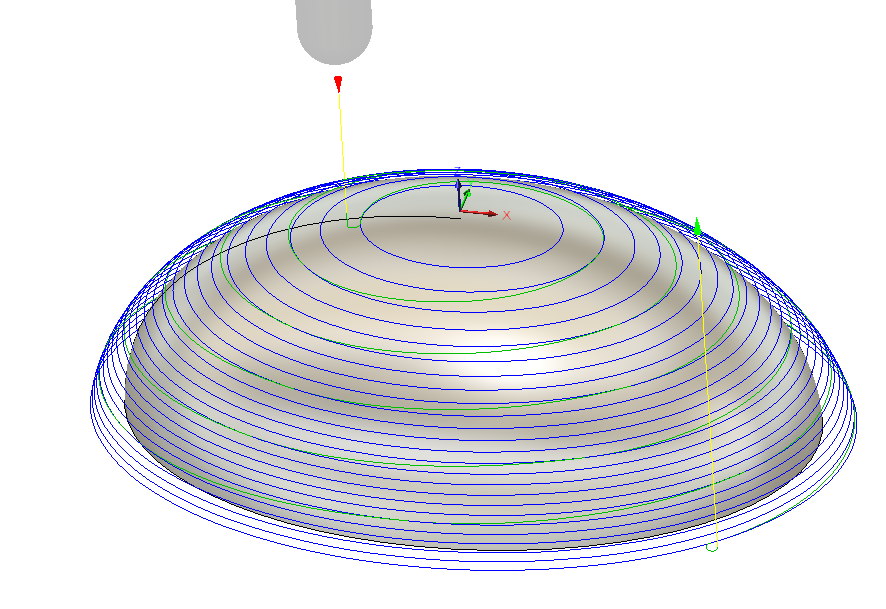
The code, well, part of it:
(8MM BALLNOSE HSS)
N30 S5500 M3
N35 G54
N40 M7
N45 G0 X-11.941 Y-2.03
N50 G43 Z15. H55
N55 G0 Z-0.239
N60 G1 Z-2. F1200.
N65 G3 X-10.745 Y-1.161 I0.418 J0.682
N70 G1 X-10.75 Y-1.14
N75 G2 X-9.389 Y3.788 I5.511 J1.129
N80 X-5.224 Y6.596 I7.157 J-6.122
N85 X3.136 Y7.212 I5.216 J-13.752
N90 X8.884 Y4.382 I-2.11 J-11.539
N95 X10.838 Y0.763 I-4.762 J-4.907
N100 X9.022 Y-4.194 I-5.888 J-0.655
N105 X4.654 Y-6.798 I-7.136 J7.003
N110 X-6.811 Y-5.906 I-4.67 J14.086
N115 X-10.089 Y-2.86 I4.467 J8.094
N120 X-10.751 Y-1.162 I6.671 J3.579
N125 G1 X-10.782 Y-0.985
N130 X-10.815 Y-0.8
N135 X-10.839 Y-0.64 Z-2.001
N140 X-10.862 Y-0.449
N145 X-10.876 Y-0.298 Z-2.002
N150 X-10.891 Y-0.096 Z-2.003
N155 X-10.897 Y0.105 Z-2.004
N160 X-10.895 Y0.234 Z-2.005
N165 X-10.892 Y0.395 Z-2.006
N170 X-10.885 Y0.546 Z-2.008
N175 X-10.872 Y0.731 Z-2.009
N180 X-10.853 Y0.909 Z-2.011
N185 X-10.828 Y1.096 Z-2.013
N190 X-10.796 Y1.292 Z-2.015
N195 X-10.755 Y1.498 Z-2.018
N200 X-10.704 Y1.711 Z-2.021
N205 X-10.651 Y1.912 Z-2.024
N210 X-10.588 Y2.116 Z-2.028
N215 X-10.516 Y2.328 Z-2.031
N220 X-10.404 Y2.615 Z-2.036
N225 X-10.303 Y2.844 Z-2.041
N230 X-10.212 Y3.039 Z-2.045
N235 X-10.066 Y3.318 Z-2.052
N240 X-9.938 Y3.542 Z-2.057
..
..
N645 X14.98 Y1.695 Z-2.983
N650 X15.075 Y1.31 Z-2.988
N655 X15.149 Y0.92 Z-2.991
N660 X15.199 Y0.526 Z-2.995
N665 X15.226 Y0.129 Z-2.997
N670 X15.228 Y-0.269 Z-2.999
N675 X15.206 Y-0.667 Z-3.
N680 X15.163 Y-0.997
N685 G2 X12.255 Y-6.262 I-8.719 J1.381
N690 X6.936 Y-9.396 I-9.608 J10.227
N695 X-4.087 Y-10.177 I-6.934 J19.678
N700 X-11.708 Y-6.796 I2.938 J16.904
N705 X-14.829 Y-2.476 I6.747 J8.161
N710 X-13.393 Y5.01 I7.445 J2.453
N715 X-9.026 Y8.501 I9.438 J-7.331
N720 X-0.475 Y10.551 I8.587 J-16.962
N725 X10.016 Y7.994 I0.754 J-19.714
N730 X14.009 Y4.188 I-6.515 J-10.83
N735 X15.175 Y-0.999 I-6.878 J-4.271
It uses G2 arcs as much as it can. But circles can only be done in the XY/XZ/YZ plane, and that is why you see a whole stretch of G1 short segment code where the cutter ramps down in an arc (most of the 'green lines' between the 'blue lines')
Thus, we won't get rid of the short segment code for these shapes.Another one: text, once again an automatic 3D machining operation (adaptive clearing):
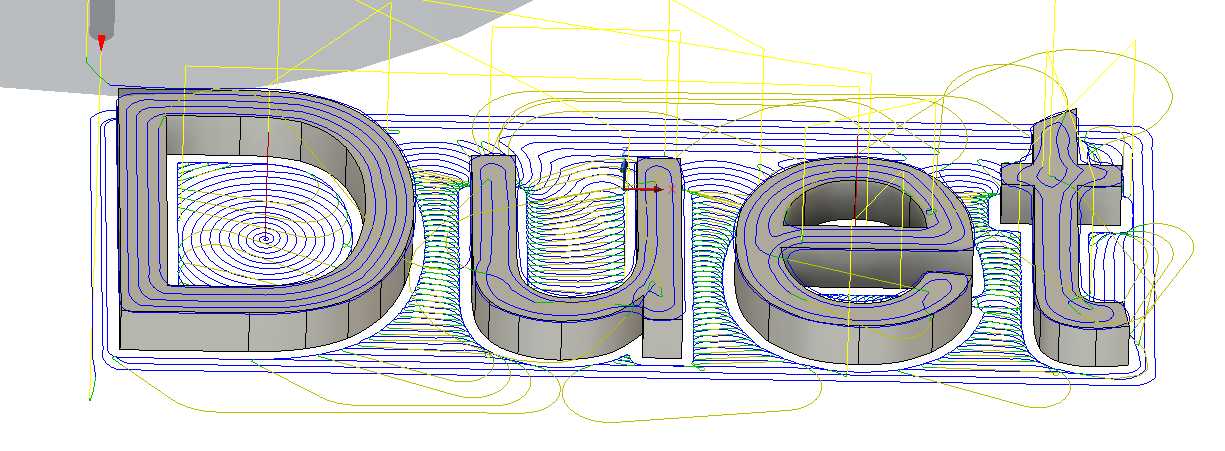
Once again a piece of code:
...
...
N270 G2 X-20.43 Y-7.523 I0.241 J0.81
N275 X-20.779 Y-7.028 I0.175 J0.494
N280 G1 X-20.778 Y-6.626
N285 Y7.108
N290 G2 X-20.024 Y7.76 I0.559 J0.115
N295 X-13.908 Y7.733 I2.674 J-84.969
N300 G3 X-11.691 Y7.553 I2.199 J13.356
N305 G1 X-7.796 Y7.555
N310 X19.822
N315 G2 X20.523 Y6.333 I-0.201 J-0.927
N320 G1 X20.559 Y5.969
N325 X20.561 Y5.615
N330 X20.562 Y4.199
N335 Y-5.651
N340 G2 X20.768 Y-7.149 I-4.593 J-1.394
N345 X20.022 Y-7.562 I-0.63 J0.256
N350 X17.278 Y-7.517 I-1.247 J7.555
N355 X11.16 Y-7.55 I-4.248 J216.39
N360 X7.583 Y-7.534 I-1.755 J7.226
N365 G1 X7.222 Y-7.551
N370 X6.868 Y-7.549
N375 X5.452 Y-7.547
N380 X-1.184 Y-7.543
N385 G2 X-4.139 Y-7.538 I-1.469 J4.827
...
...
As you can see: when it fits the capabilities of the machine a lot of arcs are emitted, allowing the curves to be actually round instead of a faceted approximation. Nothing wrong with a faceted approximation; in the end it all ends up as 'facets' the size of a motor step or encoder count. But at least it reduces G-code size tenfold, and it allows the controller to spend way more CPU cycles on creating nice curves instead of figuring out how to connect the thousand dots that form an arc.
Oh, and BTW, this resembles in no way decent CAM-code. Just synthetic, quick & dirty to give you an idea.
-
@DaBit Duuuude. Thanks for those g-code examples. This is interesting. I was already wondering how some of the crazy splines could be generated -- they can't!
How can a spline be defined, anyway? Would it be nonsensical to attempt to create a g-code spline specification?
-
I must be clairvoyant or something -- Fusion just dropped the update with FFF toolpath creation. See y'all in a few weeks... I've got some exploring to do.
-
I just pulled it down as well. Looks promising at first glance. Now if I could figure out how to generate gcode instead of a 3mf file...
-
How are you guys getting this into your fusion install ?
-
@gtj0 lol... I just generated some toolpaths and they certainly do NOT look promising.
I see no settings for "meshing" or smoothing/tolerance, and the supports are generated based on settings and it seems you can't edit them.
We shall see how they improve it...
-
@jens55 I had to close down fusion, restart it -- then when I restarted it started downloading the update, then when its done you click retsrat fusion 360 (it's in the clock icon at the top right)...
Then it's in the additive pane of the manufacture workspace.
-
Tried that initially but it didn't do an upgrade. Trying again ....
-
Ahh, this time it updated ... maybe I wasn't patient enough. Thanks !
-
I rest my case re my previous opinion about their ability to come up with anything that competes with the current slicers. They have a LONG way to go !
-
@jens55 I'm actually very upset right now how right you were. Damn.
-
Have you guys actually generated a gcode file? If so, how?
-
@gtj0 I did not generate a gcode file. A post-processing script would be required or something..
However, you can "simulate" the toolpath and see the preview of the toolpaths... they use the lowest resolution imagineable in generating the toolpaths. Not even close to approximating curves...
*not actually a robot
-
@gtj0 said in Slicing G-Code curves from solid (not mesh) geometry.:
Have you guys actually generated a gcode file? If so, how?
Tried but wasn't able to ... thought it was just me but glad to hear that it isn't just old age creeping up on me
")