Compiled Firmware with 5bar-Scara / Dual-Arm-Scara
-
@Enpixa , I think your motors run in the wrong direction. Looking at your homing file I see that you home X(left arm) using a move towards negative, but that arm homes at a big angle. Same for Y, but opposite.
Modify your M569s and the homing file. -
@Enpixa I am confused why you set Y285:285, this sets your actuators into the print bed.
-
@Enpixa I will setup my Scara with your parameters at the weekend, please tell me which configuration you have right now und the G-Code of your test "prints".
-
Here are some parts of my configuration file if it helps:
M350 X128 Y128 Z16 E16 I1 ; Configure microstepping with interpolation ; Left homes at 180deg, Right at 0deg M669 K9 X-93:93 Y-205:-205 L2 A10:170:0:360:0:360 C-90:270:-90:270 P134:134 D205.00:205.00:0:0 B180:0 ; Old machine, more sensible limits. Right homing sensor is between arms ; M669 K9 X-54:54 Y-192:-192 L2 A10:170:-90:360:-90:360 C34:251:-71:146 P161.00:162.00 D206.00:208.00 B226.01:152.21 ; 400/360 * 128 * 263 / 16 M92 X2337.777778 Y2337.777778 Z800.00 E420.00 ; Set steps per mm/deg, 128micro ; Axis Limits M208 X-350 Y-350 Z0 S1 ; Set axis minima M208 X350 Y350 Z188.2 S0 ; Set axis maxima M569 P0 S1 ; X Drive 0 M569 P1 S1 ; Y Drive 1 -
@bondus Thank you.
I changed the documentation by some of the items discussed here. After resolving this issue here I want to implement work mode 3 also, and I am looking for a solution how to change work modes automatically.
-
@JoergS5 Work mode 3 is implemented. It is a pretty strange work mode, you will need very specialised arm lengths to get any reasonable work space.
I tried work mode 1 and 4 or my new machine yesterday, they work perfectly fine.
I experimented a few weeks ago with some work mode switching on a toy scara machine run by a Teensy board. I had copy-paste ported our code to run outside RRF.
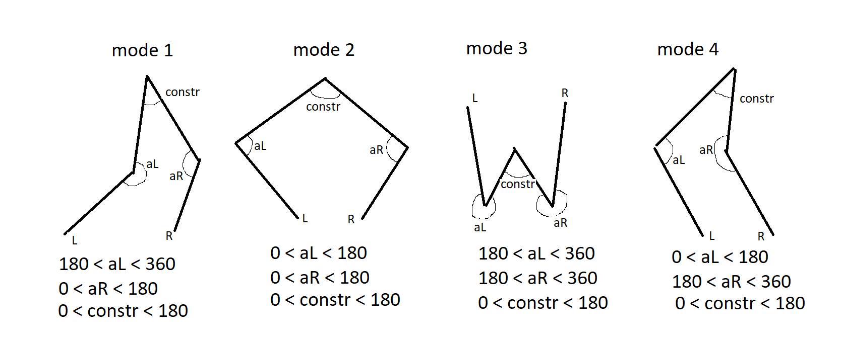
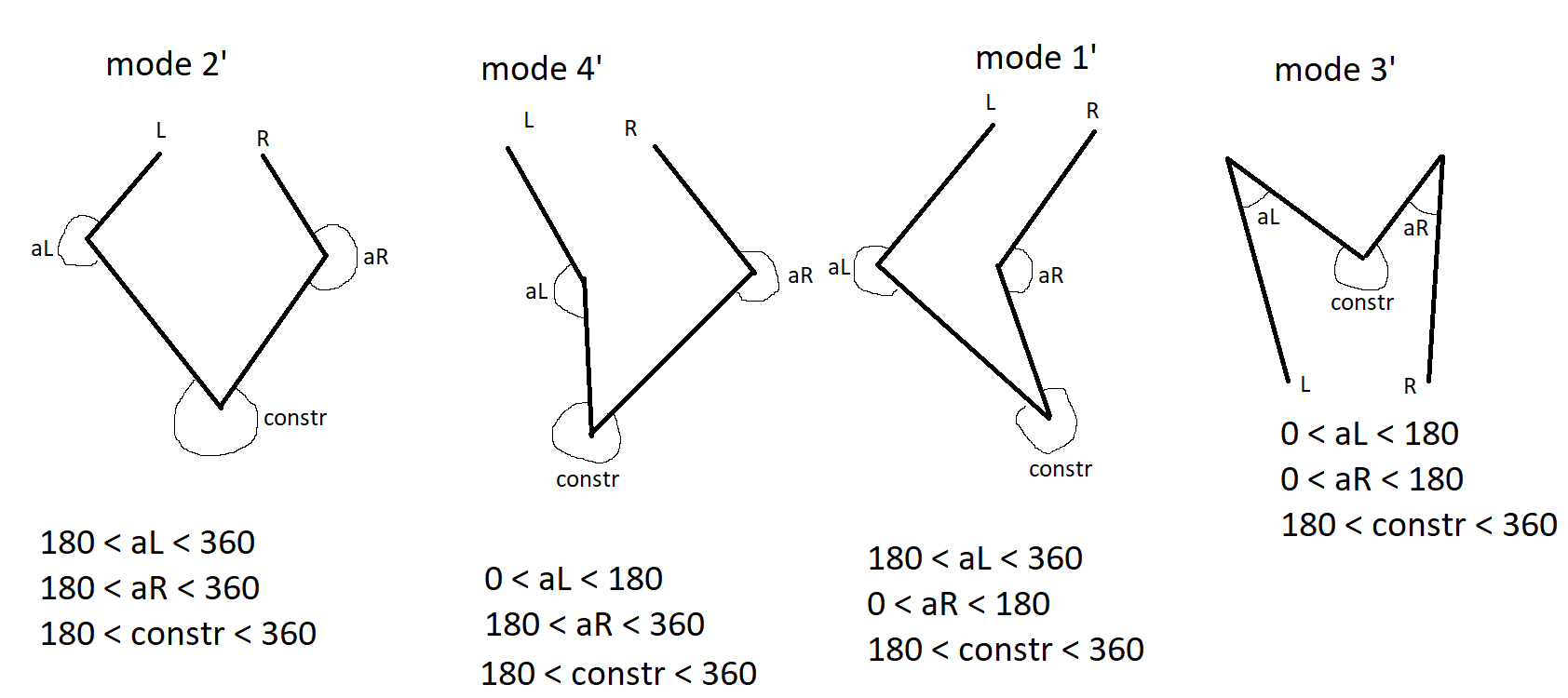
I think that switching can safely be done if done in the right order. Mode 1 can move to mode 2 or 3, mode 2 can move to mode 1 or 4, mode 4 can move to mode 1 or 3. Basic rule is that if you flip one proximal-distal arm joint at a time it will be safe. By flip I mean to change from the range 0-180 deg to 180-360 deg.
The work mode switching order would be 1-2-4-3-1-... , any direction is allowed.Exactly when, how and why to do a switch I'm not sure. Except that it's fun.
If you want to be very brave and flip the actuator joint with a dynamic move that's a very different story
") The firmware does not support the other 4 work modes you have on the other "side".
The firmware does not support the other 4 work modes you have on the other "side".I'll dig up some old pics I made a long time ago ...
-
@bondus I expect work mode 3 not supported because in the source for L:
if (!(workmode == 1 || workmode == 2 || workmode == 4))
{
error = true;
return true;
}so for workmode == 3 will be an error. (My fault, I excluded it, because of missing testing).
For changing work modes, my thoughts are:
every workmode has a safe print area which can be defined for given allowed angles and arm lengths. When changing work mode, a moving path through overlapping areas is a safe path. Moving without printing is safe, but printing while changing workmode is unresolved (the print move must be splitted, either from firmware or in the G-Code). When changing the workmode, all singularity areas must be avoided.My wish to use workmode 3 is:

below = below printbed, above = above, perpendicular = steering bars.
The reason is to save space in x-y dimension.
(To explain: perpendicular is not the proximal arm, but a vertical bar, rigidly connected to the distal arm. The proximal arm is the big plate with a ball bearing inlcuded at the edge. The big plate get a 1:30 gear ratio with the stepper)I want to include your formula and spreadsheet for calculating the stepper setting into the documentation, I'll do that in the next update.
-
@JoergS5 , I made a prototype

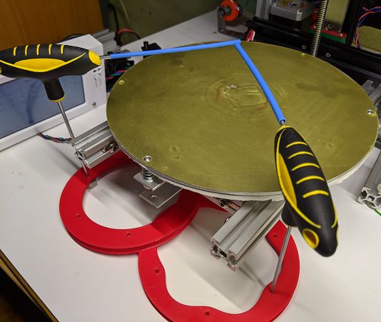
An interesting idea, thinking out of the box.For a work mode change to work today you would have to move the arms as close to the switch point as possible, use a G0 H2 to nudge the arm over to the other side and then reconfigure with an M669. It will lose homing though. We could (ab)use M666 instead, with different parameters. A bit hacky, but it will work for testing.
I'm working a bit with IsContinuousRotationAxis() and related angle logic. As it is today the firmware may select to take the "back route" with the motors, totally ignoring all angle limits. Some machines can do that, others can not.
We are kidnapping @Enpixa's thread.
-
@bondus Nice protoype, and yes, we can start a new thread for "freedom of workmodes". => I'll start a thread for workmode 3, describing my prototype
-
@Enpixa I expect I've found a configuration error: the M574 settings seem to be wrong: according to your setup image and https://duet3d.dozuki.com/Wiki/Gcode#Section_M574_Set_endstop_configuration the left X actuator is a high endstop, the right Y one is a low end endstop.
So the commands should be:
M574 X2 S1...
M574 Y1 S1... (today in your config set to Y2).With printing outside of the print area (angle is outside of the max endstop if Y2 is set), if it behaves like a scara printer, it would make G0 unsegmented moves = curved, which would explain your curved moves. (like in https://forum.duet3d.com/topic/13018/scara-problem)
Could you try this please? And the other possible problem are the steppers which are face down, changing the direction.
-
@Enpixa I found an additonal possible cause:
from https://duet3d.dozuki.com/Wiki/Gcode#Section_G0_G1_Move
RepRapFirmware treats G0 and G1 in the same way 'except as follows:
On SCARA and similar architectures that normally require linear motion to be approximated by short segments, a single continuous non-segmented movement will be used if this can be done without the print head dropping below the current Z height. (My understanding is: for a non-extrusion move it uses an unsegmented move, curved in case of a Scara, if there is no danger to destroy something already printed. In general it would be no problem because the move simply wants to go from A to B, without interest which path it uses - i.e. no pen attached... With your pen you extrude without an extrusion command)
Proposal: try simulating extruding with E and Z parameters (E may be sufficient. Whether you need a dummy E stepper, I don't know).
In case you don't know what is meant by segmentation: a curve is not printed as curve, but split into little segments and printed every segment as a line. The better the hardware, the more segments are used (Duet 3 best, Duet 2 good, depending on the memory available). The Delta/Scara printers have non-linearity of X and Y, so they need segmentation. Otherwise there will be a curve, because the calculation of x-y-relation at the start of the line doesn't fit the situation in the middle or end. For Scara it is even worse: not only the movement path, but also the speed varies (resulting in uneven extrusion if not segmented). Both effects are corrected if the movement is split into small segments.
-
Is 5bar still be developed or worked on?
-
@Phospherus quickly checking the source code, it looks like it's included in 3.4.5 and 3.5beta at least for all supported Duet boards, including Duet2. See also https://forum.duet3d.com/topic/30523/5-bar-scara-on-duet3/14 for a more recent discussion.
-
@oliof Thank you. I went ahead and tried 3.4.5 and have my Morgan style moving and all looks correct. Still need to install bed and hot end.
-
@Phospherus keep us posted, I'd love to see an OG Morgan up and running!
-
@oliof https://youtu.be/9VRnl9GF-Sk Here you go.
-
Is anyone actually using 5-bar kinematics on Duet 2? We're looking to remove the more exotic kinematics from the Duet 2 build to free up flash memory space.
Duet WiFi hardware designer and firmware engineer
Please do not ask me for Duet support via PM or email, use the forum
http://www.escher3d.com, https://miscsolutions.wordpress.com -
This post is deleted! -
@dc42 I like to use Duet2 for my experimental/fun builds, but I can accept to stick with RRF3.4x features.
Although the soon_to_come robotics kinematics would be interesting for me, too.Compiling a custom version on my own is no option, but if there was a customizer tool on top of eclipse, where we could choose the features we'd like and get a tailored RRF version, would be cool.
-
@o_lampe said in Compiled Firmware with 5bar-Scara / Dual-Arm-Scara:
customizer tool on top of eclipse
that's a good idea IMHO, analgoue to the RRF configurator which produced a config.g, this customizer tool would produce the binaries. With additional options like to configure how many drives are needed => optimizing performance vs memory need (additional options: remove or add mesh compensation for those who don't need or need it etc).
You don't need Eclipse, only to run the make exe and Arm toolchain. But a server on which it runs is needed and a responsible person who wants to invest time to do it.