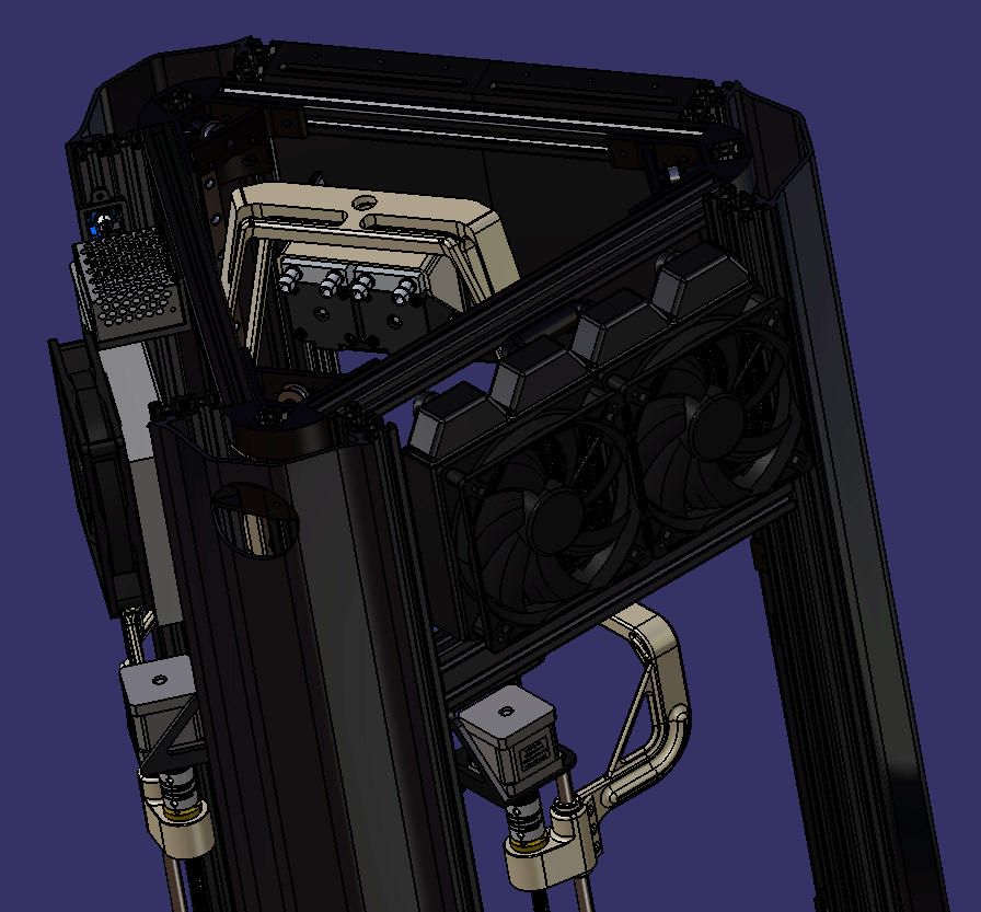
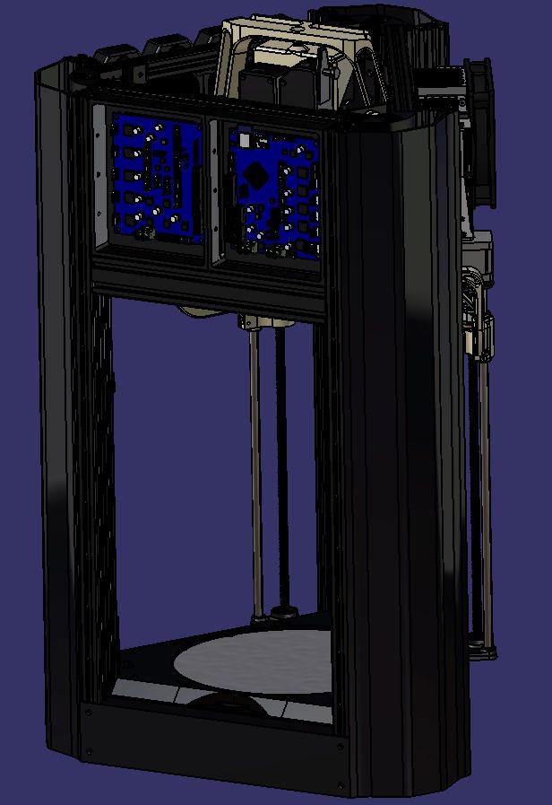
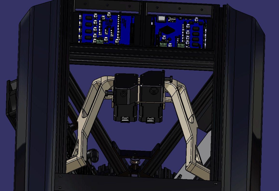
4th axis strange isuues
-
-
-
Which firmware version are you using?
-
When using stall detection, I recommend that before the first homing move you do a very short move (but more than 1 full step) in the opposite direction. This ensures that the motor is not stalled to begin with.
-
I suggest you delete your config-override file and remove M501 from config.g at least until you have a working configuration.
-
-
@T3P3Tony i saw it, and i've take a look also onto the config files updated to him, but i can't find an difference between mine.
that's why i'm asking here, unfortunately searching on forum i had no luck for my problems -
-
my firmware is the version 2.0.4 with the modified .bin files that you'd uploaded with some bug fixed for 4th axis usage (i don't remember in such articles i saw it, it should one of the firsts that discuss about 4th axis
-
now i try to add in homedelta.g an instruction for move it a few mm down before going up, and i give you an result
-
i do it as well, soon the response
for the moments
thank you to everybody -
-
@Eclipssato See https://duet3d.dozuki.com/Wiki/ConfiguringRepRapFirmwareDeltaPrinter#Section_Adding_additional_towers_to_carry_flying_extruders
The main thing I notice from you config.g is:
M665 L268.2:268.2:268.2:600 R116 H290 B115
You have set the U axis to 600mm. But this is not the length of the U axis, It is the distance between the Z and U position! From https://duet3d.dozuki.com/Wiki/ConfiguringRepRapFirmwareDeltaPrinter#Section_Adding_additional_towers_to_carry_flying_extrudersSpecify the rod lengths to each tower individually in the M665 command. Example:
M665 L360:360:360:250 R180.3 H470 B150.0
This specifies that the XYZ towers all have 360mm rods to the effector and there is a 4th tower with a 250mm "rod". This 250mm value is the distance that RRF will maintain between the extruder output and filament entry point on the hot end which is normally at the centre of the effector), so roughly the length of the Bowden tube.
However, there does seem to be an alternative way to get the 4th axis working. Advice from @dc42 is to make U axis very long in M665 (see https://forum.duet3d.com/post/116585 ). @Quadcells also hides the U axis, only unhiding it for homing (same thread, lower down: https://forum.duet3d.com/post/121071 ).
Other people seem to set the U axis to the distance between Z and U, as described in the documentation, eg @Nxt-1 in https://forum.duet3d.com/topic/11183/my-delta-forgot-how-to-delta-4th-axis .
At this point it seems like both methods work, but not a mix of them. And both will rely on homing the U axis correctly, so it knows how to position U relative to Z. It could be that the method described in the documentation only tracks Z, so doesn't move U for X and Y moves. This would be desirable for a camera tracking the Z movement, but not to keep the extruder a set distance from the effector in X, Y and Z. But I don't have a way of testing this.
If you could try both, and report back which works better for you, that would be great.
Ian
-
@droftarts i try, cause at the moment the testing suggested from @dc42 seems had no positive changes
i'll report soon
-
Please update your firmware to 2.05.1.
-
@T3P3Tony said in 4th axis strange isuues:
i think @Nxt-1 had a working delta with a 4th axis of the extruder
Indeed I have, albeit with an endstop at the top of the 4th axis. Below are my config and home file. I sadly do not have time to really help you with debugging at this moment. Hope this can help you anyway

Homedelta.g
; Homing file for Deltex M80 ; Make sure the main PSU in on G4 P500 ; Wait for the voltage to stabalise in range G91 ; use relative positioning G1 H1 X1000 Y1000 Z1000 U1000 F4000 ; move all carriages up 7100mm, stopping at the endstops G1 H2 X-3 Y-3 Z-3 U-3 ; move all carriages down 3mm G1 H1 X6 Y6 Z6 U6 F250 ; move carriages slowly up 6mm, stopping at the endstops G1 Z-5 F2000 ; down a few mm so that we can centre the head G90 ; back to absolute positioning Config.g:
; Configuration file for Deltex ; ===================== GENERAL SETTINGS ===================== M111 S0 ; Debug off M550 PDeltex - V6 ; Machine name and Netbios name M555 P2 ; Repetier Output M575 P1 B57600 S1 ; PanelDue Comm Setup M540 P0xBE:0xEF:0xDE:0xAD:0xFE:0xEA ; MAC Address M552 S1 ; Enable WiFi M586 P1 S0 ; Disable FTP M586 P2 S0 ; Disable Telnet ; ===================== MOVEMENT SETTINGS ==================== G21 ; Set Units to Millimeters G90 ; Set to Absolute Positioning M83 ; Set extruder to relative mode M584 X0 Y1 Z2 U4 E3 ; Assign drives to each motor M569 P0 S0 ; Drive 0 (X) goes backwards M569 P1 S0 ; Drive 1 (Y) goes backwards M569 P2 S0 ; Drive 2 (Z) goes backwards M569 P3 S1 ; Drive 3 (E) goes forwards M569 P4 S0 ; Drive 4 (4th) goes backwards M574 X2 Y2 Z2 U2 S1 ; Endstop configuration (all endstops at high end, active high) M665 L500.000:500.000:500.000:224.000 R236.012 H642.615 B200.0 X0.239 Y-0.157 Z0.000 ; Diagonal rod length, delta radius, printable radius and homed height M669 K3 X0 Y0 ; Location of the 4th axis tower M666 X-0.478 Y4.055 Z-3.576 A0.00 B0.00 ; Endstop adjustments M350 X16 Y16 Z16 E16 U16 I1 ; Set 16x microstepping with interpolation M92 X200 Y200 Z200 U80 E414 ; Set steps/mm M906 X2050 Y2050 Z2050 U900 E750 I60 ; Set motor currents (mA) and increase idle current to 60% M201 X2000 Y2000 Z2000 U2000 E3000 ; Accelerations (mm/s^2) M203 X10000 Y10000 Z10000 U10000 E20000 ; Maximum speeds (mm/min) M566 X400 Y400 Z400 U400 E3600 P0 ; Maximum instant speed changes (mm/min) M591 D0 P5 C4 R40:120 E3.0 S1 ; Duet3D laser sensor for extruder drive 0, connected to endstop input 4 (E1), tolerance 40 to 120%, 3mm comparison length, enabled ; ================ HEATING AND COOLING SETTINGS ============== ; Thermistors M305 S"Bed" P0 B3950 ; Bed temperature sensor parameters M305 S"Hotend" P1 B4725 C7.060000e-8 ; Hotend temperature sensor parameters M305 S"Water" P2 X2 T10000 B3950 ; Water temperature sensor parameters M570 S180 T15 S4320 ; Configure heater fault detection, allow a fault to persist for 180 seconds (+/- 15°). Cancel the print if the fault is not cleared after 4320 minutes (3 days). M307 H0 A408.0 C897.0 D2.1 S1.00 V24.2 B0 ; Set bed heating process parameters and use PID at 10Hz M307 H1 A571.9 C293.5 D5.4 S1.00 V24.2 B0 ; Set hotend heating process parameters and use PID M143 H0 S200 ; Set maximum bed temperature to 200 ; Fans M106 P0 I0 H-1 ; disable thermostatic mode for fan 0 (part cooling) M106 P1 S255 T45 H1 ; enable thermostatic mode for fan 1 (hotend) ; ====================== TOOL SETTINGS ======================= M563 P0 D0 H1 S"Hotend" ; Define hotend tool G10 P0 S0 R0 ; Set tool 0 operating and standby temperatures M207 S0 R0 F3000 T1200 Z0 ; Set default retraction settings M563 P1 S"Water" H2 ; Set up an extra tool to display heater temperature ; =================== CALIBRATION SETTINGS =================== M558 P8 F1200 H3 R0.4 T10000 A10 S0.04 ; Z Probe type 8, input 0, invert no, dive height 3.0mm, probe speed 1200mm/min, travel speed 10000mm/min, recovery time 0.40 sec, heaters normal, max taps 5, max diff 0.04 G31 X0 Y0 Z-0.15 P100 ; Set the zprobe height and threshold (more negative values translate into a higher nozzle) M557 R200 P21 ; Define probing mesh grid M912 P0 S-12.35 ; Set temperature offset for MCU T0 ; Select hot end M501 ; Load settings from config-override.g -
@Nxt-1 No problem at all. thank'you for your configuration, i'll try to match with mine and find the problem
@dc42 done to 2.05.1and installed an simple microswitch as limit
seem better. no problem with zero and it follow the z axes now. (i dont know why the limit switch didnt work on duex, i had to install on duet port, anyway, minor issue)
now i have to define an quote to mantain with my z axis. i found that i have not enough lenght on the thread and i cant use some more long than that.is it possible to said to the printer to take all 4 zero in one position and then move only z axis down 10mm and mantain that distance to the u axes?
keep experimenting -
-
some update...the printer seem to be working correctly now! many thanks to all!
now,
i have to fix the last problem. i need to mantain the 4th axis 30mm over the current position after the homing, cause i have insufficient lenght as i mentioned before. and i have no possibility to move it up.is it possible to do it via firmware?
at the moment i've made in that way and it seems to work properly.
any suggestion?; homedelta.g ; called to home all towers on a delta printer ; ; generated by RepRapFirmware Configuration Tool v2.1.8 on Sun Jan 19 2020 19:28:23 GMT+0100 (Ora standard dell’Europa centrale) G91 ; relative positioning ;*** Slow homing has been configured. Change F300 to F3000 below when your configuration is working G1 H1 X325 Y325 Z325 U325 F1000 ; move all towers to the high end stopping at the endstops (first pass) G1 H2 X-3 Y-3 Z-3 F600 ; go down a few mm ;*** Slow homing has been configured. Change F300 to F360 below when your configuration is working G1 H1 X10 Y10 Z10 F200 ; move all towers up once more (second pass) G1 Z-30 F1000 ; move down a few mm so that the nozzle can be centred G1 H2 U30 F1000 ; 4th tower clearance of 30mm G90 ; absolute positioning G1 X0 Y0 F600 ; move X+Y to the centre -
@Eclipssato said in 4th axis strange isuues:
i have to fix the last problem. i need to mantain the 4th axis 30mm over the current position after the homing, cause i have insufficient lenght as i mentioned before. and i have no possibility to move it up.
is it possible to do it via firmware?The firmware assumes that when all axes have been homed, the U carriage is at the correct distance from the effector, and it will maintain that distance.
What I think you are saying is that you have insufficient height on the U axis to maintain sufficient distance. The following might work (I haven't tested it). Home the printer as normal. Suppose you then want to move the U axis to be 15mm higher than it is (but it can't move up any further). Use a G1 Z command to move down at least 15mm. Un-hide the U axis if it is hidden, and read off the U coordinate in DWC. Now send a G92 Uxx command where xx is 15mm lower than that coordinate (to make the firmware think the U carriage is 15mm lower than it really is). Then hide the U axis again. Then make a small movement. You may find that the U carriage rises 15mm to "correct" the U coordinate error that you introduced using the G92 command.
Of course, if you then try to move within 15mm of the maximum height, the U carriage will crash into the stop.
So the only real solutions are to increase the range of the U carriage, or move the X, Y and Z endstop switches down by the appropriate amount.


