For anyone still using endstop switches...
-
I recently installed opto endstops in my corexy printer and ran some tests of their precision.
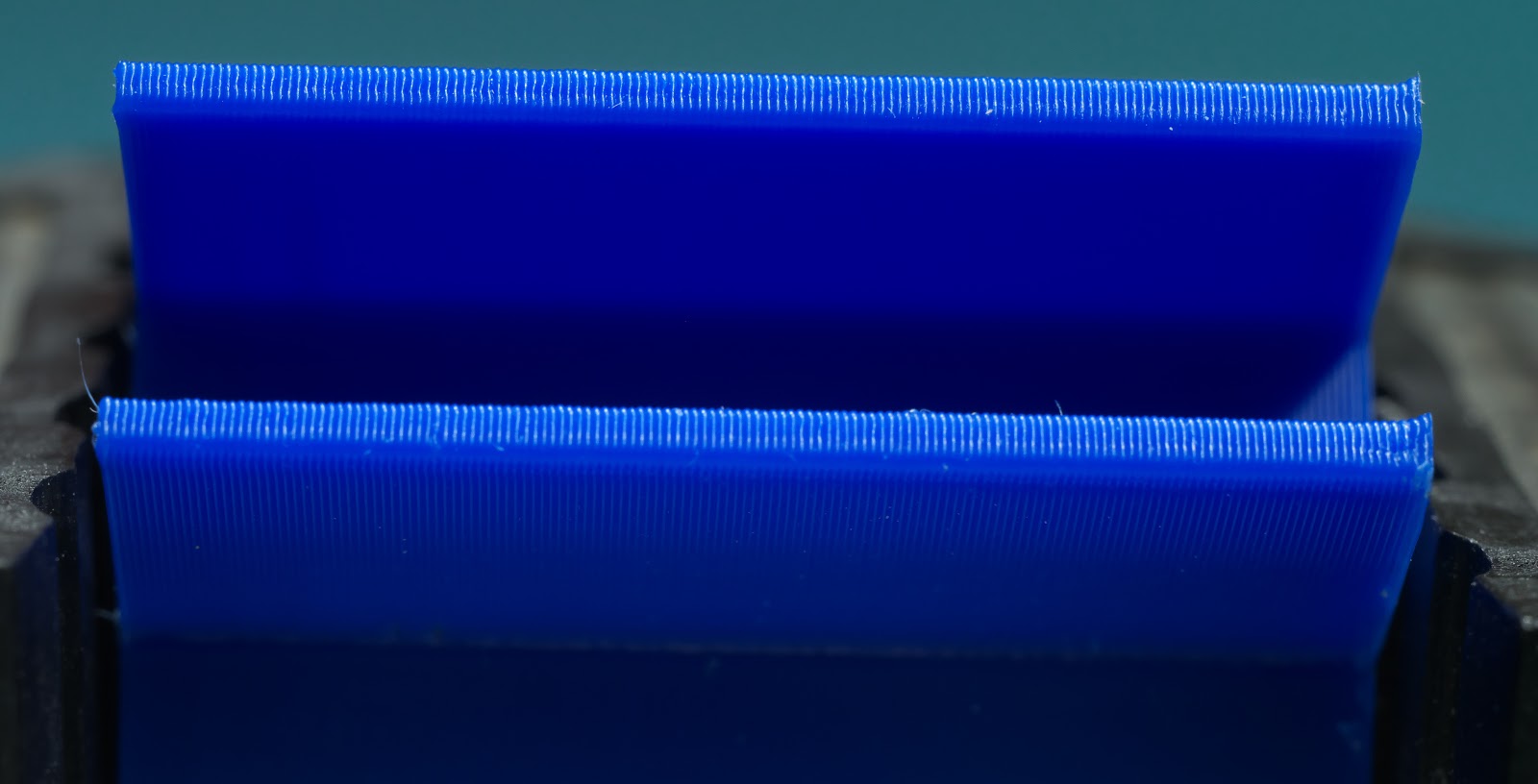
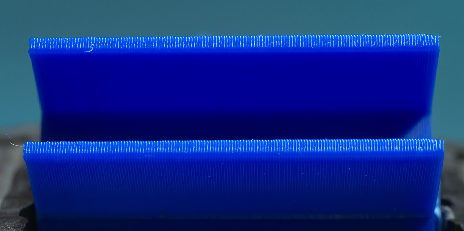
In the X and Y axes I ran two identical prints with the first homing normally at the start of the print and the second rehoming X and Y after each layer change. The result is that the prints are barely distinguishable under high magnification and are essentially identical without magnification, indicating that the precision of the optical endstops is very high. Here are two photos of the prints that contain the largest visible difference between them:
Why would anyone want to home a print at every layer change? MarkForged printers use that feature to automatically detect and stop layer-shifted prints. If you are printing expensive material such as PEEK, PEKK, Ultem, etc., you want the print to stop pretty quickly if there's a problem like layer shifting. I'm thinking about how to program a macro that will detect layer shifting in printers running Duet controllers.
I also tested the Z axis opto endstop. I mounted a digital gauge on the printer's frame with the probe contacting the bed, then homed the machine and zeroed the gauge. I moved the bed down random amounts and rehomed 10 times to see if the bed would return to the same position as indicated by the gauge. 8 out of 10 times it went to 0.00 mm and the other 2 times it went to 0.01 mm. The Z axis in my printer is configured for 16:1 ustepping, interpolation on, and 800 steps/mm.
Video here: Z axis homing precision test
The typical way to adjust the Z=0 position is to use a screw to bump a microswitch. The problem with that is when you're zeroing the Z axis you need to be able to make very small adjustments to the home position of the bed/extruder. If you use an M4x0.7 screw, one turn of the screw moves the home position by 700 um- that's more than 3 full 200 um print layers. If you need to move the home position 30 um, that's 1/23 of a turn - not too easy to do without overshooting.
I designed a differential screw adjuster to go with the optical endstop in the Z axis. It uses a M5x0.8 screw with the end 20 mm or so turned down to 4 mm and rethreaded with a M4x0.7 mm die. The result is an adjuster that moves the home position of the bed by 100 um for each full turn of the adjuster, making it very easy to make small adjustments.

While I was running the other tests I checked the adjuster, too. The result- about 100 um per turn of the adjuster, as expected.
Video: Differential screw Z=0 adjuster test
One of the best things about opto endstops is the cost. 3 for $10. They work fine with the 3.3V that the Duet supplies. They also don't seem to mind the 50C temperature inside my printer's enclosure when I'm printing ABS. These endstops have LEDs that light up when they are triggered, making the Z=0 position adjustment easy because you don't have to check the control panel of the printer - just turn the adjuster until the light comes on.
More here:
https://drmrehorst.blogspot.com/2020/03/a-new-z-axis-optical-endstop-design-for.htmlhttps://drmrehorst.blogspot.com/2020/03/testing-ummds-xy-optical-endstops.html
https://drmrehorst.blogspot.com/2020/03/testing-ummds-new-z-axis-optical.html
-
Repeatability of the endstops is rather high, even for high quality spring microswithes, let alone good optical endstops. Now, I personally never printer PEEK, PEKK.. (I machined them few times) but considering price of that filament why would anyone use open loop driver for any axes?!?! Conversion to high precision silent servo's or closed loop steppers cost less than one failed print with those filaments.
-
Hi,
You can also "adjust" your Z end stop in your homing code.
Let's say your Z end stop switch position is not perfect and leaves you 0.7mm away from the desired location after homing. You can add a G92 Z0.7 to the end of your homing code. Now Z=0 will be spot on.
Frederick
-
@arhi Yeah, I think everyone knew precision was "rather high", but how high is that, exactly?. Now I have numbers for optical endstops. Is the precision of optical endstops necessary in a 3D printer? I don't know. I guess it depends on what you're trying to do. But knowing that they are as good as they are may lead to some interesting possibilities, like the shifted print detection used in the MarkForged machines. What if you were using a cutting tool, a microscope, a tattoo needle, or pick and place head instead of a plastic extruder?
I'm sorry I didn't run the same tests with the microswitches I had before the opto endstops. I'm probably too lazy to reinstall the snap switches and run the tests again. We'll see.
@fcwilt Yes, you can do that, but compare that to twisting a screw that has an LED to indicate when the switch is closed. I'm an idiot and I'd be thinking "should I add 0.7 mm or -0.7 mm?", and I'm bound to get it wrong a few times. I've been using adjuster screws for so long that for me, physically moving the endstop and/or twisting a screw is less likely to end in a crash.
I can see a big advantage to the "soft" approach. If you have an adjustable endstop trigger, there is always the possibility of it getting moved. I've learned from experience at the makerspace that if you put a thumbwheel on a screw, someone is going to turn it, especially if you tell them not to. The mechanical design of an adjuster isn't trivial, especially if it includes plastic parts that may flex while making adjustments. A fixed endstop and fixed trigger for it combined with an offset in the config or homing file is about as stable as things can get. In a mechanically stable printer, the offset should never, ever need adjustment. And of course, you can set a 2 um offset as easily as a 20 mm offset, so you don't need things like differential screws.
I'll give that approach a try and see if I can work that way. I do like things to be stable...
-
@mrehorstdmd said in For anyone still using endstop switches...:
especially if you tell them not to
Amen, brother!
-
@mrehorstdmd said in For anyone still using endstop switches...:
@fcwilt Yes, you can do that, but compare that to twisting a screw that has an LED to indicate when the switch is closed. I'm an idiot and I'd be thinking "should I add 0.7 mm or -0.7 mm?", and I'm bound to get it wrong a few times. I've been using adjuster screws for so long that for me, physically moving the endstop and/or twisting a screw is less likely to end in a crash.
Well since it's common to home to Z min the goal is to get the nozzle in the desired relation to the bed (touching or a slight gap) when Z=0.
So you mount the endstop switch so homing ends at some Z>0 position, then the G92 Z value will always be positive.
Frederick
-
@mrehorstdmd said in For anyone still using endstop switches...:
In a mechanically stable printer, the offset should never, ever need adjustment.
I can vouch for that, i have an extremely stable Z axis with all milled components with a fixed build plate, the last time i leveled the bed was a year ago when i built it, and the last time i set the Z offset on the limit switch was 3 months ago.
The bed is still dead level.I´d like to see your test of rehoming every layer be done with sensorless homing. I bet there would be quite some spatter.
Also, I don´t understand that Markforged sacrifices so much time for checking for lost steps, instead of investing 300$ more in some proper servomotors.By the way, your limit switch with the M5/M4 thread is quite clever. I will probably take that over soon. Well done

-
Yah, my Prusa 3 with Pinda probe, I set Z once when I built it about 8 months ago. Haven't touched it since. Prints almost every day.
Delta / Kossel printer fanatic
-
I don't have much praise for my Up Mini 2, but indeed, I set the zero for Z when it was new and only time I had to change it was when I changed the whole X carriage and bed assembly (or Y carriage in a normal world). I even just copied the value over to my Duet 2 Maestro config and adjusted it for the thickness of the two different bed materials provided which Tiertime does behind the scenes. Never missed a beat (because of endstops at least..)
-
@Danal said in For anyone still using endstop switches...:
Yah, my Prusa 3 with Pinda probe, I set Z once when I built it about 8 months ago. Haven't touched it since. Prints almost every day.
Using the Pinda probe is cheating! We´re talking about true level here
-
@mrehorstdmd Your 0.7/0.8 idea is really great and I will use it to calibrate the print bed (the three points below it) and to finetune an axis tilt.
-
My endstop switches are better than your optical switches neener neener neener!!

-
@mrehorstdmd said in For anyone still using endstop switches...:
@arhi Yeah, I think everyone knew precision was "rather high", but how high is that, exactly?.
There were actually a lot of numbers out there, IIRC Tom S. made a video comparing whole bunch of them measuring repeatability etc...
I did a test of some endstops I was designing 11 years ago, I don't have that data anymore (maybe available in some bitsfrombytes forum archive) but when I first saw the numbers offered by the bltouch that was very close to what I remember having
Thomas 12 sensors test:
https://youtu.be/il9bNWn66BYrwg42985 bunch of switches test:
https://youtu.be/BLzCeH1hS9g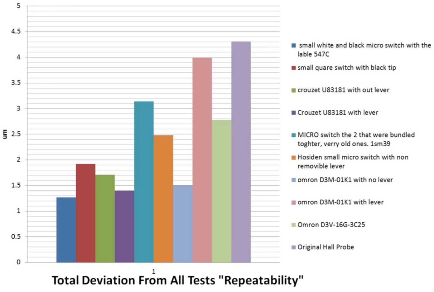
There are many other but these two I remember by name so were easy to find
")
-
So 1 on the axis labled 'um' would be .001mm? "Small square switch with black tip" is under .002?
Where have I slipped a decimal? I ask because Metrol charges a bunch for "high precision" switches with .005mm or .003mm repeatability.
-
@Danal said in For anyone still using endstop switches...:
So 1 on the axis labled 'um' would be .001mm?
yup
Where have I slipped a decimal? I ask because Metrol charges a bunch for "high precision" switches with .005mm or .003mm repeatability.
You might want to contact guy that made the video.
Mine experience is in line with bltouch graph, I measured around 0.02-0.05mm on the range of microswitches I have (nothing close to 0.003 you mentioned or 0.0015 you can see on rwg graph), and when I put that microswitch on a lever that is turned by the RC servo the repeatability drops to unusable 0.1-0.5mm ... I was still using that setup as repeatability while not moving the servo was still below 0.1 so it was ok for 3 point probe (drop the servo, probe 3 points, get the switch out of the way)
I did on the other hand get much better results than bltouch show for optical sensor. They state 0.01, I was geting easily order of magnitude better results but with rather expensive (at the time) optocouplers and hand machined brass mechanics... but even cheap optocoupler with bear can cutout was better than 0.01
... on the other side, inductive, I think I still have over 20 different inductive sensors here, maybe even more, I never managed to get even 0.2mm 
btw all my tests were in range 10C to 40C ... I assume he can get 0.0015 easily if he has constant temperature during the test
-
btw, the "accuracy" chart is maybe more interesting than deviation
and also "all the data": https://open-source-energy.org/rwg42985/russ/Projects/3D printer/micro switch Z probe Data/probe testibg final corect values .xlsx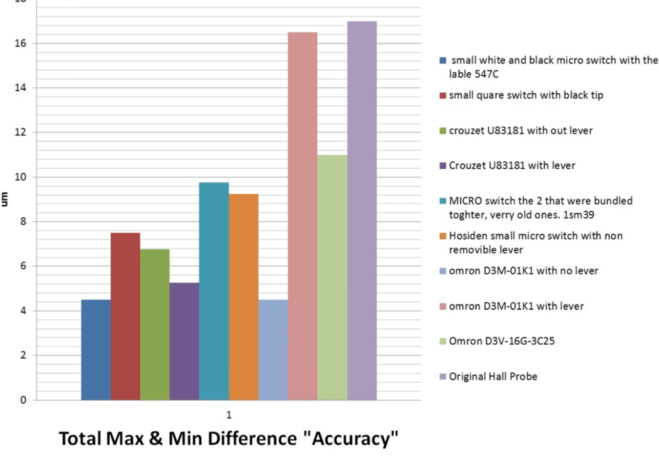
-
@arhi The graphics are interesting, but I have a problem with these statistics because I can not find most of the endstops to buy (only Omron D3M).
And optical endstops: the datasheet don't have any concrete statements, only some curves like +-0.5 mm accuracy (e.g. the ubiquitous TCST2103 based ones). Measuring depends on measured current, so combining it with a good analog-digital currency measurer (like ADS1115) and voltage reference (like LM4040) should improve achievable precision. ADS1115 transmits data with I2C, it should be possible to connect to Duet and decide by threshold.
-
@JoergS5 said in For anyone still using endstop switches...:
@arhi The graphics are interesting, but I have a problem with these statistics because I can not find most of the endstops to buy (only Omron D3M).
That is just some "available data", and there's more if you look for it. Now, I personally would never trust this data for exactly the same reason. I would get the microswitches I can easily source locally, or from some reputable source that can provide the same parts in the future (digikey, farnell, mouser...) and do the test myself.
BTW, you are aware that you can increase the precision of the microswitch by 2 orders of magnitude easy by using a longer lever? Similar with opto too.
And optical endstops: the datasheet don't have any concrete statements, only some curves like +-0.5 mm accuracy (e.g. the ubiquitous TCST2103 based ones). Measuring depends on measured current, so combining it with a good analog-digital currency measurer (like ADS1115) and voltage reference (like LM4040) should improve achievable precision. ADS1115 transmits data with I2C, it should be possible to connect to Duet and decide by threshold.
TBH, if you enclose the opto in a "dark box" and do the proper "slide in fast, retract slow" homing procedure, a simple comparator will do the trick and it will be super repeatable if you don't have huge temp swing and if your Vcc is relatively stable. It will be IMO (have not tested) more precise then measuring analog output and hitting th 'cause in this case you will have both the Vcc regulator and the comparator on the same board at the same temperature so any temp swing will affect them all together :).
Now, as I said, nitpicking with them is IMO huge waste of time. I used optical ones 'cause I was afraid microswitches will fail due to moving parts. But microswitches last decades in lot heavier applications than ours so that was a wrong assumption by me. I was planing for my next machine to use piezo's for positioning but I gave up and a simple printed lever and el-cheapo microswitch can get you where none of the expensive endstops will get you. Just a super simple math, the longer the arm the more precise the movement. It is not very compact for the touch probe, but for XYZ limit switches it's plenty small
-
@arhi Thanks for your additional information. I agree that one has to test himself. Even a tested endstop could be changed in production and has other properties now. The precision data in the datasheet are very fuzzy in addition.
The reason why I prefer optical endstop is that I need endstops which can be "traveled through", from the other side also (a round wheel for 360 degree turns). As far as I see, only magnet based and optical endstops can achieve this. Mechanical ones could be tilted away after measuring, but this will change the reference due to imperfect hinges, and needs an additonal actuator. My needed endstops not only need repeated precision, but also absolute precision to measure the degrees of the wheel (=> optical encoder being better for this requirement, I know...).
The Omron D3M endstops without lever have an overtravel of only 0.4 mm, which limits the speed the endstop can be approached. This may be another aspect to take into account when comparing endstop types. Optical endstops will have a longer overtravel.
-
@JoergS5 said in For anyone still using endstop switches...:
The precision data in the datasheet are very fuzzy in addition.
They are not manufactured to be precise, that's why that data is "fuzzy". The important data is "bouncing", number of open/close cicles during lifetime etc. On some the "pressure force required".. but "precision" is normally not something switch manufacturers care about

The reason why I prefer optical endstop is that I need endstops which can be "traveled through", from the other side also (a round wheel for 360 degree turns). As far as I see, only magnet based and optical endstops can achieve this.
Not sure I follow, all cnc machines use mechanical microswitches that can be "traveled trough" ?!
Something like these (10A 250V IP65):
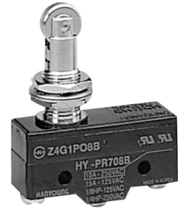
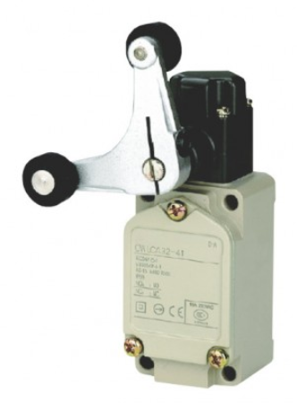
But even when you look at professional endstops, they are IP65, they can survive vibrations, many switches, high forces etc etc, but no "precision" is set there as you don't use switches to home, you use camera or special touch probe.
The Omron D3M endstops without lever have an overtravel of only 0.4 mm, which limits the speed the endstop can be approached. This may be another aspect to take into account when comparing endstop types. Optical endstops will have a longer overtravel.
Well what I'm suggesting is something like the second image I put here. The length of the arm defines precision. Shorter the arm side towards bed, better the precision. The sensor on the long end can be whatever, micro switch, hall, optical, inductive..