For anyone still using endstop switches...
-
So 1 on the axis labled 'um' would be .001mm? "Small square switch with black tip" is under .002?
Where have I slipped a decimal? I ask because Metrol charges a bunch for "high precision" switches with .005mm or .003mm repeatability.
-
@Danal said in For anyone still using endstop switches...:
So 1 on the axis labled 'um' would be .001mm?
yup
Where have I slipped a decimal? I ask because Metrol charges a bunch for "high precision" switches with .005mm or .003mm repeatability.
You might want to contact guy that made the video.
Mine experience is in line with bltouch graph, I measured around 0.02-0.05mm on the range of microswitches I have (nothing close to 0.003 you mentioned or 0.0015 you can see on rwg graph), and when I put that microswitch on a lever that is turned by the RC servo the repeatability drops to unusable 0.1-0.5mm ... I was still using that setup as repeatability while not moving the servo was still below 0.1 so it was ok for 3 point probe (drop the servo, probe 3 points, get the switch out of the way)
I did on the other hand get much better results than bltouch show for optical sensor. They state 0.01, I was geting easily order of magnitude better results but with rather expensive (at the time) optocouplers and hand machined brass mechanics... but even cheap optocoupler with bear can cutout was better than 0.01
") ... on the other side, inductive, I think I still have over 20 different inductive sensors here, maybe even more, I never managed to get even 0.2mm
... on the other side, inductive, I think I still have over 20 different inductive sensors here, maybe even more, I never managed to get even 0.2mm 
btw all my tests were in range 10C to 40C ... I assume he can get 0.0015 easily if he has constant temperature during the test
-
btw, the "accuracy" chart is maybe more interesting than deviation
and also "all the data": https://open-source-energy.org/rwg42985/russ/Projects/3D printer/micro switch Z probe Data/probe testibg final corect values .xlsx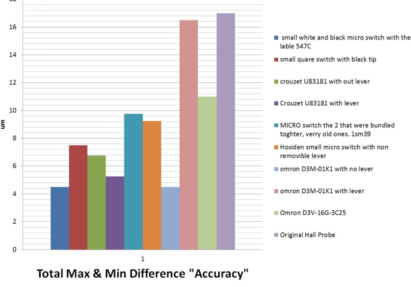
-
@arhi The graphics are interesting, but I have a problem with these statistics because I can not find most of the endstops to buy (only Omron D3M).
And optical endstops: the datasheet don't have any concrete statements, only some curves like +-0.5 mm accuracy (e.g. the ubiquitous TCST2103 based ones). Measuring depends on measured current, so combining it with a good analog-digital currency measurer (like ADS1115) and voltage reference (like LM4040) should improve achievable precision. ADS1115 transmits data with I2C, it should be possible to connect to Duet and decide by threshold.
-
@JoergS5 said in For anyone still using endstop switches...:
@arhi The graphics are interesting, but I have a problem with these statistics because I can not find most of the endstops to buy (only Omron D3M).
That is just some "available data", and there's more if you look for it. Now, I personally would never trust this data for exactly the same reason. I would get the microswitches I can easily source locally, or from some reputable source that can provide the same parts in the future (digikey, farnell, mouser...) and do the test myself.
BTW, you are aware that you can increase the precision of the microswitch by 2 orders of magnitude easy by using a longer lever? Similar with opto too.
And optical endstops: the datasheet don't have any concrete statements, only some curves like +-0.5 mm accuracy (e.g. the ubiquitous TCST2103 based ones). Measuring depends on measured current, so combining it with a good analog-digital currency measurer (like ADS1115) and voltage reference (like LM4040) should improve achievable precision. ADS1115 transmits data with I2C, it should be possible to connect to Duet and decide by threshold.
TBH, if you enclose the opto in a "dark box" and do the proper "slide in fast, retract slow" homing procedure, a simple comparator will do the trick and it will be super repeatable if you don't have huge temp swing and if your Vcc is relatively stable. It will be IMO (have not tested) more precise then measuring analog output and hitting th 'cause in this case you will have both the Vcc regulator and the comparator on the same board at the same temperature so any temp swing will affect them all together :).
Now, as I said, nitpicking with them is IMO huge waste of time. I used optical ones 'cause I was afraid microswitches will fail due to moving parts. But microswitches last decades in lot heavier applications than ours so that was a wrong assumption by me. I was planing for my next machine to use piezo's for positioning but I gave up and a simple printed lever and el-cheapo microswitch can get you where none of the expensive endstops will get you. Just a super simple math, the longer the arm the more precise the movement. It is not very compact for the touch probe, but for XYZ limit switches it's plenty small
-
@arhi Thanks for your additional information. I agree that one has to test himself. Even a tested endstop could be changed in production and has other properties now. The precision data in the datasheet are very fuzzy in addition.
The reason why I prefer optical endstop is that I need endstops which can be "traveled through", from the other side also (a round wheel for 360 degree turns). As far as I see, only magnet based and optical endstops can achieve this. Mechanical ones could be tilted away after measuring, but this will change the reference due to imperfect hinges, and needs an additonal actuator. My needed endstops not only need repeated precision, but also absolute precision to measure the degrees of the wheel (=> optical encoder being better for this requirement, I know...).
The Omron D3M endstops without lever have an overtravel of only 0.4 mm, which limits the speed the endstop can be approached. This may be another aspect to take into account when comparing endstop types. Optical endstops will have a longer overtravel.
-
@JoergS5 said in For anyone still using endstop switches...:
The precision data in the datasheet are very fuzzy in addition.
They are not manufactured to be precise, that's why that data is "fuzzy". The important data is "bouncing", number of open/close cicles during lifetime etc. On some the "pressure force required".. but "precision" is normally not something switch manufacturers care about

The reason why I prefer optical endstop is that I need endstops which can be "traveled through", from the other side also (a round wheel for 360 degree turns). As far as I see, only magnet based and optical endstops can achieve this.
Not sure I follow, all cnc machines use mechanical microswitches that can be "traveled trough" ?!
Something like these (10A 250V IP65):
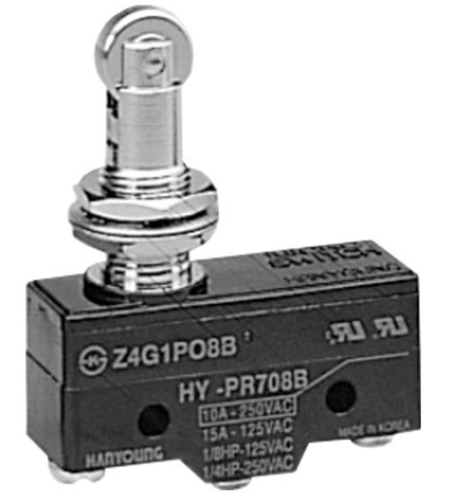
But even when you look at professional endstops, they are IP65, they can survive vibrations, many switches, high forces etc etc, but no "precision" is set there as you don't use switches to home, you use camera or special touch probe.
The Omron D3M endstops without lever have an overtravel of only 0.4 mm, which limits the speed the endstop can be approached. This may be another aspect to take into account when comparing endstop types. Optical endstops will have a longer overtravel.
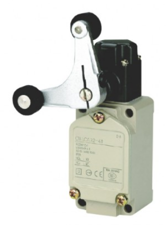
Well what I'm suggesting is something like the second image I put here. The length of the arm defines precision. Shorter the arm side towards bed, better the precision. The sensor on the long end can be whatever, micro switch, hall, optical, inductive..
-
@arhi Thank you for your images, the second one was new for me.
-
@JoergS5 The $3 endstops I used in my printer have LM393 comparators on-board to switch the output hard on/hard off. They can have infinite travel through if you mount them in the right orientation and move the output connector pins to the other side of the PCB.
-
@mrehorstdmd Thank you, I already tried them with success. From the description of the datasheet I am unsure about precision however (I need absolute precision). I will have to test myself, I suspect. I have to measure degrees of a wheel.
Did you use multiple endstops at one axis, is this possible? e. g. in my case with a wheel installing endstops at 0, 90 and 180 degree and verify in Duet software that the expected value matches the true position. A linear actuator could verify begin, middle, end positions (e.g. discover lost steps).
-
@JoergS5 I only used one endstop per axis. I'm not sure how you'd get the Duet to recognize more than one per.
-
@JoergS5 said in For anyone still using endstop switches...:
@arhi Thank you for your images, the second one was new for me.
That's WL-CA32-41 "LIMIT SWITCH FORK ROLLER LEVER" from OMRON (or WLCA32-41 depending on who's selling them).
It is rather standard equipment on CNC machines.
check out:
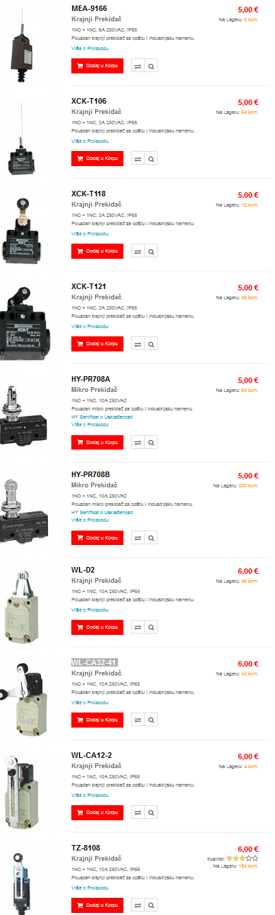
It's rather wrong language I know but you can see the pictures, that's assortment of limit switches commonly used for cnc machines.
CNC limit switches usually have a lever and a lever is longer on the wrong side of precision, meaning they are normally extending the lever so that you need less force to trigger as normally you could not care less for few mm +- on your limit switch on a CNC as it is not used for homing. What I'm suggesting is turning it around and using a short side of the lever for probing and long side of the lever for triggering amplifying the movement increasing the precision (like you have on those super precise indicators for e.g.)
-
@arhi I'll try the -41 one, thanks. - edit: Ouch, cheapest one 35 EUR, most 50 EUR+. I'll wait buying one.
-
@JoergS5 said in For anyone still using endstop switches...:
Ouch, cheapest one 35 EUR, most 50 EUR+. I'll wait buying one.
yes, omron original is ~ $50, but as you can see from the local store snapshot there are PRC clones that are retail here 5-6eur so they are top 4-5$ on PRC sites with shipping
-
no fork types but lot of others
https://www.aliexpress.com/item/32973708437.html -
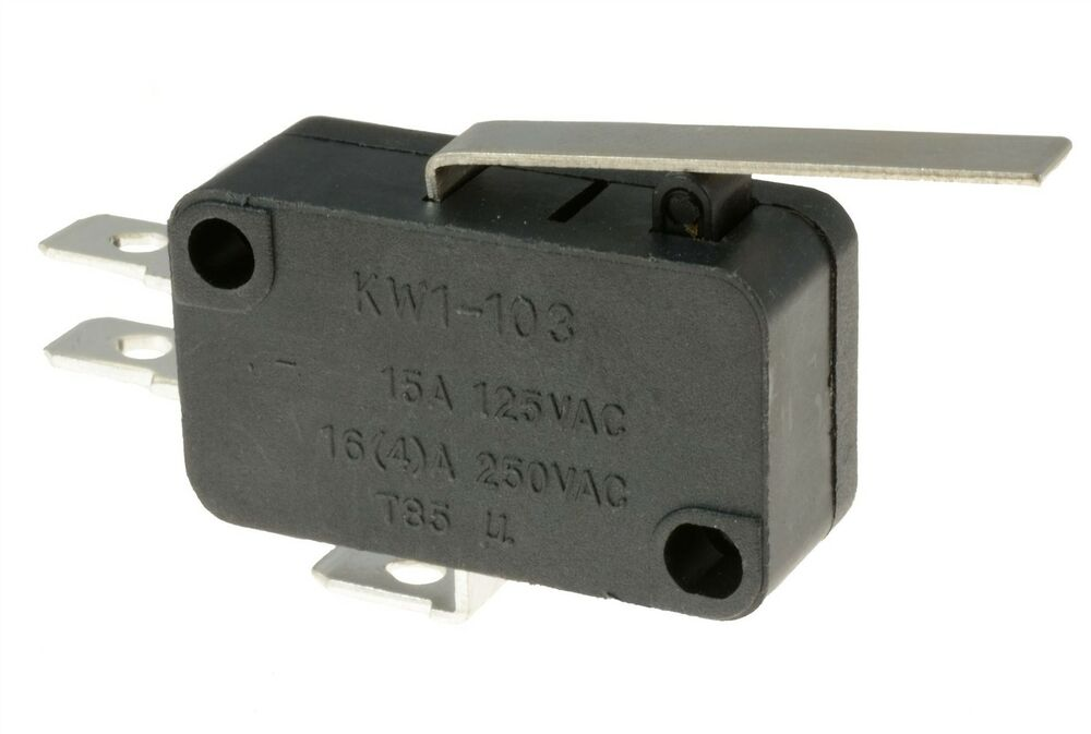
My previous printer had a microswitch for Z homing, similar to the picture below. To improve it's repeatability I remove the metal lever and had the carriage hitting it directly on the plastic actuator. My assumption was that the leverage ratio increases the repeatability error. I never done measurements to confirm it though.
-
i think weather or not the lever improves the repeatability comes down to the rigidity of the whole lever and pivot point.
-
@bearer, let's say that the lever is perfect and the core switch has repeatability error X, doesn't that error multiplied by leverage ratio of the lever?
-
@zapta hm, maybe I read the chart up there wrong, but seemed omrom with lever was less accurate and crouzet was more accurate - as such I assumed it had more to do with the quality of the lever than the lever itself. (could be wrong ofc)
-
-
lever must be stiff, normally on these switches lever is springy intentionally as accuracy is not really important
-
you want to probe with SHORT end of the lever, normally these switches probe with long end of the lever, again, accuracy is not important for normal use and long lever reduce force required to press the spring
so what you need to do is reverse it, use stiff lever and use a lever that's short on the probe side and long on the trigger side, this way you increase force required to press the lever (not a problem on our gear) and increase precision
-