Oddly shaped holes?
-
@Surgikill said in Oddly shaped holes?:
@arhi That's what I was thinking but I have no idea where it's coming from.
Some real knowledge about corexy required here. I have none so can't say really. The regular things to check, what I'd check first is how tight are the pulleys on the motors. But I'm sure someone mentioned that in the long thread and that you already changed that as it's really kind of bacis first thing to check. On the other hand, pulleys with loose set screw moving on the flat of the shaft would totally explain this.
I also can't slice anything right now to test it because prusaslicer won't work.
What's wrong with prusa slicer? Starts up and freezes on the start? You have multiple monitors? There is a bug in the nvidia driver for multiple monitors if you try to start some GL features on the non-primary promonitor it will fail. Solution for prusa slicer is open
%APPDATA%\PrusaSlicer\PrusaSlicer.ini(in my case that is
C:\Users\arhimed\AppData\Roaming\PrusaSlicer\PrusaSlicer.ini)and delete the line
window_mainframe = -8; -8; 2576; 1416; 1(it will have of course other numbers therethen start the prusaslicer, it will work ok.
If you move it from your primary screen to another one, next time it will try to start from where you left it off and will not work again (so delete window_mainframe line again for it to start on main screen)
-
@arhi said in Oddly shaped holes?:
@Surgikill said in Oddly shaped holes?:
@arhi That's what I was thinking but I have no idea where it's coming from.
Some real knowledge about corexy required here. I have none so can't say really. The regular things to check, what I'd check first is how tight are the pulleys on the motors. But I'm sure someone mentioned that in the long thread and that you already changed that as it's really kind of bacis first thing to check. On the other hand, pulleys with loose set screw moving on the flat of the shaft would totally explain this.
I also can't slice anything right now to test it because prusaslicer won't work.
What's wrong with prusa slicer? Starts up and freezes on the start? You have multiple monitors? There is a bug in the nvidia driver for multiple monitors if you try to start some GL features on the non-primary promonitor it will fail. Solution for prusa slicer is open
%APPDATA%\PrusaSlicer\PrusaSlicer.ini(in my case that is
C:\Users\arhimed\AppData\Roaming\PrusaSlicer\PrusaSlicer.ini)and delete the line
window_mainframe = -8; -8; 2576; 1416; 1(it will have of course other numbers therethen start the prusaslicer, it will work ok.
If you move it from your primary screen to another one, next time it will try to start from where you left it off and will not work again (so delete window_mainframe line again for it to start on main screen)
AH HA. Thank you for that. Yea it's off the primary monitor. This is dumb. They need to fix that. I like to keep my CAD on the main monitor and have PrusaSlicer on the secondary.
I can re-check the pulley on the motors, but all the set screws seem tight as balls. I'm thinking it might just be one motor causing the issue, because of the box I printed on the diagonal being more out of dimensions than the box aligned with the axes. (If you turn only one motor on a corexy, it will move the head along a 45 degree diagonal)
-
I just loosened all the belts, re-squared the entire gantry, re-tensioned all the belts and it's still having problems. I've re-designed the Y to X gantry adapters so I can lock the carbon rods into them and see if that fixes it.
-
@Surgikill said in Oddly shaped holes?:
AH HA. Thank you for that. Yea it's off the primary monitor. This is dumb. They need to fix that. I like to keep my CAD on the main monitor and have PrusaSlicer on the secondary.
You of course have NVidia card and Windows 10
 the only combo that have this issue. You will have the same bug with Simplify3D, Netfabb, Craftware, IdeaMaker ... it's a bug in nvidia driver GL
short bug description
If I have openGL application that want to start on screen that is not primary the application will fail to start (it will get stuck running SwapBuffers() for the first time). If you start the application on the primary screen it will start ok, you can now move it to the other screens and it will run normally, the only issue is initializing the GL canvas inside the application, after it is initialized it will run ok.
The issue is with any app trying to initialize GLCanvas on non primary screen. It's there for more than a year and NVidia don't give a #$%^_& about it

I can re-check the pulley on the motors, but all the set screws seem tight as balls.
No clue. Maybe one motor is losing steps, maybe one motor is broken, dunno really, never used corexy so really even my guess here is not very useful. I just chimed in 'cause that image looks like what you can see with heavy backlash on CNC and 'cause the nvidia bug. I'm following up as I'm interested in what's the culprit but can't help.
-
@arhi Yea, I just bought some steel rods and linear bearings to put on the X carriage. If that doesn't fix it, IDK what will.
-
Okay @arhi @mrehorstdmd I got new 12mm steel rods in, and regular LM12UU bearings (not bushings). The quality is definitely better. Here are some pics of a small part and a large part. Not sure what the issue still is, but quality has definitely improved. I'm going to try loosening the belts a tad, they might be too tight.


-
@Surgikill At least your cut is healing. LOL
-
@Coffee said in Oddly shaped holes?:
@Surgikill At least your cut is healing. LOL
I don't even notice them anymore.
-
One suggestion: Remove extruder and mount technical pen and instead of printing write on paper until you solve the circle issue.
Ideally instead of pen using a ballbar would be awesome but who has ballbard these days ( https://resources.renishaw.com/en/download/white-paper-ballbar-testing-with-circle-diamond-square-machining-tests--99016 )
look at this: https://sphereinabox.wordpress.com/2014/07/19/delta-actuator-math-notes/
see the first picture, looks like your problem
write your own g-code and test it with a technical pen, no need to waste plastic and introduce another axis into mix
")
also check out
https://www.thingiverse.com/thing:3060573finally, marlin have support for some backlash testing procedure
M425 - Backlash compensation
I never used it, maybe RRF have something similar, maybe just reading about what they do help you do it manually yourself.. -
@Surgikill I hear ya. Tinkering can lead to your hands/fingers lookin' like ya washed 'em with barbed wire.
-
@Coffee said in Oddly shaped holes?:
Tinkering can lead to your hands/fingers lookin' like ya washed 'em with barbed wire.
100 days tinkering == 1 hour playing with a young cat
-
@arhi said in Oddly shaped holes?:
One suggestion: Remove extruder and mount technical pen and instead of printing write on paper until you solve the circle issue.
Ideally instead of pen using a ballbar would be awesome but who has ballbard these days ( https://resources.renishaw.com/en/download/white-paper-ballbar-testing-with-circle-diamond-square-machining-tests--99016 )
look at this: https://sphereinabox.wordpress.com/2014/07/19/delta-actuator-math-notes/
see the first picture, looks like your problem
write your own g-code and test it with a technical pen, no need to waste plastic and introduce another axis into mix
also check out
https://www.thingiverse.com/thing:3060573finally, marlin have support for some backlash testing procedure
M425 - Backlash compensation
I never used it, maybe RRF have something similar, maybe just reading about what they do help you do it manually yourself..So, according to that picture, I have backlash in my Y axis, which I thought. I'm pretty sure it's "sticktion", just from watching it and moving the gantry by hand. My options are to either get rid of the igus bushings, or try to re-square the gantry because for some reason it's not square. I'm going to order some LM16UU just in case. Probably the last time I use igus stuff. It's been a nightmare. I just wanted to make the printer quieter.
-
I had very nice experience with igus, I used their aluminium rods and their bushings that I pressed in printed blocks... used that on some i3 style printer and apart from being quiet all the ringing was gone
-
@arhi I pressed them into these blocks. Maybe they're too tight? I'm really not sure.
-
@Surgikill when they are too tight they slide harder so your motor needs to work harder and can skip steps for a while, then they "ware out" and slide perfectly, no way they can introduce slop if they are too tight in my opinion. Only issue is if they are too loose.
-
@arhi Here's the latest test piece. It definitely looks butter, but it's still sticking. Not sure how long these bushings need to "wear in" but I've probably put over 20-25 hours on them so far, so they should be pretty worn in.
I have to do a bunch of BS to remove the extruder. I might be able to tape a pen to the side and then try and manually home it.
I ordered some regular LM16UU bearings. I'd really like to get this figured out with the bushings if possible though. They are definitely quieter and provide smoother operation.


-
@Surgikill said in Oddly shaped holes?:
@arhi Here's the latest test piece. It definitely looks butter, but it's still sticking. Not sure how long these bushings need to "wear in" but I've probably put over 20-25 hours on them so far, so they should be pretty worn in.
As long as they are not slopy they are IMO not part of this problem.
I have to do a bunch of BS to remove the extruder. I might be able to tape a pen to the side and then try and manually home it.
tape a pen
hotglue a pen... something like that .. or do a single layer print with extruder but pen is much faster, no need to wait for anything to heat up I ordered some regular LM16UU bearings. I'd really like to get this figured out with the bushings if possible though. They are definitely quieter and provide smoother operation.
If the bushings are not showing slop it's not up to them I'm sure
as I said, start writing some manual gcode to see where the problem is ..
you say if you move in diagonal only one motor motor moves .. so test something like
; add here your temperature stuff for bed and extruder, your normal start code

; do the test
M83               ; RELATIVE extruder move
G0X0Y20Z0.25      ; go to start position, 0.25mm layer
G0X10Y10
G1X50Y50F600E2.352
G1X80Y10F600E2.352
G1X100Y30F600E1.176
G1X70Y70F600E2.352
G1X50Y50F600E1.176
G0Z20
; turn off your bed and extruder heaters now
all moves should be single motor only, and last move should hit exactly the 50,50 coordinate that first move ends at but from different
-
@arhi said in Oddly shaped holes?:
@Surgikill said in Oddly shaped holes?:
@arhi Here's the latest test piece. It definitely looks butter, but it's still sticking. Not sure how long these bushings need to "wear in" but I've probably put over 20-25 hours on them so far, so they should be pretty worn in.
As long as they are not slopy they are IMO not part of this problem.
I don't think it's slop that's the issue. I think they are sticking. It seems to happen more towards the extreme y axis.
as I said, start writing some manual gcode to see where the problem is ..
you say if you move in diagonal only one motor motor moves .. so test something like
; add here your temperature stuff for bed and extruder, your normal start code

; do the test
M83               ; RELATIVE extruder move
G0X0Y20Z0.25      ; go to start position, 0.25mm layer
G0X10Y10
G1X50Y50F600E2.352
G1X80Y10F600E2.352
G1X100Y30F600E1.176
G1X70Y70F600E2.352
G1X50Y50F600E1.176
G0Z20
; turn off your bed and extruder heaters now
all moves should be single motor only, and last move should hit exactly the 50,50 coordinate that first move ends at but from different
I'm pretty bad with gcode. What is that drawing exactly? A box? I'll make it up and see what happens.
-
@Surgikill said in Oddly shaped holes?:
I don't think it's slop that's the issue. I think they are sticking. It seems to happen more towards the extreme y axis.
If they are binding then you have skipped steps, but possible they are binding in a way that for microstepping you are inprecise.
There is a super simple test for that, turn off interpolation as set microstepping to 2 (half step only), and reduce your step/mm for XY 8 times (if you are at 1/16 now) .. the movement will be jerky and circle will be "stepped" and not smooth but should be circle, not that thing you have now.
I'm pretty bad with gcode. What is that drawing exactly? A box? I'll make it up and see what happens.
if you plan on doing a lot of 3d printing, learn it
it's rather simple
it moves your head "to some coordinate" soif you follow the gcode
go to 0,20 then to 10,10, then to 50,50, then to 80,10 -> 100,30 ->70,70 -> 50,50 and finally go to Z20 (raise head or drop table whatever moves in your case)
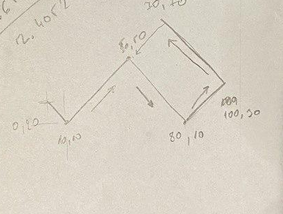
so if you look at 50,50 point, extruder will in first arrive there from 10,10 but coming from "above" from 0,20, then it will change direction coming from 100,30 to 70,70 so when it returns to 50,50 it will be misaligned for the backlash in one of two motors.
You can't make this as "object" as you don't have control in slicer of the direction of the travel, these type of g-codes you have to write yourself to test stuff you want to test... you should then make a mirror of this move to test the other motor (assuming I guessed right the single motor movement on coreXY as I said, zero experience in that department)
BTW if you lock your motors, any direction you can move your head for a fraction of mm ?
-
@arhi said in Oddly shaped holes?:
@Surgikill said in Oddly shaped holes?:
I don't think it's slop that's the issue. I think they are sticking. It seems to happen more towards the extreme y axis.
If they are binding then you have skipped steps, but possible they are binding in a way that for microstepping you are inprecise.
There is a super simple test for that, turn off interpolation as set microstepping to 2 (half step only), and reduce your step/mm for XY 8 times (if you are at 1/16 now) .. the movement will be jerky and circle will be "stepped" and not smooth but should be circle, not that thing you have now.
I'm pretty bad with gcode. What is that drawing exactly? A box? I'll make it up and see what happens.
if you plan on doing a lot of 3d printing, learn it
it's rather simple
it moves your head "to some coordinate" soif you follow the gcode
go to 0,20 then to 10,10, then to 50,50, then to 80,10 -> 100,30 ->70,70 -> 50,50 and finally go to Z20 (raise head or drop table whatever moves in your case)
so if you look at 50,50 point, extruder will in first arrive there from 10,10 but coming from "above" from 0,20, then it will change direction coming from 100,30 to 70,70 so when it returns to 50,50 it will be misaligned for the backlash in one of two motors.
You can't make this as "object" as you don't have control in slicer of the direction of the travel, these type of g-codes you have to write yourself to test stuff you want to test... you should then make a mirror of this move to test the other motor (assuming I guessed right the single motor movement on coreXY as I said, zero experience in that department)
BTW if you lock your motors, any direction you can move your head for a fraction of mm ?
Yea I just wrote that gcode out and it did nada. It didn't even extrude any filament. I'm going to mess with it and see what I can do.
EDIT: Yea I have no idea what it's trying to do, but it's air printing and not extruding anything. I'm just going to try and make a thin wall part and try it.